
Related Manuals for Rekluse CoreEXP 3.0


Summary of Contents for Rekluse CoreEXP 3.0
- Page 1 INSTALLATION GUIDE For Harley-Davidson Cable Actuated Sportster Doc ID: 191-6206A Revision: 062818 ©2015 Rekluse Motor Sports Rekluse Motor Sports, Inc. customerservice@rekluse.com...
-
Page 2: Table Of Contents
Table of Contents OVERVIEW ................... 3 INSTALLATION TIPS ..............3 TOOLS ................... 4 INCLUDED PARTS ............... 5 BEFORE YOU BEGIN ..............6 DISASSEMBLE CLUTCH .............. 6 ASSEMBLE THE CLUTCH BASKET .......... 15 INSTALL THE CLUTCH PACK ........... 17 INSTALL THE PRESSURE PLATE..........21 SET INSTALLED GAP .............. -
Page 3: Overview
Work in a well ventilated area. • Use the torque values listed in the instructions. Otherwise, use the torque specifications found in your OE service manual. • Visit www.rekluse.com/support for a full parts fiche illustration and part numbers. Pg. 3... -
Page 4: Tools
TOOLS • ¼” hex key • 1 1/8” socket • 5/16” hex key • 1 3/16” socket • 3/16” hex key • Torque wrench • 5 mm hex key • Telescoping magnet • 5/32” hex key • Dental pick • 5/8” open-end wrench •... -
Page 5: Included Parts
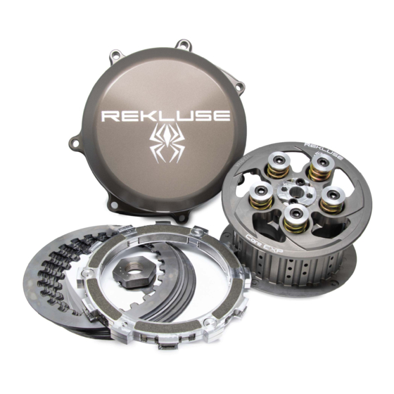
INCLUDED PARTS Item Description Qty. EXP bases Wedge assembly Quarter-turn pins (extra included) 60.1 EXP adjustment springs – colors vary Retaining ring Center clutch Steel drive plates - .040” (1 mm) Lining plate Pressure plate with bearing Core EXP clutch spring kit 60.2 Pressure plate springs Screw sleeves... -
Page 6: Before You Begin
BEFORE YOU BEGIN • Rekluse recommends replacing the chaincase cover gasket when installing this product. • The OE basket bearing may need to be replaced if it shows signs of excessive wear. DISASSEMBLE CLUTCH 1. Fully collapse the in-line cable adjuster, so that the clutch lever becomes very loose at the perch. - Page 7 4. On the primary chain case, use a 5/8” wrench to remove the oil drain plug, then drain the oil into a suitable container. 5. Loosen the chain tensioner lock nut, then turn the chain tensioner adjustment bolt counterclockwise until it spins freely.
- Page 8 8. Remove the derby cover and the O-ring gasket. 9. Remove the spring and the jam nut from the actuating mechanism. Set these aside. 10. Use a flat blade screwdriver to turn the threaded stud clockwise to remove the nut. Set it aside. 11.
- Page 9 12. Hand thread the clutch spring compressor tool onto the throw-out rod. 13. Use a 9/16” open-ended wrench to hold the clutch tool shaft in place. Slowly turn the compressor tool handle clockwise until the spring is compressed enough to remove the snap ring.
- Page 10 14. Use a pair of pliers to remove and discard the clutch spring retaining ring. 15. Remove the OE clutch Belleville spring and pressure plate and set them on a workbench. 16. Use a 9/16” open-ended wrench to hold the clutch tool shaft in place.
- Page 11 17. Unthread the clutch tool from the throw-out rod and remove it, then separate the Belleville spring from the pressure plate. 18. Use snap ring pliers to remove the snap ring from the throw- out assembly, then remove the throw-out assembly from the pressure plate.
- Page 12 20. Using an impact gun and socket, remove the right hand thread crankshaft nut by turning it counterclockwise. Set it aside. 21. Remove the left hand thread center clutch nut by turning it clockwise to remove it. Set it aside. 22.
- Page 13 23. Remove the drive gear, clutch assembly, and chain simultaneously. All three parts must be removed as one unit. • Do this by grasping the drive gear and clutch assembly in separate hands, then firmly slide them off their respective shafts.
- Page 14 25. Remove the clutch pack from the clutch basket, then separate the OE friction disks from the OE drive plates. There will be 8 friction disks and 7 drive plates. 26. Flip the basket assembly over on a workbench, then use snap ring pliers to remove the center hub retaining ring.
-
Page 15: Assemble The Clutch Basket
ASSEMBLE THE CLUTCH BASKET 1. Use a shop/bench press to press out the OE center hub from the clutch basket. Note: Check the OE basket bearings for any signs of excessive wear or float. If the bearing appears worn, replace it with a new OE unit available at your local dealership. - Page 16 OE basket. Use the press if needed to press the hub into the basket. Let the basket cool. Note: This thermal fit may allow for the Rekluse center hub to slide into the basket bearing without the need of a press.
-
Page 17: Install The Clutch Pack
4. After the basket has cooled, flip the basket over and install the included Rekluse 35 mm retaining ring into the groove on the Rekluse center hub. INSTALL THE CLUTCH PACK 1. Install a Rekluse steel drive plate 1 into the clutch basket, then install an OE friction disk. - Page 18 3. Install the EXP disk on top of the last steel drive plate. Note: • If you bike’s idle RPM has changed from stock – meaning that it idles either higher or lower than the stock setting – see the EXP Tuning Options section to determine the best EXP spring setting before installing the EXP disk.
- Page 19 5. Install the drive gear, clutch assembly, and chain at the same time. Do this by grasping the drive gear and clutch assembly and firmly slide them onto their respective shafts. 6. Place a primary wedge tool between the teeth of the drive gear and the clutch assembly gear.
- Page 20 8. Reinstall the OE Belleville washer with the cup-side facing up on top of the OE center clutch nut. 9. While keeping the OE Belleville washer on the nut, reinstall the center clutch nut onto the clutch shaft by turning it counterclockwise.
-
Page 21: Install The Pressure Plate
INSTALL THE PRESSURE PLATE 1. Index the lining plate onto the backside of the Rekluse pressure plate, aligning the plate teeth with the machined notches in the pressure plate. 2. Install the OE throw-out through the backside of the Rekluse pressure plate. - Page 22 3. Install the pressure plate assembly onto the clutch assembly. 4. Install the Rekluse pressure plate springs, then install the screw sleeves. Install the pressure plate screws into the screw sleeves. 5. Torque the pressure plate bolts to 9 ft-lb (12 N-m).
- Page 23 7. Check the inside of the primary case cover to make sure the clutch actuating mechanism is indexed properly into the key slot on the back side of the case. 8. Reinstall the OE primary case cover. Note: The easiest way to perform this step is by first aligning the shifter shaft with the primary case and sliding it on part-way.
-
Page 24: Set Installed Gap
SET INSTALLED GAP The “Installed Gap” is the space in the clutch pack created by the adjustment at the throw-out rod. This gap is what allows the clutch to spin freely until the desired RPM is reached for engagement. 1. Reinstall the OE threaded nut onto the OE threaded throw- out rod. -
Page 25: Finish Installation
FINISH INSTALLATION 1. Reinstall the OE clutch actuating mechanism spring by pressing it onto the lock nut in the clutch actuating mechanism. 2. Reinstall the gasket for the OE derby cover, then install the derby cover. Lightly applying grease to the o-ring can help hold it in place when installing the derby cover. - Page 26 4. Remove and set aside the OE chain inspection cover and gasket. Gasket Inspection cover 5. Verify that the lock nut on the chain tensioner is still loose. Then, turn the adjustment bolt on the chain tensioner clockwise until the drive chain has 3/8” to 1/2 of travel in it. 6.
- Page 27 7. Install the oil drain-plug. Torque to 14 ft-lb (19 N-m). 8. Insert a funnel into the inspection window and pour 1 quart of OE recommend oil into the primary chaincase. 9. Reinstall the OE chain inspection cover gasket and inspection cover.
-
Page 28: Reset The Lever Free Play
RESET THE LEVER FREE PLAY “Lever free play” is essentially the “slack” in the clutch cable before it starts actuating the clutch. Applying a light finger pressure will take up this slack. 1. Expand the in-line adjuster until the cable slack is between 1/16”... -
Page 29: Check Free Play Gain
CHECK FREE PLAY GAIN It is very important that you understand how to verify the correct installed gap by checking Free Play Gain. The installed gap is what allows the auto function of the product to perform properly. Correct Free Play Gain = Correct installed gap Setup, break-in, and rechecking the installed gap is CRUCIAL. -
Page 30: Two Ways To Check For Free Play Gain
Two Ways to Check for Free Play Gain The following steps explain 2 ways to check Free Play Gain. One way uses the rubber band Rekluse includes in the clutch kit, and one uses your hand. You can use either method to check for Free Play Gain. -
Page 31: The Rubber Band Method
Rekluse recommends that you begin with the rubber band method first to check for Free Play Gain and then learn the hand method. The rubber band will help you learn how to recognize Free Play Gain until you are comfortable with the hand method. - Page 32 b) Stretch the included rubber band between your thumbs, then place the top end of the rubber band on the outer end of the left handlebar grip. c) While holding the top end of the rubber band against the handlebar, stretch the band downward, then loop it through itself.
-
Page 33: The Hand Method
When the bike returns to idle, rest your hand across the clutch lever. Rev the engine again to 3,000-5,000 RPM so you can observe the movement while feeling for Free Play Gain with your hand. The Hand Method Use the hand method to check Free Play Gain before the start of every ride for optimum performance and longevity of your new clutch. -
Page 34: Adjust The Installed Gap
ADJUST THE INSTALLED GAP After checking for Free Play Gain, you may need to adjust the installed gap. If Free Play Gain is optimal, continue to “BREAK IN THE NEW CLUTCH.” If Free Play Gain is not optimal, the installed gap needs to be adjusted. The installed gap should be fine-tuned in small increments and then recheck Free Play Gain. -
Page 35: Break In The New Clutch
BREAK IN THE NEW CLUTCH Once you install your new clutch, it is important to break it in. A series of roll-on starts are used to break in the clutch. Follow these procedures for breaking in your clutch and any time new friction disks, EXP bases, Teflon pads, or wedges are installed. - Page 36 Note: If the engine wants to stall or the creep is excessive, the idle may be too high or the installed gap may be too small. Make necessary adjustments before proceeding. 5. Place the bike in NEUTRAL and recheck Free Play Gain. Continue to adjust the installed gap until the clutch lever is 1/8”-1/4”...
-
Page 37: Exp Tuning Options
You can tune the engagement RPM of the EXP disk by changing the spring configuration. The EXP disk comes set with the recommended “Medium” setting from Rekluse, based on an idle of RPM = 1050. If your idle is higher than 1050 RPM, it may be best to install the “High”... - Page 38 2. With the pin still pushed past the locking collar, turn 90° to remove the pin and spring. Push past locking tab locking collar 3. Remove the remaining 2 pins and springs from the same side of the EXP base. 4.
- Page 39 7. If you need to disassemble the EXP disk, you can watch the video on our website under Tech Tips at www.rekluse.com/support/videos. Note: To maintain even pressure, when using two different color spring sets, install one set of 3 on one side of the EXP and the remaining set of 3 on the other side.
-
Page 40: Lever Safety Straps
Technical Support hours: Monday thru Friday: 8:00 a.m. - 5:00 p.m. Mountain Time zone Phone: (208) 426-0659 Email: tech@rekluse.com • Additional contact information can be found in the User’s Guide. Doc ID: 191-6206A Pg. 40 Doc Rev: 062818...
Need help?
Do you have a question about the CoreEXP 3.0 and is the answer not in the manual?
Questions and answers