
Related Manuals for Data I/O PSV5000


Summary of Contents for Data I/O PSV5000
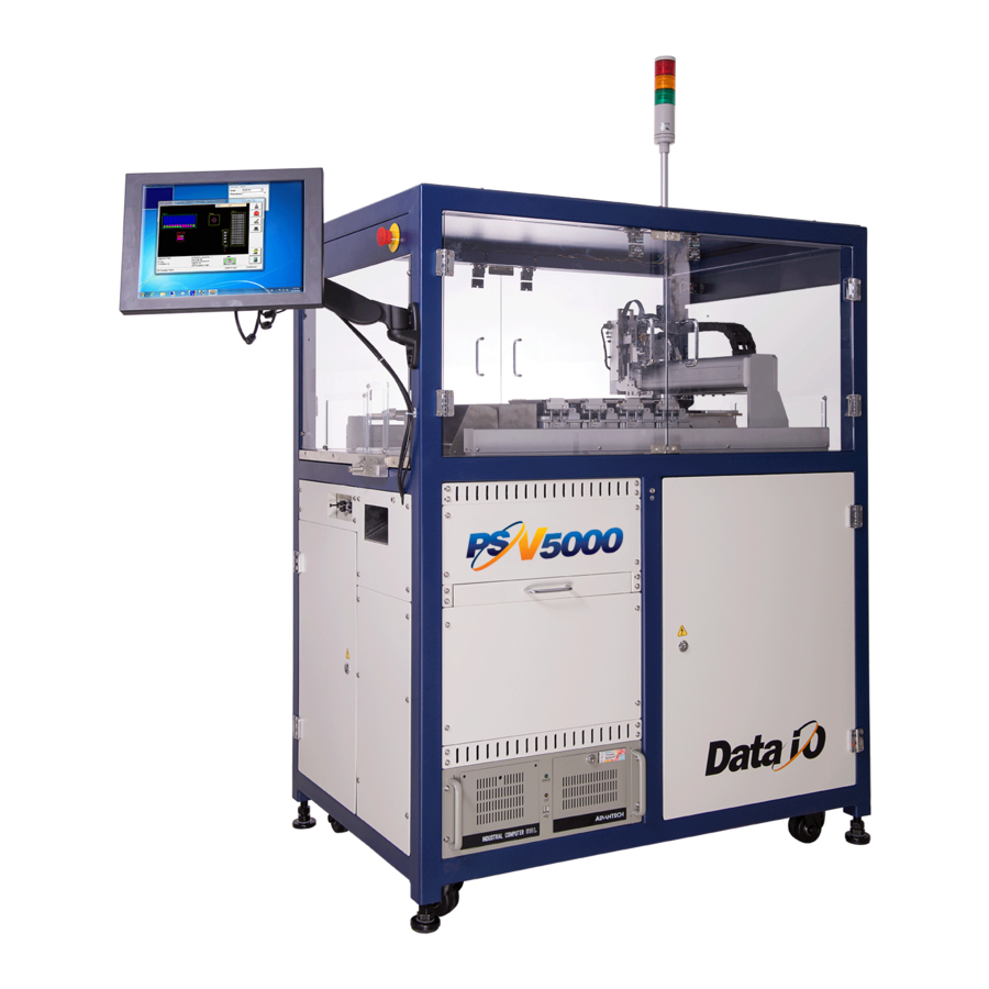
- Page 1 Operator’s Manual Automated Programming and Handling Now available with LumenX Programmers 096-0466-001E...
- Page 2 Any algorithms, adapters or other Data I/O products provided or sold by Data I/O to you must first be tested and verified by you for use in your application prior to use in a production environment. Data I/O does not warrant that the Data I/O products will meet your requirements or that operation of the Data I/O products will be uninterrupted or error-free.
-
Page 3: Table Of Contents
SAFETY MESSAGES AND PRECAUTIONS Warnings and Cautions Safety Systems Emergency Stop (E-Stop) Buttons Safety Doors and Interlocks Electrostatic Discharge RUNNING A JOB ON PSV5000 Requirements List of Steps to Start a Job 1>> Checking the System 2>> Installing Input/Output Media... - Page 4 Power Up the Tray Feeder Verify Tray Feeder Initialization Teaching the Tray 1 Location 7>> Turning PSV5000 System Power ON 8>> Selecting a Job—Starting CH700 To select and start a job for FlashCORE Programmers To select and start a job for LumenX Programmers 9>>...
-
Page 5: Psv5000 Machine Components
■ Work Surface Components ≡ Programmer Overview PSV5000 Machine Components This Visual Index of PSV5000 locates features and subassemblies on the machine. E-Stop Gantry Optional: Tape Output Work surface Monitor and Keyboard ESD ground Optional: connection Laser Control Light Tower... -
Page 6: Work Surface Components
Magnet Figure 2: Some features on the PSV5000 work surface. The system can be configured with a reject tray or a reject bin. Note that the static trays and Tray Feeder would not both be used at the same time. (Refer to Owner’s Manual or on-screen Help). -
Page 7: Power Panel Components
Rear View of PSV5000. For information on connecting the facili- ties, see the Owner’s Manual. Programmer Overview Two programmer models are available for the PSV5000: both models can be in- stalled next to each other, but programming jobs can only be set to use one model. PSV5000 Operator’s Manual... - Page 8 PSV5000 Machine Components ■ Power Panel Components LumenX Lumen™X is Data I/O’s latest programmer at the time of this document. Each LumenX programmer requires one to two Actuator Plates and one to eight Socket Adapters for the specific device package being programmed.
- Page 9 Actuator Plate Socket Adapter Programmer Figure 6: FlashCORE III programmers on PSV5000. LED Interpretation on FlashCORE Programmers Figure 7: Each FlashCORE Socket Adapter has one red LED per socket. A) Standard Adapter; socket 2 has failed. B) HIC Adapter. Socket 3 has failed.
- Page 10 PSV5000 Owner’s Manual is in the C:\CH700 directory on PSV5000 is a programming and handling system for traditional and fine-pitched the Handler computer integrated circuits (devices). It accepts most package types. The on-screen applica- and also available on tion that runs PSV5000 is CH700.
-
Page 11: Safety Messages And Precautions
This is a caution message! CAUTION: It calls your attention to potentially hazardous situations and practices Definition of a that might damage equipment. Caution–> (The potential loss is not as serious as a warning.) PSV5000 Operator’s Manual - 7 -... - Page 12 —Laser Hazard Warning — ADVERTENCIA de peligro del laser — Laser-Hazard Warning —Compressed Air Warning — ADVERTENCIA de aire comprimido — Druckluft-Warnung —Electrostatic Discharge Warning (ESD) — ADVERTENCIA de descarga electrostática — Elektrostatische Entladung Warnung - 8 - Data I/O ■ 096-0466-001E...
-
Page 13: Safety Systems
Two large, red Emergency Stop buttons are located near the top of the PSV5000 System—one on the left side near the front and one on the right side near back of the machine. When an E-Stop button is pressed, the gantry stops moving immediately. -
Page 14: Safety Doors And Interlocks
(ground) exists between a static-sensitive device or component, its environment, and the operator. Operators should wear an antistatic wrist strap (Data I/O part number 440-0021-001+) connected to one of the grounding connections on the machine. The wrist strap should contain a 1–10 M-ohm current limiting resistor. - Page 15 Vacuum tools use a squeezable air bladder for suction. There are a variety of mod- els, sizes and tips. Some tips are replaceable. Figure 3: A Vacuum Tweezer: Data I/O PN 565-8000. PSV5000 Operator’s Manual - 11 -...
- Page 16 • Do not operate the system if the safety shield doors or access doors are not in their normal operating positions (unless you are a Data I/O trained technician and are explicitly directed to do so by instructions in this manual).
-
Page 17: Running A Job On Psv5000
• Make sure all assemblies needed for the target job, such as the Single Tray Feeder, a Marking System or the Tape Output System, are in- stalled on the PSV5000 Machine. Refer to Chapter 2- Set Up of the Owner’s Manual for more information. -
Page 18: 1>> Checking The System
Running a Job on PSV5000 ■ List of Steps to Start a Job 1>> Checking the System Before you set up for your job, check that: • All side panels and doors are closed • No one is working on the machine. -
Page 19: Setting Up Device Trays And Reject Bin
Package File it must be corrected). 1 orientation for tray and tape input. On the PSV5000, Pin 1 on Data I/O sockets is toward the left side of the Socket Adapter (viewed from the front of the machine). Orientation of Trays FOR TRAYS ORIENTED with the long side parallel to the Y-axis, orient the input and output trays with the beveled corner to the near right. - Page 20 Running a Job on PSV5000 ■ List of Steps to Start a Job Bevel Tray for reject, output, or auxiliary Tray for reject, output, or auxiliary Input Tray Securing Magnet (typical) Reject Bin shown here in green Figure 4: Common static tray locations. A reject bin may be used instead of a tray.
- Page 21 When static trays are used, typically there are three tray mounts on the the Park position, workspace—input, output, and reject (near left). A) Refer to Turning PSV5000 System Power If using optional input/output media, you might not need to ON on page 51, and install some, or any, of these trays.
-
Page 22: Installing The Tape-In Module Option
Running a Job on PSV5000 ■ List of Steps to Start a Job Installing the Tape-In Module Option PSV5000 can be configured with an optional Tape-In Module (Tape Feeder) for input media. The Tape Feeder installs on the left of the machine. A safety plate covers the opening in the safety door when a feeder is not installed. - Page 23 If device tape is already loaded on the feeder, ensure it gets started down the chute in the workspace. Pocket Tape Chute on the PSV5000. Figure 8: The Tape-In slot and spring clamp on PSV5000. PSV5000 Operator’s Manual - 19 -...
- Page 24 Running a Job on PSV5000 ■ List of Steps to Start a Job Figure 9: A. Push the mounting block of the Feeder down into the clamp. B. Feeder has snapped into place. 5. Insert the communication cable part way into the socket on the handler...
-
Page 25: Installing The Tape Rewind Module
1. Secure the Take-Up frame to the front panel. 2. Connect the power cable. 3. Install the proper sized take-up reel. Figure 10: The Tape Rewind/Take-Up module on PSV5000. 4. Power On the Tape Rewind and confirm the spindle starts spinning. Figure 11: The Tape Rewind motor controls. - Page 26 Running a Job on PSV5000 ■ List of Steps to Start a Job Operating the Tape Rewind Module The only connection on the Tape Rewind module is for electrical power, so it has no communication interface and does not require any software config- uration in CH700, WinAH400.ini, or otherwise.
-
Page 27: Checking The Tape Output Option
■ List of Steps to Start a Job ≡ Installing Input/Output Media Checking the Tape Output Option Set up of the Tape Output is described in the PSV5000 Owner’s Manual. Figure 12: The Taper/Tape Output module. Routing the Carrier Tape 1. - Page 28 Running a Job on PSV5000 ■ List of Steps to Start a Job 4. Ensure there is an empty take-up reel on the take-up reel spindle. Take-Up Reel Figure 15: Mounting an empty tape take-up reel. Routing the Cover Tape 1.
- Page 29 6. Use adhesive tape to secure the end of the tape to the take-up reel. 7. On the left side of the controller box, use the Up and Down arrows to control the motor tension. Figure 18: Press ‘Up’ and ‘Down’ arrow buttons for motor tension. PSV5000 Operator’s Manual - 25 -...
- Page 30 Running a Job on PSV5000 ■ List of Steps to Start a Job Configuring the Heat Sealer Complete the following steps to configure the heat sealer. For steps on con- figuring the press sealer, see page 28. 1. On the Control Panel, press the Heat button to power-up the sealer.
- Page 31 If the cover tape is intact after completing both tests, then visually in- spect the taped devices for any excess adhesive/glue. If adhesive is vis- ible, then decrease the roller pressure (turn the sealer adjustment screw counter-clockwise) and test again. PSV5000 Operator’s Manual - 27 -...
- Page 32 Running a Job on PSV5000 ■ List of Steps to Start a Job 11. The Taper is ready for operation. On the Status screen, press Run. Figure 24: Press ‘Run’ button to start the taper. Configuring the Press Sealer 1. On the Control Panel, ensure that Power is On but Heat is Off.
- Page 33 Perform a twist test by giving the tape a slight twist, noting if the cover tape detaches from the carrier tape. If either test produces loose cover tape, increase the roller pressure of the press sealer (turn the sealer adjustment screw clockwise). PSV5000 Operator’s Manual - 29 -...
- Page 34 PSV5000 System to monitor quantity. When the PSV5000 job is run, devices are placed at the Tape-Out pick point. Ending a Run of Taped Devices When the batch size has been reached: 1.
-
Page 35: 3>> Socket Adapters And Actuator Plates
■ List of Steps to Start a Job ≡ Socket Adapters and Actuator Plates 3>> Socket Adapters and Actuator Plates Data I/O recommends installing Socket Adapters before a job has been started (be- fore the CH700 Software is started). However, PSV5000 power can be ON. -
Page 36: Installing Adapters And Actuators On Flashcore
Running a Job on PSV5000 ■ List of Steps to Start a Job Electrostatic discharge (ESD) hazard! To prevent CAUTION: damage to Socket Adapters and devices from ESD, always wear an antistatic wrist strap. The wrist strap should be connected to the grounding socket on the front of the machine and should contain a 1 M-ohm to 10 M-ohm current limiting resistor. - Page 37 Figure 32: Removing the Socket Adapter from a programmer. 5. Insert the correct Socket Adapter for your target device, making sure that it seats on the dowel pins, then screw in the two bracket screws. PSV5000 Operator’s Manual - 33 -...
- Page 38 Running a Job on PSV5000 ■ List of Steps to Start a Job To tighten socket adapters/boards, the recommended torque range for FlashCORE programmer screws is 1.4 – 1.5 Nm / 12.4 – 13.3 lbf-in. 6. Install the correct Actuator Plate by placing it into the slot on the programmer bracket and sliding in until it snaps into place.
-
Page 39: Adjusting The Actuator Plates
Install in reverse order (ensure actuator plates all face the same direction). HIC (High Insertion Count) Actuator Plates must be used with HIC Socket Adapters. HIC adapters have a radius on the under- side of the adjustment bars (similar to the HIC for FlashCORE. PSV5000 Operator’s Manual - 35 -... - Page 40 Running a Job on PSV5000 ■ List of Steps to Start a Job Actuator Plates should all be oriented the same: all keyhole slots toward operator, for example. Figure 35: Actuator Plates for LumenX programmers. Shown with plates and without.
- Page 41 4. Test bar placement; with machine air off, manually press the actuator down to contact the socket body. Ensure it opens the socket correctly. Readjust the bar if necessary. Adjust other Actuator Plates similarly as needed. PSV5000 Operator’s Manual - 37 -...
-
Page 42: 4>> Identifying The Correct Probes
Running a Job on PSV5000 ■ List of Steps to Start a Job 4>> Identifying the Correct Probes Different-sized devices may require a different-sized probe tip. For the most-reliable performance, use the largest nozzle/rubber cup outer diameter (O.D.) possible for the target device so as to create optimal vacuum suction and ‘blow-off’... - Page 43 B. The 1.3mm probe tip does not use a nozzle. Figure 38: 1.3 mm probe tip requires no nozzle/cup. C. For all other outer diameters, the nozzle has a mounting square/hole that slides onto the probe tip. Figure 39: Mounting square for nozzles. PSV5000 Operator’s Manual - 39 -...
-
Page 44: Removing And Installing The Probe
Running a Job on PSV5000 ■ List of Steps to Start a Job 2. Now select the appropriate Probe Tip (based on your selection of the optimal nozzle in Step 1). All of the tips have only 1 of 2 different mounting squares: 1.9 or 2.7 mm. - Page 45 Fixed Aligning pin Spring Clip Pull (shown gold here) Probe Tip Pull Figure 42: If a Retaining Clip was used, remove the Spring Clip from the probe prior to pulling off the tip. PSV5000 Operator’s Manual - 41 -...
-
Page 46: Removing The Probe Holder
Running a Job on PSV5000 ■ List of Steps to Start a Job 6. If a Retaining Clip was used, remove it and pull down on the probe tip to pull it off the probe holder. 7. Referring to the PNP Head Probe Tips table on page 38, select the correct probe tip, or tip + nozzle. -
Page 47: How To Teach A New Tool Position
1. Click the Tool command in the Gantry window (white arrow). 2. Click any of the Arrow buttons (circled in pur- ple) to move the head to a desirable new Tool position. 3. Click Save. PSV5000 Operator’s Manual - 43 -... -
Page 48: 5>> Installing The Correct Laser Shuttle Tips
Running a Job on PSV5000 ■ List of Steps to Start a Job 5>> Installing the Correct Laser Shuttle Tips For jobs that use the laser marking option with tray output only, a laser shuttle is used and the vacuum tips must be of adequate size for the vacuum to hold the device. -
Page 49: 6>> Running The Automatic Tray Feeder
■ List of Steps to Start a Job ≡ Running the Automatic Tray Feeder 6>> Running the Automatic Tray Feeder There is an automatic Tray Feeder option available for the PSV5000 System. Chapter 2 of the Owner’s Manual discusses setting it up. This Chapter 6... -
Page 50: Power Up The Tray Feeder
Running a Job on PSV5000 ■ List of Steps to Start a Job Power Up the Tray Feeder 1. Ensure the Tray Feeder 35 utilities are plugged into the PSV5000 Machine and the Tray Feeder power switch is in the ON posi- tion. - Page 51 6. In the I/O Interface dialog box, click the AutoTray tab, then click Cycle. Figure 49: Click ‘AutoTray’ tab to cycle the Tray Feeder. 7. Confirm that the shuttle elevator moves from the Input stack to the Tray 1 location inside the PSV5000. PSV5000 Operator’s Manual - 47 -...
-
Page 52: Teaching The Tray 1 Location
Running a Job on PSV5000 ■ List of Steps to Start a Job Teaching the Tray 1 Location 1. In the CH700 Setup window, click System (in the right pane). 2. In the System window, click Gantry. Figure 50: Click ‘Gantry’ for handler functions. - Page 53 9. Now click the Trays tab, set the Dimensions for Tray 1 (number of devices per column and row), and then click the Diagonal Corner button. Figure 54: Setting the dimensions for your specific tray/device. PSV5000 Operator’s Manual - 49 -...
- Page 54 Running a Job on PSV5000 ■ List of Steps to Start a Job 10. After PnP head moves to opposite corner of the tray, click X,Y AutoFind. Figure 55: Click ‘X,Y AutoFind’ again to teach the opposite corner. 11. If you see another confirmation dialog box about overwriting previous values, click Yes to continue.
-
Page 55: 7>> Turning Psv5000 System Power On
■ List of Steps to Start a Job ≡ Turning PSV5000 System Power ON 7>> Turning PSV5000 System Power ON Before you turn on power, check that: All safety doors are closed The external air line is connected, the air pressure switch is in the ON position, and the pressure indicator number is green. -
Page 56: To Select And Start A Job For Flashcore Programmers
CH700. Figure 57: Select a Task and click Run to run a job on PSV5000. 3. A Footnotes Dialog displays. Take note of the Socket Adapter and Actuator Plate part numbers required. Click OK to close the dialog. - Page 57 (if Display Checksum option is checked in TaskLink). Click Yes. Figure 59: Click ‘Yes’ to launch CH700 Software. Figure 60: The CH700 Main window for the PSV5000 opens with a job loaded and job name displayed (arrow). PSV5000 Operator’s Manual...
-
Page 58: To Select And Start A Job For Lumenx Programmers
Running a Job on PSV5000 ■ List of Steps to Start a Job To select and start a job for LumenX Programmers 1. Double‐click the LumenX Data Management Software icon. 2. Click your job name. If no jobs display, see the on‐screen Help for pointing LumenX to the correct directory. - Page 59 LumenX DMS must be in PSV Mode for it to open CH700 (Settings > Settings, set Presenter Mode to PSV Mode). 6. Click Run. Both TaskLink and LumenX Data Management Software open CH700. Figure 63: The CH700 Main window opens with a job loaded. PSV5000 Operator’s Manual - 55 -...
-
Page 60: 9>> (Optional) Preselecting Programmers
Running a Job on PSV5000 ■ List of Steps to Start a Job 9>> (Optional) Preselecting Programmers The PSV5000 can be configured with up to six FlashCORE programmers, five LumenX programmers, or a combination of the two. For efficiency, shut off programmers that are not used for a particular job: 1. -
Page 61: 10>> Setting Media And Options-The Setup Window
. To confirm that the winah400.ini file is set to Auto Tray, view the Run window. Yellow hatch marks for Tray Feeder indicator. 3. (Optional) For laser marking devices, turn the Laser Marking key-switch to ON (clockwise). Ensure the correct laser shuttle tips are installed. PSV5000 Operator’s Manual - 57 -... - Page 62 Running a Job on PSV5000 ■ List of Steps to Start a Job Figure 65: The SETUP window requires selections for input, output, and reject media on the Options tab. Only options set in the WinAH400.ini file will display. Common setups will not display all the optional features that are shown here.
-
Page 63: Verifying Media Setup
See the online Help for instructions editing the WinAH400.ini file or contact Data I/O Customer Support or a local Data I/O approved service representative. Verifying Media Setup 1. At the Setup window, click the Job Info tab. - Page 64 Running a Job on PSV5000 ■ List of Steps to Start a Job Figure 67: The Keyboard dialog opens after clicking in the Pass Limit field. The <<<< button erases the right-most digit. Exit cancels any changes. Possible socket and device damage! If an incorrect...
-
Page 65: 11>> Starting Programming
The invisible infrared light can cause third-degree burns even when defocused. The output beam also produces visible and invisible radiation harmful to eyes. Personnel around the equipment must always wear safety protective glasses of correct wavelength. PSV5000 Operator’s Manual - 61 -... - Page 66 Running a Job on PSV5000 ■ List of Steps to Start a Job Starting the Laser PC 1. Ensure the power to the laser PC is ON. Blue light is on. To extend the service life of laser, turn it OFF if...
- Page 67 Fume Extractor power ON. To manually start the Laser Fume extractor, 1. Turn the PSV5000 power is OFF. Refer to Turning Power OFF on page 74. 2. Open the front lower access door. 3. Turn the fume extractor power ON.
-
Page 68: Removing Devices
Running a Job on PSV5000 ■ Removing Devices Removing Devices Remove unwanted devices in programmer sockets by: Manually 1. Pause or Finish (end) a job. 2. Right-click on the desired programmer to open a submenu, and then click Opener UP. -
Page 69: Emergency Stop
Figure 70: There are two Emergency Stop (E-Stop) buttons: on left near front, and on right near back of the machine To restart the System —after pressing an E-Stop Figure 71: Popup message: Check the E-Stops. PSV5000 Operator’s Manual - 65 -... -
Page 70: Pausing A Job
Running a Job on PSV5000 ■ Stopping the System 1. Rotate the E-Stop button clockwise until it springs back to its full height. Check the second E-Stop button if necessary. 2. Click Retry to continue. If possible the system will re-establish commu- nication within 30 seconds. -
Page 71: Ending A Job
CH700 SW will continue the job where it left off (when Finish was clicked). Empty the reject bin whenever it looks full; there is no ‘Full’ It is NOT necessary to restart programmers between jobs. indicator. Empty the reject bin or tray after ending a job. PSV5000 Operator’s Manual - 67 -... -
Page 72: Light Tower Interpretation
Light Tower Interpretation ■ Stopping the System Light Tower Interpretation During operation of the PSV5000 System, you can monitor the light tower to reduce system down time. The light tower displays the following conditions: Machine Light Condition Action Required Possible Causes Status ... - Page 73 ■ Stopping the System ≡ Ending a Job Machine Light Condition Action Required Possible Causes Status Green Running No operator action Processing devices, or Processing clearing sockets to out- normally needed. put. PSV5000 Operator’s Manual - 69 -...
-
Page 74: Changing Programmer Status
Changing Programmer Status ■ Disabling Programmers Changing Programmer Status PSV5000 may automatically disable a programmer for various reasons (for example, if there are repeated continuity errors or vacuum issues). The op- erator may also choose to disable a programmer, or otherwise change the status of a programmer. - Page 75 Figure 73: Right-click a programmer in the Run window to change the status of the programmer, toggle the vacuum, or perform various other functions. NOTE that “All => EMPTY” and “=>EMPTY” only change the status and do not empty the socket(s). PSV5000 Operator’s Manual - 71 -...
-
Page 76: My Jobs That Use The Same Setup
Tape Tape Laser Mark • __________________ Tray Tray 3D Inspect VX Tube Tube 3D Inspect UX • __________________ Reject Type • __________________ _____________ - 72 - Data I/O ■ 096-0466-001E... - Page 77 _____________ Tape Tape Laser Mark • __________________ Tray Tray 3D Inspect VX Tube Tube 3D Inspect UX • __________________ Reject Type • __________________ _____________ PSV5000 Operator’s Manual - 73 -...
-
Page 78: Finishing A Job
3. Empty the reject container(s). 4. Remove programmed devices. Turning PSV5000 System Power OFF When the PSV5000 System will not be run overnight, or before performing a service procedure, turn OFF the power. 1. Finish or end the job if one is running. - Page 79 ■ Turning PSV5000 System Power OFF ≡ Clearing a Disabled Status c. Turn the Key-switch OFF (counterclockwise). Figure 74: Laser Control Panel d. WAIT UNTIL WINDOWS COMPLETES SHUTTING DOWN, and then rotate the main power switch (on the PSV5000 Power Panel) OFF (counterclockwise).
-
Page 80: Basic Tray Feeder Operation
Tray Feeder Owner’s Manual. 3. Start a PSV5000 job through TaskLink. Tray Feeder loads the first tray. 4. In CH700, click Start. The Tray Feeder initializes. 5. At the Setup > Options tab select the tray options desired. -
Page 81: If You Have Trouble
Start button > Dataio > CollectLogs. 4. (Optional) In Collect PSV5000 Logs, click Add Description. 5. In Collect PSV5000 Logs, click Collect and ZIP and save the ZIP file to a desired folder. 6. To send to Data I/O Support, a. - Page 82 My Notes ■ Collecting System Logs My Notes - 78 - Data I/O ■ 096-0466-001E...
-
Page 83: Index
– 24 pausing – 66 alignment – 24 routing – 24 Laser PC – 62 Data I/O contacts – See inside back cover marking file – 61 Devices tips – 44 handling – 11 Light Tower dwell time – 26 colors –... - Page 84 – 67 Programmer Stopping the system – 9, 64 locking configuration – 56 System log files – 77 One-Model-only Rule – 31 Overview – 3 pre-selecting – 56 Programmer disabling – 70 - 80 - Data I/O ■ 096-0466-001E...
- Page 85 Turning power On – 51 cover tape – 24 twist test – 27, 29 heat sealer – 26 press sealer – 28 TaskLink loading a job – 51 starting – 52 Work surface Layout – 2 PSV5000 Operator’s Manual - 81 -...
- Page 86 - 82 - Data I/O ■ 096-0466-001E...
-
Page 87: Technical Support
Redmond, WA USA 98052 Telephone: inside US 1-800-332-8246 USA Fax: +1 425-867-6972 Contact Data I/O World Wide Support or your local representative. To find your http://www.dataio.com local representative on our Web site, go to and click Contact Sales (upper right), and then Representative Search. Then follow the instructions. - Page 88 Programmable Media Experts www.dataio.com www.dataio.de www.dataio.cn Data I/O ■ 096-0466-001E...
Need help?
Do you have a question about the PSV5000 and is the answer not in the manual?
Questions and answers