
Subscribe to Our Youtube Channel
Related Manuals for vacuubrand PC 3001 VARIO select


Summary of Contents for vacuubrand PC 3001 VARIO select
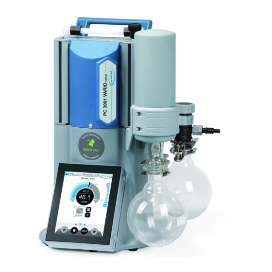
- Page 1 Technology for vacuum systems Chemistry pumping unit series PC 3001 VARIO select PC 3001 VARIO select TE PC 3001 VARIO select IK PC 3001 VARIO select EKP Instructions for use Original instructions EN-US 20901367...
- Page 2 Sales: +49 9342 808-5550 Service: +49 9342 808-5660 Fax: +49 9342 808-5555 Email: info@vacuubrand.com Web: www.vacuubrand.com Thank you for purchasing this product from VACUUBRAND GMBH + CO KG. You have chosen a modern and techni- cally high quality product. 20901367_EN-US_PC3001 VARIO select Serie_V1.3_100720...
-
Page 3: Table Of Contents
TABLE OF CONTENTS About this document 1.1 User information............. 5 1.2 Manual structure ............6 1.3 Display conventions ............7 1.4 Symbols and icons ............8 1.5 Instructions..............9 1.6 Abbreviations ..............9 1.7 Term definitions..............11 Safety information 2.1 Usage................12 2.1.1 Intended use ............12 2.1.2 Improper use............13 2.1.3 Foreseeable misuse ..........13... - Page 4 4.3.4 Dry ice condenser..........34 4.3.5 Venting connection ..........37 4.3.6 Gas ballast (GB) ............39 4.4 Electrical connection ............40 Commissioning (operation) 5.1 Switch on................42 5.2 Operation ...............43 5.2.1 User interface ............43 5.2.2 Operation ...............45 5.2.3 Operation with gas ballast ........46 5.3 Shutdown (switch off).............47 5.4 Storage................48 Troubleshooting 6.1 Technical support............49...
-
Page 5: About This Document
About this document About this document This is part of the product you have purchased. ® This manual, in conjunction with the VACUU·SELECT manual, applies to all versions of the pumping unit and is intended in par- ticular for laboratory staff. 1.1 User information Safety Instructions for use... -
Page 6: Manual Structure
About this document When contacting our Service Department, please have the serial number and product type at hand -> see the rating plate on the product. 1.2 Manual structure Breakdown of in- The manual has a modular structure with separate individual in- structions struction modules for the ... -
Page 7: Display Conventions
About this document 1.3 Display conventions Warning levels Display of warning DANGER levels Warns of an imminent hazard. Disregarding the situation could result in extremely seri- ous injury or death. Take appropriate action to avoid dangerous situa- Ø tions! WARNING Warns of a potentially hazardous situation. -
Page 8: Symbols And Icons
About this document 1.4 Symbols and icons This manual uses symbols and icons. Safety symbols indicate specific risks associated with handling the product. Symbols and icons are designed to help you identify risks more easily. Safety symbols Explanation General danger sign. Danger: electricity. -
Page 9: Instructions
About this document 1.5 Instructions Instruction (single step) ð Perform the step described. Instructions Result of action Instruction (multiple steps) 1. First step 2. Next step Result of action Carry out instructions requiring multiple steps in the order de- scribed. Instruction (graphic description) -> Example Schematic diagram... - Page 10 About this document Outlet (exhaust, exit), exhaust gas connection ATEX equipment labeling Fluoroelastomer Gas ballast Size Inlet condenser Inlet, vacuum connection Small flange max. Maximum value min. Minimum value without EK Without vapor condenser Polyamide Polybutylene terephthalate PC … Chemistry pumping unit with type identification number Polyethylene RMA no.
-
Page 11: Term Definitions
Dry ice con- Cooling condenser mounted at the outlet (pressure denser side) with receiving flask and dry ice as coolant. ® VACUU·BUS Bus system from VACUUBRAND for communication ® of peripheral devices with VACUU·BUS -enabled gauges and controllers. ® ®... -
Page 12: Safety Information
Safety information Safety information The information in this chapter must be observed by everyone who works with the product described here. The safety information applies to the entire life cycle of the equipment. 2.1 Usage Only use the product if it is in perfect working condition. 2.1.1 Intended use Intended use A chemistry pumping unit of product series PC 3001 VARIO se-... -
Page 13: Improper Use
Safety information 2.1.2 Improper use Improper use Incorrect use or any application which does not correspond to the technical data may result in injury or damage to property. Improper use includes: using the product contrary to its intended use, operation under inadmissible environmental and operating conditions, operation despite obvious errors or defective safety devices, unauthorized extensions or conversions, in particular when... -
Page 14: Obligations
Safety information 2.2 Obligations Operator obligations Operator obliga- The owner defines the responsibilities and ensures that only tions trained personnel or specialists work on the vacuum system. This applies in particular to connection, installation and mainte- nance work and troubleshooting. g ... -
Page 15: General Safety Information
ð When handling chemicals, wear your personal protective equipment. 3 see also Homepage: VACUUBRAND > Support > Instructions for repair 4 Alternatively, arrange for decontamination by a qualified service provider. 20901367_EN-US_PC3001 VARIO select Serie_V1.3_100720... -
Page 16: Safety Precautions
Safety information 2.6 Safety precautions ð Use your vacuum equipment only if you have understood its Safety precautions function and this manual. ð Replace defective parts immediately, e.g., a broken power cord, faulty hoses or faulty flasks. ð Use only original accessories and components which are designed for the vacuum technology, such as a vacuum hose, separator, vacuum valve, etc. -
Page 17: Possible Sources Of Danger
Safety information Possible protective measures ð Purge the vacuum pump with inert gas or air before chang- Protective mea- sures, depending ing the medium to be pumped. on application ð Use inert gas to dilute critical mixtures. ð Prevent the release of hazardous, toxic, explosive, corro- sive fluids, gases or vapors or those that are harmful to health or the environment, for example, through suitable laboratory facilities with a fume hood and ventilation control. - Page 18 Safety information ð Be aware of the max. pressures at the inlet and outlet of the pump as well as the max. admissible differential pressure between the inlet and outlet, according to the technical data. ð The system to be evacuated as well as all hose connections must be mechanically stable.
- Page 19 Safety information Hazards due to hot surfaces or overheating Surface tempera- The surface of vacuum pumps can reach temperatures > 70 °C tures during operation, in particular when pumping out heated media. ð Avoid direct contact with the surface. ð Use protection against accidental contact if the surface tem- perature is regularly elevated.
-
Page 20: Motor Protection
Safety information Dry ice must not be used in gas-tight containers. Do not secure the cover on the dry ice condenser. Pressure equalization be- tween coolant and the atmosphere must be ensured at all times. Keep signs legible Labels and signs Keep any signs affixed to the device in an easily readable condi- tion: ð... -
Page 21: Disposal
Safety information ATEX equipment The ATEX equipment category of the device is dependent on category and pe- the connected components and peripheral devices. Compo- ripheral devices nents and peripheral devices need to have the same or higher ATEX approval. Prevent ignition The use of venting valves is only permitted if this would not nor- sources mally, or only rarely, cause explosive mixtures in the interior of... -
Page 22: Product Description
Product description Product description Pumping units of the PC 3001 VARIO select series essentially consist of a diaphragm pump controlled by VARIO drive, a ® VACUU·SELECT type vacuum controller and a chiller with sep- arator. There are different versions of chiller. The difference lies in how the chillers operate. -
Page 23: Chemistry Pumping Unit Series
3.2 Chemistry pumping unit series Overview of chem- istry pumping units Description Chemistry pumping unit PC 3001 VARIO select ● ● PC 3001 VARIO select TE ● ● PC 3001 VARIO select IK ● ● PC 3001 VARIO select EKP ●... -
Page 24: Condensers And Chillers
Product description 3.3 Condensers and chillers 3.3.1 Separator/condenser at the inlet Connection at the separator flask Connections on the Description 1 Inlet connection vacuum IN Connection and coolant on the inlet condenser Connections on the Description 1 Inlet connection vacuum IN 2 Inlet connection coolant IN, e.g., water 3 Coolant outlet connection EX 20901367_EN-US_PC3001 VARIO select Serie_V1.3_100720... -
Page 25: Condenser At The Outlet
Product description 3.3.2 Condenser at the outlet Connection and coolant on the vapor condenser Connections on the Description 1 Coolant outlet connection EX 2 Inlet connection coolant IN, e.g., water 3 Outlet connection EX Connection and coolant on the dry ice condenser Connections on the PC 3001 VARIO select TE... - Page 26 Product description ® Connections at the Peltronic vapor condenser Connections on the 1 Outlet connection EX 2 Vacuum pump connection ® 3 VACUU·BUS port 4 Power supply with ON/OFF switch ® ð For detailed information and descriptions of the Peltronic por condenser -> see EK Peltronic...
-
Page 27: Sample Application
Product description 3.4 Sample application Evaporation -> Example Rotary evaporation Description PC 3001 VARIO select vacuum pumping unit Exhaust gas hose (diverted into a fume hood) Chiller Vacuum hose Coolant hoses (connected in series) Example: rotary evaporator Vacuum concentrator -> Example Vacuum concentra- Description PC 3001 VARIO select TE vacuum pumping unit Exhaust gas hose (diverted into a fume hood) Vacuum hose Vacuum valve: shut-off valve... -
Page 28: Installation And Connection
Installation and connection Installation and connection 4.1 Transport Products from VACUUBRAND are packed in sturdy, recyclable packaging. The original packaging is accurately matched to your product for safe transport. ð If possible, please keep the original packaging, e.g., for re- turning the product for repair. -
Page 29: Installation
Installation and connection 4.2 Installation NOTICE Condensate can damage the electronics. A large temperature difference between the storage location and the installation location can cause condensation. ð After goods receipt or storage, allow your vacuum device to acclimatize for at least 3-4 hours before initial use. Check installation conditions Calibrate for instal- The device is acclimatized. -
Page 30: Connection
Installation and connection Observe limitation of use Ambient conditions Ambient conditions (US) Ambient temperature 10–40 °C 50‑104°F Altitude, max. 2000 m 6562 ft above sea level above sea level Relative humidity 30–85 %, non condensing Pollution degree Impact energy 5 J Protection class (IEC 60529) IP 20 Type of protection(UL 50E) Type 1... - Page 31 Installation and connection NOTICE Foreign bodies in the suction line can damage the vacuum pump. ð Prevent particles, liquids or contaminants from being aspi- rated or being able to flow back. Connect the vacuum hose -> Example Vacuum connection at the inlet IN 1.
-
Page 32: Exhaust Gas Connection (Ex)
Installation and connection 4.3.2 Exhaust gas connection (EX) WARNING Risk of bursting due to overpressure inside the outlet line. Inadmissibly high pressure in the outlet line can cause the vacuum pump to burst or damage seals. The outlet line (outlet, gas outlet) must always be Ø... -
Page 33: Coolant Connection At The Condenser
Installation and connection 4.3.3 Coolant connection at the condenser Coolant connection A vapor condenser (EK) has a connection for coolant. For ex- IN = feed line ample, water or liquid in a chiller circuit is suitable for cooling. EX = outlet In a closed, in-house coolant circuit, the pressure should be limited to 3 bar (44 psi). -
Page 34: Dry Ice Condenser
Installation and connection 4.3.4 Dry ice condenser NOTICE Damage to the dry ice condenser due to cryogenic substances. ð Carry out a visual inspection prior to each use. Glass sur- faces must be free from damage, ruptures, cracks and scratches. ð... - Page 35 Installation and connection Fill the dry ice condenser CAUTION Risk of injury when handling cryogenic coolants. Cryogenic substances can cause frostbite, or ‘cold burns’, on contact with skin. Avoid skin contact and always wear your personal Ø protective equipment, e.g., thermal protective gloves, protective goggles, when handling cryogenic sub- stances.
- Page 36 Installation and connection Empty the dry ice condenser TE Before refilling the dry ice condenser with coolant, it may need to be emptied first. Remove the chiller insert (bayonet fastener) and empty it. -> Example Chiller insert (bayo- net fastener) 1. Remove the cover from 2.
-
Page 37: Venting Connection
Installation and connection 4.3.5 Venting connection DANGER Risk of explosion by venting with air. Depending on the application, venting can cause explo- sive mixtures to form or other hazardous situations to arise. Never vent processes with air which could form an Ø... - Page 38 Installation and connection Vent with inert gas – connect venting valve Required connection material: Hose for hose nozzle (Ø 4– 5 mm), e.g., silicone tube 3/6 mm. Position of sensor + inert gas venting valve (sectional dia- gram) 1. Slightly tilt the pumping unit to one side and push hose (c) onto the connection of venting valve (b).
-
Page 39: Gas Ballast (Gb)
Installation and connection 4.3.6 Gas ballast (GB) Use ambient air as gas ballast Gas ballast valve position If ambient air is to be used as gas ballast, nothing needs to be connected at the pumping unit; gas ballast valve (a); see also g Operation with gas ballast on page 46 chapter: Use of inert gas as gas ballast –... -
Page 40: Electrical Connection
Installation and connection 4.4 Electrical connection Pumping unit electrical connection -> Example Pumping unit elec- trical connection 1. Plug connector (a) of the power cord into the power connec- tion of the vacuum pump. 2. Plug power plug (b) into the power outlet. Pumping unit connected electrically. - Page 41 Installation and connection NOTICE! . ð Use the power plug which fits your power connection. ð Do not use multiple sockets connected in series as the power connection. ð The power plug also serves as a disconnector. Install the unit so that the plug can be easily disconnected from it. 20901367_EN-US_PC3001 VARIO select Serie_V1.3_100720...
-
Page 42: Commissioning (Operation)
1. Switch rocker switch (a) on – switch position I. 2. Press ON/OFF button (b) on the controller. The start screen is displayed. After approx. 30 seconds, the process screen with the operating elements appears on the controller display. WEB: VACUUBRAND/Products/Gauges and controllers/Vacuum control 20901367_EN-US_PC3001 VARIO select Serie_V1.3_100720... -
Page 43: Operation
Commissioning (operation) 5.2 Operation 5.2.1 User interface User interface ® VACUU·SELECT with process screen Process screen Pressure display for a process 1 Status bar 2 Analogue pressure display – pressure curve 3 Digital pressure display – pressure value (target value, actual value, pressure unit) 4 Process screen with context features 5 Screen navigation... - Page 44 Commissioning (operation) Operating elements Operating elements Button Function Vacuum controller Start Start application – only available on the process screen. Stop Stop application – always possible. VENT – Vent the system (option) Press button < 2 sec = vent briefly; control contin- ues. Press button > 2 sec = vent to atmospheric pres- sure;...
-
Page 45: Operation
Commissioning (operation) 5.2.2 Operation Start the vacuum controller Start Stop the vacuum controller Stop Vent Vent 20901367_EN-US_PC3001 VARIO select Serie_V1.3_100720... -
Page 46: Operation With Gas Ballast
Commissioning (operation) 5.2.3 Operation with gas ballast Description The provision of gas ballast (= addition of gas) ensures that va- pors do not condense inside the vacuum pump but are instead ejected from the pump. This makes it possible to pump larger amounts of condensable vapors, and also prolongs the service life. -
Page 47: Shutdown (Switch Off)
Commissioning (operation) 5.3 Shutdown (switch off) Shut down the pumping unit Switch off pumping 1. Stop the process and let the pumping unit run on for about unit 30 minutes, with open gas ballast or open inlet (IN). Condensate and media residues will be flushed out of the vacuum pump. -
Page 48: Storage
Commissioning (operation) 5.4 Storage Store the pumping unit 1. Clean the pumping unit if required. 2. Recommendation: Perform preventative maintenance be- fore storing the pumping unit. This is especially important if it ran more than 15,000 operating hours. 3. Close the suction and outlet lines, e.g., with the transport caps. -
Page 49: Troubleshooting
Troubleshooting Troubleshooting 6.1 Technical support g Error – Cause – Remedy For troubleshooting, refer to table on page 49. For technical assistance or in the event of an error, please con- tact our Service department. Only use the device if it is in perfect working condition. ð... - Page 50 Troubleshooting Error Cause Remedy Personnel Venting valve does Venting valve in Replace defective Specialist not operate sensor defective. components. Vacuum pump does Pumping unit Switch on Pumping Operator not start switched off. unit. Power plug not cor- Check power con- rectly plugged in or nection and cable.
- Page 51 Troubleshooting Error Cause Remedy Personnel No or very little suc- Deposits inside the Clean and check Specialist tion power vacuum pump. pump heads. Diaphragms or Replace di- valves defective. aphragms and High level of vapor valves. generated in the Check process pa- process.
-
Page 52: Cleaning And Maintenance
Cleaning and maintenance Cleaning and maintenance WARNING Danger due to electrical voltage. Switch the device off before cleaning or maintenance Ø work. Unplug the power plug from the socket. Ø Risk from contaminated parts. Pumping hazardous media can result in hazardous sub- stances adhering to internal parts of the pump. -
Page 53: Information On Service Work
Cleaning and maintenance 7.1 Information on service work Recommended maintenance intervals Maintenance inter- Maintenance intervals As required 15,000 h vals Replace diaphragms Replace valves Clean or replace molded PTFE hose Replace pressure relief valve on EK Cleaning the pumping unit Recommended aids -> Example Recommended aids for cleaning and... - Page 54 Cleaning and maintenance Tools needed for maintenance -> Example Tools Description No. Tool Size 1 Flat-head screwdriver To open hose clips Size 1 2 Torx screwdriver Screw fittings, counterhold EK or IK TX10 3 Open-end wrench M14 union nut SW17 Rotate angled screw fitting SW14 4 Phillips screwdriver Screw fittings, holder TE or EKP...
-
Page 55: Cleaning
Cleaning and maintenance 7.2 Cleaning This chapter does not contain descriptions for decontamination of the product. This chapter describes simple measures for cleaning and care. ð Before cleaning, switch off the pumping unit. 7.2.1 Housing surface Clean the surfaces Clean dirty surfaces with a clean, slightly damp cloth. We rec- ommend using water or mild soapy water to moisten the cloth. -
Page 56: Clean The Sensor And Venting Valve
Cleaning and maintenance 7.2.3 Clean the sensor and venting valve In case of incorrect measurements or malfunctions that indicate contamination of the sensor and/or venting valve, we recom- mend cleaning the sensor and the venting valve. Cleaning is also recommended prior to re-calibration. Remove the sensor -> Example Remove the sensor... - Page 57 Cleaning and maintenance 4. Close the hose nozzle of 5. Open the union nut on the the chiller and carefully sensor, open-end wrench turn the pumping unit up- SW17, and pull off the side down. molded hose. -> Example Remove the sensor 6.
- Page 58 Cleaning and maintenance Install the sensor -> Example Fit the sensor 1. Connect the VACUU·BUS 2. Insert the screws and connector and place the screw them in until they sensor on the holder. are finger-tight, hex key size 3. 3. Push the molded hose 4.
-
Page 59: Clean Or Replace Ptfe Hoses
Cleaning and maintenance 7.2.4 Clean or replace PTFE hoses Maintenance provides the opportunity to check the components of the pumping unit, including the hoses. ð Clean the inside of very dirty molded hoses, e.g., using a pipe cleaner or similar. ð Replace brittle and defective molded hoses. 7.3 Vacuum pump maintenance 7.3.1 Maintenance items Positions to be maintained... - Page 60 Cleaning and maintenance Exploded drawing of pump head (example) -> Example Exploded drawing of pump head Description Valve maintenance 1 Screw fittings 2 Housing cover 3 Valves Diaphragm maintenance 4 Head cover 5 Diaphragm clamping disc with square head screw 6 Diaphragms 7 Diaphragm support disc 8 Spacer discs, max.
-
Page 61: Change The Diaphragms And Valves
Cleaning and maintenance 7.3.2 Change the diaphragms and valves Preparation -> Example Prepare for mainte- nance 1. Switch the pumping unit 2. Remove the glass flasks off and unplug the power and connected hoses plug. (coolant, vacuum). -> Example Remove the EK (IK) 3. - Page 62 Cleaning and maintenance 5. Unscrew the union nut and 6. Remove the chiller. pull off the molded hose. 7. Set the chiller down se- curely so that no liquid can escape. Remove the TE or EKP -> Example Remove the dry ice condenser (TE) or Peltronic vapor con- denser (EKP)
- Page 63 Cleaning and maintenance Disassemble the device and housing sections -> Example Remove the hous- ing sections on the left 1. Loosen the union nut; 2. Rotate the angled screw open-end wrench SW17. fitting to one side by a quarter turn; open-end wrench SW14.
- Page 64 Cleaning and maintenance -> Example Remove the hous- ing sections on the left 7. Lift off the housing cover 8. Check for adhered valves and pull off the molded and place the housing hose. cover with the screw fit- tings to one side. 9.
- Page 65 Cleaning and maintenance Replace diaphragms -> Example Diaphragm replace- ment 1. Fold the diaphragm up at 2. Carefully position the di- the sides. aphragm wrench on the di- aphragm support disc. 3. Use the secured di- 4. Lift the diaphragm, along aphragm wrench to un- with all the parts, out of screw the assembly.
- Page 66 Cleaning and maintenance Never drop spacer discs 5. Disassemble the assembly into the aluminum housing. and take a new di- aphragm; service kit Check for any spacer discs MD 1C. adhering to the connecting rod. Keep the spacer discs. It is essential to reinsert the same number of spacer discs.
- Page 67 Cleaning and maintenance 8. Secure the diaphragm as- 9. Hold the spacer discs sembly inside the di- firmly and place the as- aphragm wrench. sembly on the connecting rod thread. 10. Tighten the assembly until 11. Repeat for the second di- finger-tight, using the di- aphragm.
- Page 68 Cleaning and maintenance Change valves -> Example Valve replacement 1. Carefully clean dirty head 2. housing covers with a covers and cloth. 3. Place both head covers in 4. Position the new valves the correct position. and align them; service kit MD 1C.
- Page 69 Cleaning and maintenance -> Example Valve replacement 6. Position the housing cover so that it is level and screw in the screw fittings; hex key size 4, tightening torque 6 Nm. 20901367_EN-US_PC3001 VARIO select Serie_V1.3_100720...
- Page 70 Cleaning and maintenance Assemble the device and housing sections Before restarting the pumping unit, all previously removed parts of the device and housing must be fixed back in place. -> Example Mount the device and housing sec- tions 1. Set the pumping unit up- 2.
- Page 71 Cleaning and maintenance 5. Secure open hose clips 6. Push on the molded hose using flat nose pliers. and screw on the union nut until it is finger-tight. 7. Secure the counter holder; 8. Secure the glass flasks Torx screwdriver TX10. with the joint clamp.
- Page 72 Cleaning and maintenance Diaphragm and valve replacement, next pump head -> Example 1. Turn the the pumping unit Second pump head to the other side. maintenance 2. Repeat the above steps for diaphragm and valve replacement. If maintenance work has been completed in full: ð...
-
Page 73: Appendix
Appendix 8.1 Technical data Product designation Product names Chemistry pumping unit series PC 3001 VARIO select PC 3001 VARIO select PC 3001 VARIO select TE PC 3001 VARIO select TE Technical data Technical data Ambient conditions (US) Ambient temperature 10–40 °C 50‑104°F... - Page 74 Appendix Inert gas adapter – OPTION Small flange GB NT KF DN 16 Hose nozzle GB NT DN 6/10 Venting valve (venting with inert Silicone rubber hose 3/6 gas) – OPTION Coolant EK (+IK) 2x (+2x ) hose nozzles DN 6/8 Exhaust gas, outlet EX Hose nozzle DN 8/10 Cold connector...
-
Page 75: Wetted Materials
Appendix Weights* and dimensions (l x w x h) (US) PC 3001 VARIO select 303 mm x 306 mm 12.05 in x x 400 mm 11.93 in x 15.75 in Weight* 8,2 kg 18.08 lb PC 3001 VARIO select 300 mm x 341 mm 11.81 in x 13.43 in x x 493 mm 19.41 in Weight* 8,7 kg 19.18 lb PC 3001 VARIO select 309 mm x 312 mm 12.17 in x 12.28 in x x 400 mm... -
Page 76: Rating Plate
Appendix Distributor head (inlet) PPS glass fiber reinforced, PP (blind plate) Condenser IK, EK, TE Borosilicate glass Round bottom flask Borosilicate glass Peltronic vapor condenser ETFE, ECTFE, PP, PA Silencer PBT, PVF, rubber VACUU·SELECT Sensor Vacuum sensor Aluminum oxide ceramic, goldplated Measurement chamber Small flange OPTION Sealing ring at the sensor... -
Page 77: Ordering Information
Chemistry pumping unit series *Order no. tion for pumping PC 3001 VARIO select 2070020x units PC 3001 VARIO select TE 2070022x PC 3001 VARIO select IK 2070026x PC 3001 VARIO select EKP 2070024x * Order no. depends on power cord CEE, CH, UK, US, CN, IN... -
Page 78: Service Information
Appendix 20676021 20635997 20635365 20612065 20612058 ð VACUUBRAND > Support > Instructions for repair > Chem- istry pumping units. Sources of supply International sales Purchase original accessories and original spare parts from a offices and distribu- subsidiary of VACUUBRAND GMBH + CO KG or your local dis- tion tributor. - Page 79 Appendix Service handling Follow these headings: VACUUBRAND > Support > Service Reduce downtime, speed up processing. Please have the required data and documents at hand when contacting our Service Depart- ment. ð Your order can be quickly and easily processed. ð Hazards can be prevented.
-
Page 80: Eu Declaration Of Conformity
Appendix 8.6 EU Declaration of Conformity 20901367_EN-US_PC3001 VARIO select Serie_V1.3_100720... -
Page 81: Index
Display conventions...... 7 Disposal ........ 21 PC 3001 VARIO select .... 23 Dry ice chiller ...... 23 PC 3001 VARIO select EKP .. 23 Dry ice condenser....... 23 PC 3001 VARIO select IK... 23 PC 3001 VARIO select TE.. 23 Peltronic vapor condenser .. 23 Empty the dry ice condenser TE. 36 Peltronic®... - Page 82 Index Recommended aids for cleaning and maintenance .... 53 Remove EK (IK) (example)... 61 Remove EKP (Peltronic vapor con- denser) ........ 62 Remove TE (dry ice condenser) . 62 Responsibility matrix.... 15 Rough vacuum...... 11 Safety information....... 12 Safety precautions ...... 16 Separator flask...... 23 Separator flask connections .. 24 Surface temperatures .... 19 Switch on ........ 42 Switch on pumping unit.... 42...
- Page 83 20901367_EN-US_PC3001 VARIO select Serie_V1.3_100720...
- Page 84 Technology for vacuum systems Manufacturer: VACUUBRAND GMBH + CO KG Alfred‑Zippe‑Str. 4 97877 Wertheim GERMANY Phone: Switch- +49 9342 808-0 board: Sales: +49 9342 808-5550 Service: +49 9342 808-5660 Fax: +49 9342 808-5555 Email: info@vacuubrand.com Web: www.vacuubrand.com...
Need help?
Do you have a question about the PC 3001 VARIO select and is the answer not in the manual?
Questions and answers