
Subscribe to Our Youtube Channel
Related Manuals for vacuubrand PC 3001 VARIO select


Summary of Contents for vacuubrand PC 3001 VARIO select
- Page 1 Chemistry pumping unit series PC 3001 VARIO select PC 3001 VARIO select TE PC 3001 VARIO select IK PC 3001 VARIO select EKP Instructions for use Original instructions EN-US 20901367...
- Page 2 Head office: +49 9342 808-0 Sales: +49 9342 808-5550 Service: +49 9342 808-5660 Fax: +49 9342 808-5555 E-mail: info@vacuubrand.com Web: www.vacuubrand.com Thank you for purchasing this product from VACUUBRAND GMBH + CO KG. You have chosen a state-of-the-art, high-quality prod- uct. 20901367_EN-US_PC3001 VARIO select Serie_V1.6_131022...
-
Page 3: Table Of Contents
TABLE OF CONTENTS About this manual User information ..............6 Instruction manual layout ............. 7 Presentation conventions............8 Symbols and pictograms ............9 Action instructions ..............10 Abbreviations ................. 10 Explanation of terms.............. 12 Safety instructions Use ..................13 2.1.1 Proper use.............. - Page 4 4.3.2 Exhaust connection (OUT) ..........35 4.3.3 Coolant connection on the condenser......36 4.3.4 Dry ice condenser ............37 4.3.5 Venting connection ............39 4.3.6 Gas ballast (GB) ............. 42 Electrical connection ............. 43 Operation Switching on................46 Operation with controller ............47 5.2.1 Operator interface............
- Page 5 Keyword Index 20901367_EN-US_PC3001 VARIO select Serie_V1.6_131022...
-
Page 6: About This Manual
About this manual About this manual This User manual is part of the pumping unit you have purchased. This instruction manual is valid for all pumping unit models, to- gether with the instruction manual of the VACUU SELECT controller, and is intended specifically for operators. 1.1 User information Safety Instruction manual... -
Page 7: Instruction Manual Layout
In case of an incomplete User manual, you can request a re- placement from us. Alternatively, our download portal is avail- able to you: www.vacuubrand.com Call us or write to us if you have any other questions about the product, need additional information or want to give us feed- back on the product. -
Page 8: Presentation Conventions
About this manual 4 Optional instruction manual: Accessories 1.3 Presentation conventions Warning messages Presentation of DANGER warning messages Warning of imminent danger. Failure to observe this warning may result in imminent danger to life or severe injury. Please follow the instructions for prevention! Ø... -
Page 9: Symbols And Pictograms
About this manual 1.4 Symbols and pictograms This instruction manual uses symbols and pictograms. These safety symbols and pictograms indicate specific dangers or requirements when handling the product. Warning signs with safety symbols on the product provide a visualization of the potential hazard. Safety symbols Explanation of General danger sign. -
Page 10: Action Instructions
About this manual 1.5 Action instructions Action instructions (simple) Action instructions ð You are requested to take action. Result of the action Action instructions (multiple steps) 1. First action step 2. Next action step Result of the action Action instructions that require several steps must be followed in the order they are described. - Page 11 About this manual Peltronic emission condenser or Peltronic EK Outlet (exhaust, exit), exhaust gas connection ATEX device marking Fluoropolymer rubber Gas type ind. Gas type independent Gas ballast If necessary If necessary Size Size Immission condenser Inlet, vacuum connection Small flange Max.
-
Page 12: Explanation Of Terms
Dry ice condenser Cooling condenser with receiving flask and dry ice as cooling medium installed at the outlet (pressure side). VACUU·BUS VACUUBRAND bus system for the communication of pe- ripheral devices with VACUU BUS-capable measuring equipment and controllers. VACUU·BUS ad-... -
Page 13: Safety Instructions
Safety instructions Safety instructions The information in this chapter must be observed by all persons who work with the device described here. The safety instructions are valid for all life stages of the product. 2.1 Use The device may only be used in perfect technical condition. 2.1.1 Proper use Proper use A chemistry pumping unit of the PC 3001 VARIO select product series... -
Page 14: Improper Use
Safety instructions 2.1.2 Improper use Improper use Improper use or any use that does not correspond with the technical data can lead to personal or material damage. Improper use is considered: use that contradicts the proper use, operation in unauthorized ambient and operating conditions, operation with obvious faults, damages or defective safety equipment, unauthorized extensions and modifications, especially when... -
Page 15: Responsibilities
Safety instructions 2.2 Responsibilities Follow the instructions for all actions as they are specified in this in- struction manual. Responsibilities of the operator Operator responsibil- The operator defines the responsibilities and ensures that only ities trained or qualified personnel work on the vacuum system. This ap- plies in particular to connection, assembly work, maintenance tasks and fault elimination. -
Page 16: General Safety Information
Decommissioning Decontamination 2.4 General safety information Quality standards Products of VACUUBRAND GMBH + CO KG are subject to high qual- and safety ity control requirements in terms of safety and operation. Each product is put through an extensive test program before delivery. Follow the instructions for all actions as they are specified in this in- struction manual. -
Page 17: Safety Measures
ð Wear your personal protection equipment when handling chemicals. 2.6 Safety measures Manufacturer mea- Products of VACUUBRAND GMBH + CO KG are subject to high qual- sures ity control requirements in terms of safety and operation. Each product is put through an extensive test program before delivery. - Page 18 Safety instructions Dangers posed by different substances Pumping different Pumping different substances or media can trigger a reaction be- substances tween materials. Work materials that leak into the vacuum pump with the gas flow can damage the vacuum pump. Hazardous substances can form de- posits in the vacuum pump.
-
Page 19: Possible Sources Of Danger
Safety instructions 2.8 Possible sources of danger Considering mechanical stability Observing mechani- Due to the high compression ratio of the pumps, a higher pressure cal stability can build up at the outlet than the mechanical stability of the sys- tem allows. ð... - Page 20 Safety instructions Dangers during ventilation Looking out for dan- Depending on the process, a potentially explosive mixture can form gers during ventila- in installations or other dangerous situations can occur. tion Dangers due to residual energy Possible residual en- After the vacuum pump has been switched off and disconnected ergies from the power network, dangers may still be present due to resid- ual energies:...
-
Page 21: Motor Protection
Safety instructions ð Remove the cover hood used as transport protection before you put the device into operation. ð Avoid applying too much heat due to hot process gases. ð Observe the maximum permissible media temperature accord- ing to the technical data. Handling coolants and cryogenic materials properly Proper handling of Cryogenic materials may cause frostbite (cold burns) when contact... -
Page 22: Atex Device Category
Safety instructions 2.10 ATEX device category Installation and explosive environment Installation and operation in areas where an explosive atmos- phere can occur in dangerous quantities is not permitted. The user is responsible for assessing the hazards for the device, so that any protection measures can be implemented for the installa- tion and safe operation. -
Page 23: Disposal
Safety instructions measuring non-explosive gases, extended gas suction tempera- tures apply, see chapter: Technical data, media temperature (gas). 2.11 Disposal NOTICE Improper disposal of electronic components can result in damage to the environment. Electronic equipment contains hazardous materials that can dam- age the environment or human health. -
Page 24: Product Description
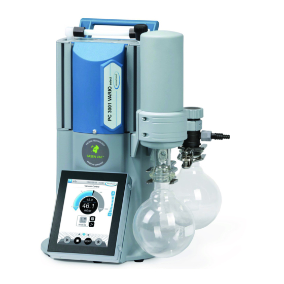
Product description Product description Pumping units of the PC 3001 VARIO select series essentially consist ® of membrane pump, regulated by VARIO drive, a VACUU·SELECT vacuum controller as well as a cooler with a separator. Coolers are available in different designs. The coolers differ in how they func- tion. -
Page 25: Chemistry Pumping Unit Series
3.2 Chemistry pumping unit series Overview of chem- istry pumping unit models Meaning Chemistry pumping unit PC 3001 VARIO select ● ● PC 3001 VARIO select TE ● ● PC 3001 VARIO select IK ● ● PC 3001 VARIO select EKP ● ●... -
Page 26: Condensers And Coolers
Product description 3.3 Condensers and coolers 3.3.1 Separator/condenser at inlet Connection on separator flask Connections on AK Meaning 1 Vacuum inlet connection IN Connection and coolant on the inlet condenser Connections on the Description 1 Inlet connection vacuum IN 2 Inlet connection coolant IN, e.g., water 20901367_EN-US_PC3001 VARIO select Serie_V1.6_131022... -
Page 27: Condenser At Outlet
Product description 3 Coolant outlet connection EX 3.3.2 Condenser at outlet Connection and coolant on emission condenser Connections on EK Meaning 1 Outlet connection coolant EX 2 Inlet connection coolant IN, e.g. water 3 Outlet connection EX Connection and coolant on the dry ice condenser Connections on the PC 3001 VARIO select TE... - Page 28 Product description 2 Outlet connection EX 3 Vacuum pump connection Connections on the Peltronic emission condenser Connections on EKP 1 Outlet connection EX 2 Vacuum pump connection 3 VACUU BUS connection 4 Power connection with on/off switch ð For detailed information and descriptions about the Peltronic emission condenser -> see the Peltronic EK...
-
Page 29: Application Example
Product description 3.4 Application example Evaporation -> Example Rotary evaporation Description PC 3001 VARIO select vacuum pumping unit Exhaust gas hose (diverted into a fume hood) Chiller Vacuum hose Coolant hoses (connected in series) Example: Rotary evaporation Vacuum concentrator -> Example Vacuum concentra- Description PC 3001 VARIO select TE vacuum pumping unit Exhaust gas hose (diverted into a fume hood) Vacuum hose Vacuum valve: shut-off valve... - Page 30 Product description Process example: Vacuum concentrator 20901367_EN-US_PC3001 VARIO select Serie_V1.6_131022...
-
Page 31: Installation And Connection
Installation and connection Installation and connection 4.1 Transport Products from VACUUBRAND are packaged in stable, recyclable packaging. The original packaging is customized to your product for safe transport. ð If possible, keep the original packaging, e.g. for sending in for re- pairs. -
Page 32: Installation
Installation and connection 4.2 Installation NOTICE Condensate can damage the electronics. A large difference in temperature between the storage location and the installation site can lead to the formation of condensate. ð After receipt or storage, allow your vacuum to acclimatize for at least 3–4 hours before putting it into operation. -
Page 33: Connection (Supply Connections)
Installation and connection Observing the limitations of use Ambient conditions Ambient conditions (US) Ambient temperature 10–40 °C 50–104°F Installation height, max. 2000 m 6562 ft above sea level above sea level Humidity 30–85 %, non-condensing Degree of contamination Impact energy 5 J Protection class (IEC 60529) IP 20 Protection class (UL 50E) Type 1... - Page 34 Installation and connection NOTICE Foreign bodies in the suction line can damage the vacuum pump. ð Prevent particles, liquids or contaminants from being vacu- umed or from being able to flow back. Connecting the vacuum hose -> Example Vacuum connection at inlet IN 1.
-
Page 35: Exhaust Connection (Out)
Installation and connection 4.3.2 Exhaust connection (OUT) WARNING Risk of bursting due to excess pressure in the ex- haust line. Unacceptably high pressure in the exhaust line may cause the vacuum pump to burst or damage seals. The exhaust line (outlet, gas outlet) must always be open Ø... -
Page 36: Coolant Connection On The Condenser
Installation and connection 4.3.3 Coolant connection on the condenser Coolant connection An emission condenser EK has one connection for coolants. Water or Inflow and outflow liquid in the circuit of a recirculating chiller, for example, is suitable for cooling. In a closed, internal coolant circuit, the pressure should be lim- ited to 3 bar (44 psi). -
Page 37: Dry Ice Condenser
Installation and connection 4.3.4 Dry ice condenser NOTICE Damage to the dry ice condenser due to cryogenic sub- stances. ð Carry out a visual inspection prior to each use. Glass surfaces must be free from damage, ruptures, cracks and scratches. ð... - Page 38 Installation and connection Fill the dry ice condenser CAUTION Risk of injury when handling cryogenic coolants. Cryogenic substances can cause frostbite, or ‘cold burns’, on contact with skin. Avoid skin contact and always wear your personal pro- Ø tective equipment, e.g., thermal protective gloves, pro- tective goggles, when handling cryogenic substances.
-
Page 39: Venting Connection
Installation and connection -> Example Chiller insert (bayo- net fastener) 1. Remove the cover from the 2. Rotate the chiller insert – chiller. bayonet fastener. 3. Pull out the chiller insert. 4. Empty the liquid. 5. Refit the empty chiller insert in the dry ice condenser in re- verse order. - Page 40 Installation and connection Vent with ambient air Position of sensor + venting valve sec- tional diagram For venting with ambient air, nothing needs to be connected to venting valve (b) of sensor (a). 6 Only applicable to sensors with an integrated venting valve. 20901367_EN-US_PC3001 VARIO select Serie_V1.6_131022...
- Page 41 Installation and connection Vent with inert gas – connect venting valve Required connection material: Hose for hose nozzle (Ø 4–5 mm), e.g., silicone tube 3/6 mm. Position of sensor + inert gas venting valve (sectional dia- gram) 1. Slightly tilt the pumping unit to one side and push hose (c) onto the connection of venting valve (b).
-
Page 42: Gas Ballast (Gb)
Installation and connection 4.3.6 Gas ballast (GB) Use ambient air as gas ballast DANGER Explosion risk due to air as gas ballast. By using air as a gas ballast, a small amount of oxygen en- ters the inside of the vacuum pump. Depending on the process, a potentially explosive mixture can form due to oxygen in the air, or other dangerous situations can occur. -
Page 43: Electrical Connection
Installation and connection ð Remove the black gas ballast cap and connect a gas ballast adapter in its place. On request, we can send you connection options and adapters for hose nozzles or small flanges. 4.4 Electrical connection Connecting the pumping unit to the electrical system -> Example Electrical connection of the pumping unit... - Page 44 Installation and connection Power connections with country code -> Example Diagrams of standard Power plug types power connections with ground contact 1 UK 2 CN 3 IND 4 US 5 CEE 6 CH The vacuum pump is delivered ready for use with the matching power plug.
- Page 45 Installation and connection -> Example Schematic drawing of controller with connected valve and sensors Accessories -> see chapter Ordering information 20901367_EN-US_PC3001 VARIO select Serie_V1.6_131022...
-
Page 46: Operation
1. Switch on the rocker switch (a) – switch position I. 2. Press the ON/OFF button (b) on the controller. Display with start screen. After approx. 30 seconds, the process display appears with the control elements in the display of the controller. WEB: VACUUBRAND/Produkte/Messgeräte und Controller/Vakuum regeln 20901367_EN-US_PC3001 VARIO select Serie_V1.6_131022... -
Page 47: Operation With Controller
Operation 5.2 Operation with controller 5.2.1 Operator interface Operator interface ® VACUU·SELECT with process display Process display Pressure display for a process 1 Status bar 2 Analog pressure display – pressure curve 3 Digital pressure display – pressure value (target value, actual value, pres- sure unit) 4 Process display with context functions 5 Screen navigation... - Page 48 Operation Controls Controls Button Function Vacuum controller Start Start an application – only in the process display Stop Stop an application – always possible. VENT – Ventilate system (Option) Button press < 2 Sec. = briefly ventilate, regulation continues. Button press > 2 Sec. = ventilate to atmospheric pres- sure, vacuum pump is stopped.
-
Page 49: Operation
Operation 5.2.2 Operation Starting the vacuum controller Start Stopping the vacuum controller Stop Ventilating Ventilating 20901367_EN-US_PC3001 VARIO select Serie_V1.6_131022... -
Page 50: Operation With Gas Ballast
Operation 5.2.3 Operation with gas ballast Meaning The supply from the gas ballast (= gas addition) ensures that vapors are not condensed in the vacuum pump; instead, they are emitted out of the pump. This allows greater amounts of condensable va- pors to be pumped, which extends the service life. -
Page 51: Switching Off (Decommissioning)
Operation 5.3 Switching off (decommissioning) Switching off the pumping unit Switching off, e.g. 1. Stop the process and allow the pumping unit to continue run- taking the pumping ning for approx. 30 minutes with open gas ballast or open inlet unit out of operation (IN). -
Page 52: Storage
Operation 5.4 Storage Storing the pumping unit 1. Clean the The pumping unit if it is dirty. 2. Recommendation: Carry out preventative maintenance before you put The pumping unit into storage. Especially if it has been in operation for more than 15,000 hours. 3. -
Page 53: Troubleshooting
Troubleshooting Troubleshooting 6.1 Technical assistance To find and eliminate errors, use the table g Error – cause – correc- tive measure on page 53. For technical assistance or in case of faults, please contact our Ser- vice department. The device should only be operated in perfect technical condition. ð... - Page 54 Troubleshooting Error Cause Corrective measure Personnel Use another external ventilation valve if necessary. Ventilation valve Ventilation valve sen- Replace defective Qualified does not switch sor defective. components. employee Vacuum pump does Pumping unit Switch on Pumping Operator not start switched off. unit.
- Page 55 Troubleshooting Error Cause Corrective measure Personnel Check the gas ballast cap. Replace defective components. No suction capacity Deposits in the vac- Clean and test pump Qualified or very little uum pump. heads. employee Membrane or valves Replace the mem- defective. brane and valves.
-
Page 56: Cleaning And Maintenance
Cleaning and maintenance Cleaning and maintenance WARNING Danger due to electrical voltage. Switch off the device before cleaning or maintenance. Ø Disconnect the power plug from the power outlet. Ø Danger due to contaminated components. When pumping dangerous media, hazardous materials can adhere to interior pump components. -
Page 57: Information On Service Activities
Cleaning and maintenance 7.1 Information on service activities Recommended maintenance interval Maintenance inter- Maintenance intervals As required 15,000 h vals Replace membranes Replace valves Clean or replace PTFE molded hose Replace pressure release valve on EK Clean pumping unit Recommended auxiliary equipment ->Example Recom- mended auxiliary equipment for clean-... - Page 58 Cleaning and maintenance Tools needed for maintenance -> Example Tools Meaning No. Tool Size 1 Flat-head screwdriver Opening hose clamps Size 1 2 Torx screwdriver Screw fasteners for EK or IK counterholder TX10 3 Open-end wrench Union nut M14 SW17 Rotate elbow fitting SW14 4 Phillips-head screwdriver Screw fasteners for TE or EKP bracket...
-
Page 59: Cleaning
Cleaning and maintenance 7.2 Cleaning This chapter does not describe how to decontaminate the product. Simple cleaning and care measures are described here. ð Before cleaning, switch off the pumping unit. CAUTION Risk of burning due to hot surfaces An elevated exhaust gas temperature can lead to hot sur- faces on the instrument and on attached components, such as glass flasks. -
Page 60: Emptying The Glass Flask
Cleaning and maintenance 7.2.2 Emptying the glass flask Removing and emptying the glass flask -> Example Emptying the glass flask 1. Open the joint clamp and re- 2. Empty the glass flask into a move the glass flask. suitable container, e.g. a chemical-resistant canister. - Page 61 Cleaning and maintenance Remove the sensor -> Example Remove the sensor 1. Switch the pumping unit off 2. Remove the vacuum con- and unplug the power plug. troller from the housing and disconnect any connected VACUU·BUS connectors. 3. Remove the glass flasks and place them on suitable stands. 4.
- Page 62 Cleaning and maintenance -> Example Remove the sensor 6. Undo the screws, hex key 7. Disconnect the VACUU·BUS size 3 connector at the bottom and remove the sensor. Clean the sensor -> Example Clean the measure- ment chamber and the venting valve 1. Use a pipette to fill a small 2.
- Page 63 Cleaning and maintenance Install the sensor -> Example Fit the sensor 1. Connect the VACUU·BUS 2. Insert the screws and screw connector and place the them in until they are finger- sensor on the holder. tight, hex key size 3. 3. Push the molded hose onto 4.
-
Page 64: Cleaning Or Replacing Ptfe Molded Hoses
Cleaning and maintenance 7.2.4 Cleaning or replacing PTFE molded hoses Maintenance provides an opportunity to check the components of the pumping unit, including the hosing. ð Clean the inside of highly soiled molded hoses, e.g. with a pipe cleaner or similar. ð... - Page 65 Cleaning and maintenance Exploded drawing of pump head (example) -> Example Exploded drawing of pump head Description Valve maintenance 1 Screw fittings 2 Housing cover 3 Valves Diaphragm maintenance 4 Head cover 5 Diaphragm clamping disc with square head screw 6 Diaphragms 7 Diaphragm support disc 8 Spacer discs, max.
-
Page 66: Change The Diaphragms And Valves
Cleaning and maintenance 7.3.2 Change the diaphragms and valves Preparation -> Example Prepare for mainte- nance 1. Switch the pumping unit off 2. Remove the glass flasks and and unplug the power plug. connected hoses (coolant, vacuum). -> Example Remove the EK (IK) 3. - Page 67 Cleaning and maintenance 5. Unscrew the union nut and 6. Remove the chiller. pull off the molded hose. 7. Set the chiller down se- curely so that no liquid can escape. Remove the TE or EKP -> Example Remove the dry ice condenser (TE) or Peltronic vapor con- denser (EKP)
- Page 68 Cleaning and maintenance Disassemble the device and housing sections -> Example Remove the housing sections on the left 1. Loosen the union nut; open- 2. Rotate the angled screw fit- end wrench SW17. ting to one side by a quarter turn; open-end wrench SW14.
- Page 69 Cleaning and maintenance -> Example Remove the housing sections on the left 7. Lift off the housing cover 8. Check for adhered valves and pull off the molded and place the housing cover hose. with the screw fittings to one side. 9.
- Page 70 Cleaning and maintenance Replace diaphragms -> Example Diaphragm replace- ment 1. Fold the diaphragm up at 2. Carefully position the di- the sides. aphragm wrench on the di- aphragm support disc. 3. Use the secured diaphragm 4. Lift the diaphragm, along wrench to unscrew the as- with all the parts, out of the sembly.
- Page 71 Cleaning and maintenance Never drop spacer discs into 5. Disassemble the assembly the aluminum housing. and take a new diaphragm; service kit MD 1C. Check for any spacer discs adhering to the connecting rod. Keep the spacer discs. It is essential to reinsert the same number of spacer discs.
- Page 72 Cleaning and maintenance 8. Secure the diaphragm as- 9. Hold the spacer discs firmly sembly inside the di- and place the assembly on aphragm wrench. the connecting rod thread. 10. Tighten the assembly until 11. Repeat for the second di- finger-tight, using the di- aphragm.
- Page 73 Cleaning and maintenance Change valves -> Example Valve replacement 1. Carefully clean dirty head 2. housing covers with a cloth. covers and 3. Place both head covers in 4. Position the new valves and the correct position. align them; service kit MD 1C.
- Page 74 Cleaning and maintenance -> Example Valve replacement 6. Position the housing cover so that it is level and screw in the screw fittings; hex key size 4, tightening torque 6 Nm. 20901367_EN-US_PC3001 VARIO select Serie_V1.6_131022...
- Page 75 Cleaning and maintenance Assemble the device and housing sections Before restarting the pumping unit, all previously removed parts of the device and housing must be fixed back in place. -> Example Mount the device and housing sections 1. Set the pumping unit up- 2.
- Page 76 Cleaning and maintenance 5. Secure open hose clips us- 6. Push on the molded hose ing flat nose pliers. and screw on the union nut until it is finger-tight. 7. Secure the counter holder; 8. Secure the glass flasks with Torx screwdriver TX10 the joint clamp.
- Page 77 Cleaning and maintenance If the maintenance work is fully completed: ð Connect the hosing for operation. ð Connect the pumping unit to the power supply. Pumping unit ready for restart. Without reconnection -> Pumping unit prepared for stor- age. 20901367_EN-US_PC3001 VARIO select Serie_V1.6_131022...
-
Page 78: Annex
Annex Annex 8.1 Technical data Product description Product names Chemistry pumping unit series PC 3001 VARIO select PC 3001 VARIO select IK PC 3001 VARIO select TE PC 3001 VARIO select EKP Technical data Technical data Ambient conditions (US) Ambient temperature 10–40 °C 50–104°F Installation height, max. 2000 m 6562 ft above sea level above sea level Humidity 30–85 %, non-condensing Degree of contamination Impact energy... - Page 79 Annex Inert gas adapter – OPTION Small flange GB NT KF DN 16 Hose nozzle GB NT DN 6/10 Ventilation valve (ventilation with in- Silicon rubber hose 3/6 ert gas) – OPTION Coolant EK (+IK) 2x (+2x) hose nozzle DN 6/8 Exhaust, outlet EX Hose nozzle DN 8/10 Cold-device plug...
-
Page 80: Wetted Materials
Annex Weights* and dimensions (L x W x H) (US) PC 3001 VARIO select 303 mm x 306 mm 12.05 in x 400 mm x 11.93 in x 15.75 in Weight* 8.2 kg 18.08 lb PC 3001 VARIO select TE 300 mm x 341 mm 11.81 in x 13.43 in x x 493 mm 19.41 in Weight* 8.7 kg 19.18 lb PC 3001 VARIO select IK 309 mm x 312 mm 12.17 in x 12.28 in x x 400 mm... -
Page 81: Rating Plate
Annex Pressure relief valve at the vapor con- Silicone rubber, PTFE film denser Distributor head (inlet) PPS glass fiber reinforced, PP (blind plate) Condenser IK, EK, TE Borosilicate glass Round bottom flask Borosilicate glass Peltronic vapor condenser ETFE, ECTFE, PP, PA Silencer PBT, PVF, rubber VACUU·SELECT Sensor... -
Page 82: Order Data
Ordering information Chemistry pumping unit series *Order no. for pumping units PC 3001 VARIO select 2070020x PC 3001 VARIO select TE 2070022x PC 3001 VARIO select IK 2070026x PC 3001 VARIO select EKP 2070024x * Order no. depends on power cord CEE, CH, UK, US, CN, IN... -
Page 83: Service Information
International agents Purchase original accessories and original replacement parts from a and dealers branch office of VACUUBRAND GMBH + CO KG or from your local dealer. ð Information about the complete range of products can be found in the current product catalog. - Page 84 Annex Service procedure Follow the description at: VACUUBRAND > Support > Service Reduce downtimes, speed up processing. When contacting our service department, please have the required information and documents ready. ð Your order can be assigned quickly and easily. ð Risks can be excluded.
-
Page 85: Eu Declaration Of Conformity
Annex 8.6 EU declaration of conformity 20901367_EN-US_PC3001 VARIO select Serie_V1.6_131022... -
Page 86: Ukca Conformity Declaration
Annex 8.7 UKCA conformity declaration 20901367_EN-US_PC3001 VARIO select Serie_V1.6_131022... -
Page 87: Certificate (Cus)
Annex 8.8 Certificate (CUS) 20901367_EN-US_PC3001 VARIO select Serie_V1.6_131022... - Page 88 Diaphragm change ...... 70 Disassemble the device and housing sections ........ 68 PC 3001 VARIO select...... 25 Disposal .......... 23 PC 3001 VARIO select EKP .... 25 Dry ice condenser...... 25 PC 3001 VARIO select IK .... 25 Dry ice cooler ........ 25 PC 3001 VARIO select TE.... 25 Peltronic emission condenser .. 25...
- Page 89 Keyword Index Proper use......... 13 Pump head exploded drawing .. 65 Pump head maintenance.... 64 Qualification description .... 15 Quality standards and safety... 16 Recommended auxiliary equipment for cleaning and maintenance .. 57 Remove EK (IK) (example).. 66 Remove EKP (Peltronic vapor con- denser) ......... 67 Remove TE (dry ice condenser) .. 67 Restart procedure ...... 21 Rough vacuum........ 12 Safety instructions ...... 13...
- Page 90 20901367_EN-US_PC3001 VARIO select Serie_V1.6_131022...
- Page 91 20901367_EN-US_PC3001 VARIO select Serie_V1.6_131022...
- Page 92 VACUUBRAND > Support > Manuals Manufacturer: VACUUBRAND GMBH + CO KG Alfred‑Zippe‑Str. 4 97877 Wertheim GERMANY Head office: +49 9342 808-0 Sales: +49 9342 808-5550 Service: +49 9342 808-5660 Fax: +49 9342 808-5555 E-mail: info@vacuubrand.com Web: www.vacuubrand.com...
Need help?
Do you have a question about the PC 3001 VARIO select and is the answer not in the manual?
Questions and answers