Table of Contents
Advertisement
Speed controlled chemistry diaphragm pumps
Documents are only to be used and distributed completely and unchanged. It is strictly the users' responsibility to check carefully
the validity of this document with respect to his product. Manual-no.: 999164 / 19/05/2009
page 1 of 75
Technology for Vacuum Systems
Instructions for use
ME 4C NT VARIO
MZ 2C NT VARIO
MD 4C NT VARIO
MV 10C VARIO-B
MD 12C VARIO-B
PC 3002 VARIO
PC 3003 VARIO
PC 3004 VARIO
PC 3010 VARIO
PC 3012 VARIO
and chemistry pumping units
Advertisement
Table of Contents

Related Manuals for vacuubrand ME 4C NT VARIO


Summary of Contents for vacuubrand ME 4C NT VARIO
- Page 1 1 of 75 Technology for Vacuum Systems Instructions for use ME 4C NT VARIO MZ 2C NT VARIO MD 4C NT VARIO MV 10C VARIO-B MD 12C VARIO-B PC 3002 VARIO PC 3003 VARIO PC 3004 VARIO PC 3010 VARIO...
- Page 2 2 of 75 Dear customer, Your VACUUBRAND diaphragm pumps should support you for a long time without trouble and with maximal power. Thanks to our long practical experience we have much information how you could en- sure powerful application and personal safety. Please read these instructions for use before the initial operation of your pump.
-
Page 3: Reset / Language Selection
page 3 of 75 Reset / Language selection press both switch off C V C 3000 V 2. 0 D eut s ch P ort u guê E ngl i sh Ρ yccк ий Fra nçai s P ol ski I t al i ano N eder l . -
Page 4: Table Of Contents
page 4 of 75 Contents Reset / Language selection ..................3 Safety information! .....................5 General information ..........................5 Intended use ............................5 Setting up and installing the equipment .....................5 Ambient conditions ..........................6 Operating conditions ..........................7 Safety during operation ........................7 Maintenance and repair ........................9 Technical data ......................10 Gas inlet temperatures ........................13 Wetted parts ............................14... -
Page 5: Safety Information
page 5 of 75 Safety information! General information ☞ Read and comply with this manual before installing or operating the equip- NOTICE ment. ☞ Transport the pump at the provided handles or recessed grips. Remove all packing material, remove the product from its packing-box, remove the protective covers from the inlet and outlet ports and keep. -
Page 6: Ambient Conditions
page 6 of 75 ☞ Provide always a free and pressureless exhaust pipeline. ☞ Ensure that the system design does not allow the coolant outlet pipeline to be- come blocked. Install an optional coolant valve always in the supply line of the exhaust waste vapour condenser only. -
Page 7: Operating Conditions
page 7 of 75 Operating conditions ➨ The pumps have no approval for operation in or for pumping of potentially explosive atmospheres. ➨ The pumps are not suitable to pump unstable substances, substances which react explosively under impact (mechanical stress) and/or when being exposed to elevated temperatures without air. - Page 8 page 8 of 75 ☞ Attention: In case of pressures above approximately 1080 mbar the pressure reading gets incorrect (saturation of the pressure transducer). The display flash- es. Immediate pressure relief necessary! Risk of bursting! • Comply with applicable regulations when disposing of chemicals. Take into con- sideration that chemicals may be polluted.
-
Page 9: Maintenance And Repair
page 9 of 75 The A-weighed emission sound pressure level of the pump does not exceed 70 dB(A). Measurement according to EN ISO 2151:2004 and EN ISO 3744:1995 with standard silencer or exhaust tube at outlet. Maintenance and repair Wear parts have to be replaced regularly. In case of normal wear the lifetime of NOTICE the diaphragms and valves is >... -
Page 10: Technical Data
page 10 of 75 Technical data The pump achieves its ultimate pumping speed and ultimate vacuum only at operating temperature (after approx. 15 min.). ME 4C NT MZ 2C NT MD 4C NT Type VARIO VARIO VARIO Maximum pumping speed (ISO 21360) Ultimate vacuum (absolute) without gas mbar ballast*... - Page 11 page 11 of 75 PC 3002 PC 3003 PC 3004 Type VARIO VARIO VARIO Maximum pumping speed (ISO 21360)* Ultimate vacuum (absolute) without mbar gas ballast** Ultimate vacuum (absolute) with gas mbar ballast** Maximum permissible inlet pressure (absolute) Maximum permissible outlet pressure (absolute) Maximum permissible pressure (abso- lute) at gas ballast valve...
- Page 12 page 12 of 75 MV 10C VARIO-B MD 12C VARIO-B Type PC 3010 VARIO PC 3012 VARIO Maximum pumping speed (ISO 21360)* 10.0 Ultimate vacuum (absolute) without gas mbar ballast** Ultimate vacuum (absolute) with gas bal- mbar last** Maximum permissible inlet pressure (absolute) Maximum permissible outlet pressure (absolute)
-
Page 13: Gas Inlet Temperatures
page 13 of 75 Controller CVC 3000 ceramic diaphragm (alumina), capacitive, abso- Pressure transducer lute pressure, gas type independent Display LCD graphic display, illuminated Pressure units / scale (selectable) mbar, Torr or hPa Measuring range (absolute) 1080 mbar - 0.1 mbar (810 Torr - 0.1 Torr) Maximum control range with internal pressure 1060 mbar - 1 mbar (795 Torr - 1 Torr) transducer (absolute)*... -
Page 14: Wetted Parts
Diaphragm clamping disc ETFE carbon fibre reinforced Diaphragm PTFE Valves FFKM (ME 4C NT VARIO: PTFE) O-rings Valve head (pumps NT VARIO) ECTFE carbon fibre reinforced Housing cover insert (pumps VARIO-B / PC 301x) PTFE carbon reinforced Gas ballast tube, inlet, outlet (pumps NT VARIO) -
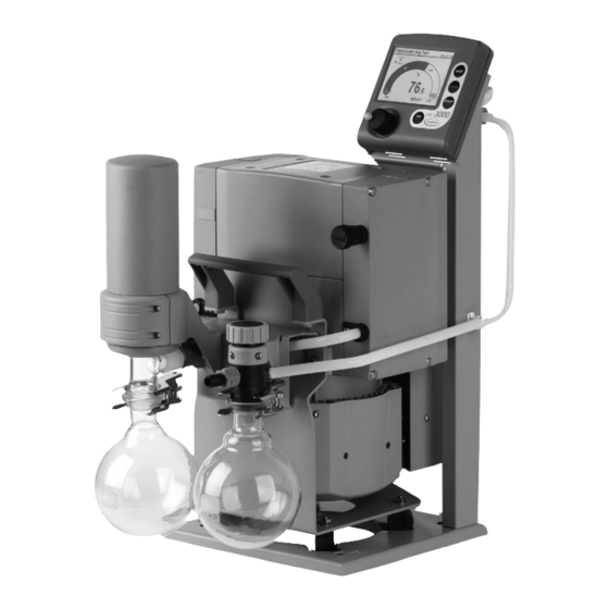
Page 15: Pump Parts
Fuse holder Collecting flask (outlet) ME 4C NT VARIO Documents are only to be used and distributed completely and unchanged. It is strictly the users’ responsibility to check carefully the validity of this document with respect to his product. Manual-no.: 999164 / 19/05/2009... - Page 16 page 16 of 75 MZ 2C NT VARIO MD 4C NT VARIO Documents are only to be used and distributed completely and unchanged. It is strictly the users’ responsibility to check carefully the validity of this document with respect to his product. Manual-no.: 999164 / 19/05/2009...
- Page 17 page 17 of 75 PC 3002 VARIO underside terminal box: PC 3003 VARIO / PC 3004 VARIO Documents are only to be used and distributed completely and unchanged. It is strictly the users’ responsibility to check carefully the validity of this document with respect to his product. Manual-no.: 999164 / 19/05/2009...
- Page 18 page 18 of 75 MV 10C VARIO-B / MD 12C VARIO-B outlet side MV 10C VARIO-B outlet side MD 12C VARIO-B PC 3010 VARIO / PC 3012 VARIO Documents are only to be used and distributed completely and unchanged. It is strictly the users’ responsibility to check carefully the validity of this document with respect to his product.
- Page 19 page 19 of 75 Rear side CVC 3000 Connection of the VACUU • BUS line to NT VARIO / VARIO-B pump venting connection bushes for connection of VACUU•BUS components (e.g. coolant valve) serial interface RS 232 C measurement stand foot, remov- connection able, also for mount- ing in a rod clamp...
-
Page 20: Use And Operation
Secure hose connections at the pump appropriately against accidental detaching. The VACUUBRAND controller CVC 3000 can only be operated with components compatible to the VACUUBRAND VACUU•BUS system, see accessories. The vacuum controller CVC 3000 controls VACUUBRAND diaphragm pumps NT VARIO and VARIO-B, pumping units PC 30xx VARIO and optional coolant and vent- ing valves. - Page 21 page 21 of 75 CVC 3000 The CVC 3000 is equipped with an internal capacitive pressure transducer with ce- ramic diaphragm to measure the actual pressure independently of the gas type and with reference to the vacuum, i. e. absolute. Pumps NT VARIO and VARIO-B: ☞...
- Page 22 page 22 of 75 Exhaust waste vapour condenser: PC 301x VARIO ➨ Assemble hose nozzles for coolant inlet and coolant outlet pipelines at the exhaust waste vapour condenser. The exhaust waste vapour condenser enables an efficient condensation of the pumped vapours at the outlet. ☞...
-
Page 23: Attention: Important Notes Regarding The Use Of Gas Ballast
page 23 of 75 If pumping condensable vapours (water vapour, solvents, ..), let the pump run with gas ballast to reduce condensation in the pump. Operation with silencer at the outlet: Operating the pump at high inlet pressure or pumping dusty gases for a long time may cause clogging of the silencer. Check the silencer regularly and replace if necessary. - Page 24 page 24 of 75 Attention: Notes concerning the operation of the exhaust waste vapour condenser ☞ The gas outlet (hose nozzle 10 mm) must not be blocked. The exhaust pipeline has always to be free and pressureless to enable an unhindered discharge of gases. ☞...
-
Page 25: Shutdown
page 25 of 75 Shutdown Short-term: NOTICE Has the pump been exposed to condensate? Allow the pump to continue to run at atmospheric pressure for a few minutes (continuous pumping). Has the pump been exposed to media which may damage the pump materials or forms deposits? Check and clean pump heads if necessary. -
Page 26: Vacuum Controller Cvc 3000
page 26 of 75 Vacuum Controller CVC 3000 When switching on the controller CVC 3000 for the very first time, a menu to select the language of the controller menu is displayed. Select the desired language e.g., ”English” by turning the selection knob and press to confirm. - Page 27 page 27 of 75 Display and symbols Function of the device: Vac control (displayed in the upper left corner) Pump down Vac control Auto mode (only with NT VARIO pump) Program VACUULAN Configuration 1013 . 2 1013.2 Actual absolute pressure at the pressure transducer mbar mbar...
- Page 28 page 28 of 75 Notes on selecting the function The controller CVC 3000 can be adapted to the specific application by choosing the appropriate function depending on the connected components and the requirements of the application. Automatic detection of the components When switching on the controller the actual configuration of the connected components is checked automatically.
-
Page 29: Menu Guide
page 29 of 75 Menu guide Vac control Pump down Set vacuum 100 mbar Speed Speed Minimum Maximum Delay Delay Duration Duration - - - - - - Graphic - - - - - - - - - - - - Graphic - - - - - - - - - - - - - Back - - - - - - - - - - - - - - Back - - - - - - - Vac control... -
Page 30: Function Pump Down
page 30 of 75 Function Pump down ➨ Continuous pumping with pressure and time settings • Operation on demand of a speed controlled NT VARIO / VARIO-B pump Preselections ☞ Use the selection knob to select the parameters. All parameters can be altered even while operation control is running. - Page 31 page 31 of 75 Temporary switching from ”Pump down” to ”Vac control” or ”Auto mode” (only if control is run- ning): ☞ Press key ”MODE”. The controller switches to function ”Vac control”, the current vacuum is used as set value. ☞...
-
Page 32: Function Vac Control
page 32 of 75 Function Vac control ➨ Vacuum control to a preset vacuum value • Operation on demand of a speed controlled pump (NT VARIO / VARIO-B) Preselections ☞ Use the selection knob to select the parameters. All parameters can be altered even while operation control is running. - Page 33 page 33 of 75 Temporary switching from ”Vac control” to ”Auto mode” while process control is running: ☞ Press key MODE. The controller switches to ”Auto mode” and adapts the boiling pressure starting with the actual set value. The preset function of the controller does not change due to this switching. When pressing key ”STOP”...
-
Page 34: Function Auto Mode
page 34 of 75 Function Auto mode ➨ Control of a NT VARIO / VARIO-B pump in function auto mode: Automatic determination of the boiling vacuum and automatic adaptation of the boiling vacuum in case of changing process parameters. Preselections ☞... -
Page 35: Function Program
page 35 of 75 Function Program ➨ Ten programs with up to ten program steps with preset values for vacuum and time can be set and stored. ☞ Edit: Preset values for the process run can be edited: Time: Process runtime for each program step to reach a preset vacuum level or if setting ”Step” runtime after having achieved the vacuum level. -
Page 36: Example For Use
page 36 of 75 The last process (not in function VACUULAN) is stored in the temporary data memory as long as the controller stays switched on. This program can be transferred to a storage space and edited. Once the program is finished, the clock symbol starts to flash. Confirm the end of the program by press- ing START/STOP (clock symbol will disappear). -
Page 37: Function Vacuulan
37 of 75 Function VACUULAN ➨ Optimised vacuum control for vacuum networks (e.g. VACUUBRAND VACUU•LAN) • Operation on demand of a speed controlled pump (NT VARIO / VARIO-B) Preselections ☞ Use the selection knob to select the parameters. ☞ Set vacuum (lower switch-off value): If the pressure drops below the ”Set vacuum” a time-meter starts to run;... -
Page 38: Examples For Use
page 38 of 75 Examples for use Assembly of a vacuum system ☞ Assemble vacuum connection lines between vacuum pump, CVC 3000 and vacuum application. ☞ Assemble the vacuum connection line between the controller and the vacuum application, if the con- troller is not part of a pumping unit. -
Page 39: Vacuum For Distillation And Evaporation (E. G. Rotary Evaporator)
page 39 of 75 Vacuum for distillation and evaporation (e. g. rotary evaporator) Semi-automatic distillation and evaporation ☞ Select function ”Pump down”. ☞ Start process by pressing key ”START/STOP”. ☞ Observe process. As soon as evaporation starts, press key ”MODE” (switching to ”Vac control”). The vacuum level is kept constant (at the boiling pressure). -
Page 40: Function Configuration
page 40 of 75 Function Configuration In the menu ”Configuration” the device parameters are preselected. Preselections ☞ Use the selection knob to select the parameters. ☞ Adjustment: Adjustment of the pressure transducer under vacuum and/or at atmospheric pressure, see also section ”Readjustment of CVC 3000”. Adjustment at atmospheric pressure is carried out at an absolute pressure value between 1060 - 700 mbar and under vacuum at an absolute vacuum value between 0 - 20 mbar. -
Page 41: Readjustment Of Cvc 3000
page 41 of 75 Readjustment of CVC 3000 The vacuum gauge was adjusted using factory standards, which are traceable NOTICE through regular calibration in an accredited laboratory (German Calibration service) to the German national pressure standard. Depending on the process and/or ac- curacy requirements, check the adjustment and readjust if necessary. -
Page 42: Calibration In The Factory
The controller is fully operable via the serial interface. Measuring results, preselections and the status of the controller can be read at any time. Factory-set the read and write commands are completely compatible to the VACUUBRAND con- troller CVC 2000 (see section ”read and write commands CVC 2000”). An extended instruction set is available using the command ”CVC 3”... -
Page 43: Read Commands "Cvc 2000
page 43 of 75 Read commands ”CVC 2000” Operation Command Response Description current pressure IN_PV_1 XXXX mbar or unit according to preselections XXXX Torr or XXXX hPa current frequency IN_PV_2 XX.X Hz device set IN_CFG XXXXX preselections 0: remote operation off 1: remote operation on 0: no automatic switch off 1: automatic switch off... -
Page 44: Write Commands "Cvc 2000
page 44 of 75 Write commands ”CVC 2000” Operation Command Parameter Description function OUT_MODE 1: continuous pumping 2: vacuum control without automatic 3: vacuum control with automatic 30: sensitivity: low 31: sensitivity: normal (optional) 32: sensitivity: high set vacuum OUT_SP_1 XXXX unit according to preselection (0001 to 1060 mbar (hPa) or 0001 to 0795 Torr) -
Page 45: Read Commands "Cvc 3000
page 45 of 75 Read commands ”CVC 3000” Operation Command Response Description unit according to preselections current IN_PV_1 XXXX.X mbar/Torr/hPa pressure 1-100% or HI current speed IN_PV_2 XXX% process runtime time IN_PV_3 XX:XX h:m pressure of all connected sensors pressure IN_PV_X XXXX.X XXXX.X ...mbar operation time in days and hours... - Page 46 page 46 of 75 Read commands ”CVC 3000” Operation Command Response Description Status IN_STAT XXXXXX process control 0 control off 1 pump down/ determining boiling point 2 set vacuum reached/ boiling pressure found 3 current pressure below set vacuum/ automatic switch-off 0 VACUULAN 1 Pump down 2 Vac control...
- Page 47 page 47 of 75 Read commands ”CVC 3000” Operation Command Response Description IN_SP_1 XXXX mbar or set vacuum XXXX Torr or XXXX hPa IN_SP_2 XXX% maximum speed (100% = ”HI”) IN_SP_3 XXXX mbar or switching on pressure for VACUULAN or XXXX Torr or two point control XXXX hPa...
-
Page 48: Write Commands "Cvc 3000
page 48 of 75 Write commands ”CVC 3000” Operation Command Parameter Description function OUT_MODE 0: VACUULAN 1: Pump down Attention: If control is running 2: Vac control 30: sensitivity: low only switching from 1 to 2, 2 to 3 3: Auto mode 31: sensitivity: normal and 3 to 2 is possible with takeo- 4: Program... - Page 49 page 49 of 75 Write commands ”CVC 3000” Description Operation Command Parameter mode 1 started START 0 Stop and delete fault STOP 1 Stop 2 Stop with adopting the set vacuum REMOTE* 0 Remote off 1 Remote on ECHO** 0 Echo off 1 Echo on, write command with return value 2 CVC 2000 commands 3 CVC 3000 commands***...
-
Page 50: Cleaning The Pressure Transducer
Small flange KF DN 16, with hose - for installation at hose nozzle..........677058 Small flange KF DN 16, for assembly directly at the valve head ..........699918 (at inlet of ME 4C NT VARIO / MD 4C NT VARIO; at outlet of ME 4C NT VARIO / MZ 2C NT VARIO) Small flange KF DN 16, for assembly directly at the valve head ..........699919... - Page 51 Hose nozzle DN 6/10 mm, for inlet ....................636635 Elbow piece (90°) for PTFE tubing DN 10/8 mm for assembly at inlet ........637873 PTFE tubing DN 10/8 mm (sold by meter) ...................638644 Conversion of VACUUBRAND valves with diode plug to VACUUBRAND valves with VACUU•BUS plug: VACUUBRAND-valve with diode...
-
Page 52: Troubleshooting
page 52 of 75 Troubleshooting Fault Possible cause Remedy ❑ No display. ➨ ✔ Mains not plugged in? Plug in mains plug of NT VARIO / VARIO-B pump. ➨ ✔ Controller CVC 3000 or Switch on devices. pump NT VARIO / VARIO-B switched off? ➨... - Page 53 page 53 of 75 Fault Possible cause Remedy ❑ Warning triangle and ➨ ✔ NT VARIO / VARIO-B pump Remove VMS. Restart con- pump symbol are flash- and VMS** (Vacuum Manage- troller. ing, six blips*. ment System) connected? ➨ ✔ Fault at the NT VARIO / Check pump, restart control- VARIO-B pump?
- Page 54 page 54 of 75 Fault Possible cause Remedy ❑ Pump does not achieve ➨ ✔ Outgassing substances or Check process parameters. its ultimate vacuum or vapour generated in the proc- usual pumping speed. ess? ➨ ✔ Diaphragms or valves defec- Replace diaphragms and/or tive? valves.
-
Page 55: Replacing Diaphragms And Valves
NOTICE Before starting maintenance vent the pump and isolate it from the vacuum system. Set of seals for ME 4C NT VARIO ....................696864 Set of seals for MZ 2C NT VARIO / PC 3002 VARIO ..............696869 Set of seals for MD 4C NT VARIO / PC 3003/3004 VARIO ............696870 Set of seals for MV 10C VARIO-B / MD 12C VARIO-B / PC 301x VARIO .........696821... -
Page 56: Cleaning And Inspecting The Pump Heads (Pumps Nt Vario / Pc 300X Vario)
page 56 of 75 Cleaning and inspecting the pump heads (pumps NT VARIO / PC 300x VARIO) Tools required (metric): Torx screw driver TX20 Hex key size 5 Flat-bladed screw driver 2.5 mm Flat pliers Diaphragm key w/f 66 The replacement of the diaphragm and the replacement of the valves can be carried out separately. ☞... - Page 57 57 of 75 Fittings and tubing of the different pump models: ME 4C NT VARIO MZ 2C NT VARIO MD 4C NT VARIO PC 3002 VARIO Documents are only to be used and distributed completely and unchanged. It is strictly the users’ responsibility to check carefully...
- Page 58 page 58 of 75 PC 3003 VARIO PC 3004 VARIO PC 3002/3003/3004 VARIO: ➨ Remove catchpots at inlet and outlet (see ”Use and opera- tion”). PC 3002/3003/3004 VARIO at inlet side: ➨ Open the hose clip at the inlet of the pumping unit (hose connection to controller CVC 3000) with a flat-bladed screw driver (see below).
-
Page 59: Replacing The Diaphragm
page 59 of 75 Opening the hose clip: ➨ Apply screw driver as shown and turn. ➨ Detach hose from hose clip at controller support. ➨ Use a Torx screw driver TX20 to unscrew the 4 screws fix- ating the head cover cowling. Pay attention to the washers under the screws and remove. -
Page 60: Replacing The Valves
page 60 of 75 ➨ Check for washers between the diaphragm support disc and the connecting rod. Do not mix the washers from the different pump heads. Make sure that the original number is reassembled at the individual pump head. ☞... - Page 61 page 61 of 75 Loosen the clamping brackets on the valve heads. ➨ Unscrew at each clamping bracket the two countersunk screws with a Torx screw driver TX20. Remove the clamp- ing brackets. ➨ Remove valve heads conjointly with disc springs, con- nection tube if applicable, hose nozzles and connection fasteners or move the valve heads carefully aside.
- Page 62 page 62 of 75 ➨ Bring the diaphragms into a position in which they are in contact with the housing and centred with respect to the bore. ➨ Put on head cover with valve heads and connections. ☞ Pay attention to the correct orientation of the head covers: Housing with cylinder pin: The cylinder pin at the pump housing has to fit into the recess at the head cover.
-
Page 63: Cleaning And Inspecting The Pump Heads (Pumps Vario-B / Pc 301X Vario)
page 63 of 75 PC 3002/3003/3004 VARIO: ➨ Assemble catchpots with joint clips. Cleaning and inspecting the pump heads (pumps VARIO-B / PC 301x VARIO) Tools: - Phillips screw driver size 2 - Open-ended wrench w/f 10/14/16/17 - Hex key size 5 - Diaphragm key w/f 66 Disassembling the pump from the pumping unit (PC 3010/3012 VARIO) •... - Page 64 page 64 of 75 ➨ Turn the fittings with an open-ended wrench (w/f 14, at outlet w/f 16) to detach the hoses from the pump heads. ☞ Do not remove the elbow fittings from the pump heads. Through reassembly a leak may result. View of the disassembled pump head parts Pump head parts: 1: Housing cover with housing...
- Page 65 page 65 of 75 Inlet side Pumps VARIO-B / Pumping units PC 301x VARIO Outlet side MV 10C VARIO-B / PC 3010 VARIO MD 12C VARIO-B / PC 3012 VARIO ➨ To check the valves and the diaphragms use a hex key to remove four socket-head screws from the pump head and remove the upper part of the housing (housing cover with housing cover insert) together with the head cover,...
-
Page 66: Replacing The Diaphragm
page 66 of 75 Replacing the diaphragm ☞ Check diaphragm for damage and replace if necessary. ➨ Lift diaphragm carefully sidewise. ☞ Never use a spiky or sharp-edged tool to lift the dia- phragm. ➨ Use the diaphragm key to grip the diaphragm support disc below the diaphragm. -
Page 67: Assembling The Pump Heads
page 67 of 75 Assembling the pump heads ➨ Bring connecting rod into a position in which the diaphragm is in contact with the housing and centred with respect to the bore. Reassemble in reverse order. ➨ Install head cover with O-rings, valves and housing cover with housing cover insert. -
Page 68: Replacing The Valve At The Distributor (Outlet Side)
page 68 of 75 Replacing the valve at the distributor (outlet side) ➨ Use open-ended wrench (w/f 17) to loosen the union nut of the hose, which runs directly to the cover plate of the distributor, at the pump head. ➨... - Page 69 page 69 of 75 Reassembling the pump at the pumping units PC 3010/3012 VARIO: ➨ Lay the pump on its side: the rating plate of the pump has to be on top (support pump suitably). ☞ Note that to install the console, the exhaust waste vapour condenser and the condensate flask must be on top.
-
Page 70: Replacing The Device Fuse
page 70 of 75 Replacing the device fuse fuse holder Pumps NT VARIO / PC 300x VARIO Pumps VARIO-B / PC 301x VARIO ➨ Unscrew the fuse holder using a screw driver. ➨ Replace the defective fuse by a fuse of the same type (see ”Technical data”) and reassemble holder with fuse to the pump. -
Page 71: Notes On Return To The Factory
page 71 of 75 Notes on return to the factory Repair - return - DKD calibration Safety and health of our staff, laws and regulations regarding the handling of dan- NOTICE gerous goods, occupational health and safety regulations and regulations regarding safe disposal of waste require that for all pumps and other products the “Health and safety clearance form“... -
Page 72: Health And Safety Clearance Form
-Technology for Vacuum Systems- Tel.: +49 9342 808-0 - Fax: +49 9342 808-450 © 2008 VACUUBRAND GMBH + CO KG Printed in Germany E-Mail: info@vacuubrand.de - Web: www.vacuubrand.de Documents are only to be used and distributed completely and unchanged. It is strictly the users’ responsibility to check carefully... - Page 73 Declaration of conformity Déclaration de conformité Pumpstand / Pumping unit / Groupe de pompage ME 4C NT VARIO (120V; 2613818), (230V; 2613819) MZ 2C NT VARIO (230V; 732400, 732401, 732402) MD 4C NT VARIO (230V; 736500, 736501, 736502) PC 3002 VARIO (230V; 733500, 733501, 733502) PC 3003 VARIO (230V;...
- Page 74 (Dr. F. Gitmans) (Dr. J. Dirscherl) Geschäftsführer / Managing Director / Gérant Technischer Leiter / Technical Director / Directeur technique VACUUBRAND GMBH + CO KG Alfred-Zippe-Str. 4 - 97877 Wertheim -Vakuumtechnik im System- Tel.: +49 9342 808-0 - Fax: +49 9342 808-450 -Technology for Vacuum Systems- E-Mail: info@vacuubrand.de...
- Page 75 Tel.: +49 9342 808-0 - Fax: +49 9342 808-450 E-Mail: info@vacuubrand.de - Web: www.vacuubrand.de © 2009 VACUUBRAND GMBH + CO KG Printed in Germany Documents are only to be used and distributed completely and unchanged. It is strictly the users’ responsibility to check carefully...
Need help?
Do you have a question about the ME 4C NT VARIO and is the answer not in the manual?
Questions and answers