vacuubrand PC 3002 VARIO select Instructions For Use Manual
Chemistry pumping units
Hide thumbs
Also See for PC 3002 VARIO select:
- Instructions for use manual (129 pages) ,
- Instructions for use manual (88 pages)

Related Manuals for vacuubrand PC 3002 VARIO select


Summary of Contents for vacuubrand PC 3002 VARIO select
- Page 1 Technology for Vacuum Systems hemistry pumping units PC 3002 VARIO select PC 3003 VARIO select PC 3004 VARIO select PC 3004 VARIO select EKP Instructions for use Original instructions OI no.: 20901334...
- Page 2 +49 9342 808‑5550 ƒ Service +49 9342 808‑5660 Fax: +49 9342 808‑5555 E‑Mail: info@vacuubrand.com Web: www.vacuubrand.com Thank you for purchasing this product from VACUUBRAND GMBH + CO KG . You have chosen a modern and techni- cally high quality product. 20901334_EN_PC3000_VARIO_select_Serie_V1.0_050418...
-
Page 3: Table Of Contents
Content TABLE OF CONTENT Introduction User information ....... . . 5 1.2 About this document. - Page 4 Content 4.3 Connection ........33 4.3.1 Vacuum connection (IN) .
-
Page 5: Introduction
We reserve the right to make technical and design changes in ƒ the course of continuous product improvement. Copyright The content of this manual is protected by copyright. Only copies Copyright © for internal use are allowed, e. g., for professional training. © VACUUBRAND GMBH + CO KG 20901334_EN_PC3000_VARIO_select_Serie_V1.0_050418... -
Page 6: About This Document
If your manual is incomplete, you can request a replace‑ Contact us ƒ ment. Alternatively, you can use our download portal: www.vacuubrand.com You are welcome to contact us at any time in writing or by tele‑ ƒ phone if you would like more information, have questions about our products or wish to share feedback with us. -
Page 7: Display Conventions
Introduction 1.2.2 Display conventions Warning levels DANGER Display conventions Indicates an imminent hazardous situation. Disregarding the situation will result in serious and even fatal injury or death. Take appropriate action to avoid dangerous situation! > > WARNING Indicates a potentially hazardous situation. Disregarding the situation could result in serious, even fatal injury or massive damage to property. -
Page 8: Symbols And Icons
Introduction 1.2.3 Symbols and icons This manual uses symbols and icons. Safety symbols indicate specific risks associated with handling the product. Symbols and icons are designed to help you identify risks more easily. Safety symbols Explanation of Hazardous substance ‑ General safety symbols hazards to human health. -
Page 9: Handling Instructions (Action Steps)
Introduction 1.2.4 Handling instructions (action steps) Instructions (single step) Display of action steps > Perform the step described. 5 Result of action Instructions (multiple steps) 1. First step 2. Next step 5 Result of action Perform the steps in the order described. 1.2.5 Abbreviations abs. -
Page 10: Term Definitions
Peltronic Electronic cooler with Peltier elements mounted ® at the outlet; condenses solvent vapors without external coolant. VACUU·BUS Bus system from VACUUBRAND for com‑ ® munication between peripheral devices with VACUU·BUS enabled gauges and controllers. ® The maximum permissible cable length is 30 m. - Page 11 Introduction Product‑specific VARIO drive Speed control for vacuum pump; the motor ® terms runs only as fast as necessary to meet de‑ mand. * only suitable for condensation of vapors 20901334_EN_PC3000_VARIO_select_Serie_V1.0_050418...
-
Page 12: Safety Information
Safety information Safety information The information in this chapter must be observed by everyone who works with the product described here. The safety information is valid for the entire life cycle of the product. 2.1 Usage Only use the product if it is in perfect working condition. 2.1.1 Intended use A chemistry pumping unit of the PC 3000 VARIO select... -
Page 13: Improper Use
Safety information 2.1.2 Improper use Incorrect use or any application which does not correspond to the Improper use technical data may result in injury or damage to property. Improper use includes: using the product contrary to its intended use, ƒ operation at improper environmental and operating conditions, ƒ... -
Page 14: Obligations
Safety information 2.2 Obligations 2.2.1 Operator obligations The owner defines the responsibilities and ensures that only Operator obligations trained personnel or specialists work at the vacuum system. This applies in particular to connection, assembly and maintenance work and troubleshooting. Users in the areas of competence in the Responsibility matrix must possess the relevant qualifications for the activities listed. -
Page 15: Target Group Description
Assignment Matrix Installation Commissioning Network integration Operation Error report Remedy Maintenance Repair Repair order Cleaning, simple Empty separator flask Shutdown Decontamination see also website: VACUUBRAND > Support > Instructions for repair Alternatively, arrange for decontamination by a qualified service provider 20901334_EN_PC3000_VARIO_select_Serie_V1.0_050418... -
Page 16: General Safety Instructions
Safety information 2.4 General safety instructions Products from VACUUBRAND GMBH + CO KG are subject to Quality standards and safety stringent quality testing with regard to safety and operation. Prior to delivery each product has been tested thoroughly. 2.4.1 Protective clothing For operation no special protective clothing is required. -
Page 17: Laboratory And Working Materials
Safety information 2.4.3 Laboratory and working materials DANGER Hazardous substances could emit at the outlet. During aspiration, hazardous, toxic substances at the outlet can get into ambient air. Observe the national regulations for safe handling of > > hazardous substances. Please note that residual process media may pose a >... -
Page 18: Eliminate Sources Of Danger
Safety information 2.4.4 Eliminate sources of danger Take mechanical stability into account Due to the high compression ratio of the pump, pressure can de‑ Note mechanical load capacity velop at the outlet which exceeds that which the mechanical sta‑ bility of the system allows. >... - Page 19 Safety information Incorrect measurement due to an obstructed vacuum line, e.g., Avoid incorrect condensate in the vacuum line can distort the measurements of measurements the vacuum sensor. > Prevent overpressure > 1060 mbar (795 Torr) inside the suc‑ tion line. Avoid foreign bodies inside the pump Particles, liquids and dusts should not get inside the vacuum pump.
- Page 20 Safety information Risk of burns due to hot surface The surface of the vacuum pump can reach operating tempera‑ Surface tempera‑ tures tures higher than > 70 °C, in particualar when pumping heated media. > Avoid direct contact with the surface. >...
-
Page 21: Motor Protection
Safety information Keep signs legible Keep labels and information symbols and warning labels always Warning signs and labels in a well readable condition: > Connection labeling > Warning signs and notice labels > Motor data and rating plates 2.5 Motor protection The pump motor has a temperature sensor on the circuit board as Overheating protection, deadlock... -
Page 22: Atex Equipment Category
> If necessary vent with inert gas. Information on the ATEX equipment category is also available on our website at: www.vacuubrand.com/.../Information‑ATEX 20901334_EN_PC3000_VARIO_select_Serie_V1.0_050418... -
Page 23: Proper Disposal
Safety information 2.7 Proper disposal NOTICE Risk of environmental damage due to incorrect disposal of the product. Do not dispose your product in household waste! > > Electronic components are subject to hazardous waste treat‑ ment and must only be disposed of by certified specialists. Observe the national regulations for safe disposal and envi‑... -
Page 24: Product Description
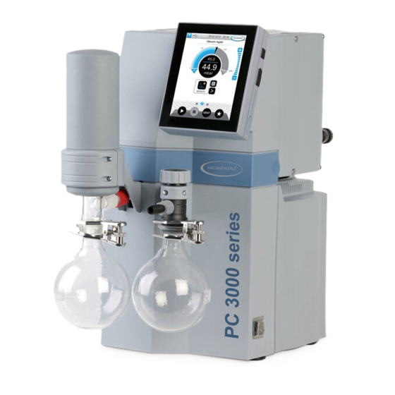
Product description Product description Pumping units of the PC 3000 VARIO select series generally consist in each case of a diaphragm pump with VARIO drive, ® a VACUU·SELECT vacuum controller as well as a cooler with ® separator. Chiller are available in various designs. The differences concern the functioning of the cooler. -
Page 25: Chemistry Pumping Units
Overview Chemistry pumping units Meaning Chemistry pumping unit Pump head AK EK ● ● a PC 3002 VARIO select b PC 3003 VARIO select ● ● c PC 3004 VARIO select ● ● ● ● d PC 3004 VARIO select EKP... -
Page 26: Condensers And Coolers
Product description 3.3 Condensers and coolers 3.3.1 Separator / Condenser at the inlet Connection to separator flask Connections at the Meaning Inlet connection vacuum IN 3.3.2 Condenser at the outlet Connection and coolant at vapor condenser Connections at the 10.1 10.2 Meaning Outlet connection EX... - Page 27 Product description Connections on the Peltronic emission condenser ® Connections at the Meaning Outlet connection EX Vacuum pump connection VACUU·BUS connection ® To switch the gauge on/off with tools, For detailed information on and descriptions of the Peltronic ® emission condenser, see manual #20901074.
-
Page 28: Examples Of Use
Product description 3.4 Examples of use Local vacuum network Example Local vacuum network Meaning Example of use: VACUU·LAN , network arrangement ® Vacuum hose* Laboratory furniture Exhaust gas hose (layed into a fume hood) Vacuum pumping unit PC 3004 VARIO select * pemanent installed PTFE-tubings 20901334_EN_PC3000_VARIO_select_Serie_V1.0_050418... - Page 29 Product description Vacuum drying Example Vacuum drying Chiller Meaning Coolant hoses Exhaust gas hose (layed into a fume hood) Vacuum pumping unit PC 3002 VARIO select Vacuum hose Example of use: Dryer cabinet 20901334_EN_PC3000_VARIO_select_Serie_V1.0_050418...
-
Page 30: Installation And Connection
Installation and connection Installation and connection 4.1 Transport Products from VACUUBRAND are packed in sturdy, recyclable packaging. The original packaging is accurately matched to your product for safe transport. If possible, please keep the original packaging, e. g., for >... -
Page 31: Installation
Installation and connection > Lift the device only using the recessed grips out of the packaging. 4.2 Installation NOTICE Condensate can damage the electronics. A large temperature difference between the storage location and the installation location can cause condensation. After goods receipt or storage, allow your vacuum device to >... - Page 32 Installation and connection Example 5 cm Sketch Minimum distances in laboratory furniture 5 cm 5 cm > When installing in laboratory furnishings, maintain a mini‑ IMPORTANT! mum distance of 5 cm (2 in.) from adjacent objects or sur‑ faces. >...
-
Page 33: Connection
Installation and connection 4.3 Connection All condensers of the pumping unit series have a vacuum connec‑ tion and an exhaust gas connection. Perform the connection for your pumping unit as described in the examples below. 4.3.1 Vacuum connection (IN) CAUTION Flexible vacuum hoses can contract during evacuation. - Page 34 Installation and connection Connect vacuum hose Example Vacuum connection at the inlet IN (a) (b) 1. Connect the sealing ring (a), knurled nut (b) and hose noz‑ zle (c) as shown. 2. Push the vacuum hose (d) from the apparatus onto the hose nozzle and fix it, e.
-
Page 35: Exhaust Gas Connection (Ex)
Installation and connection 4.3.2 Exhaust gas connection (EX) WARNING Risk of bursting due to overpressure inside the exhaust tube. Inadmissibly high pressure in the exhaust gas line can cause the vacuum pump to burst or damage seals. The exhaust gas line (outlet, gas outlet) must always >... -
Page 36: Kühlmittelanschluss Am Kondensator
Installation and connection 4.3.3 Kühlmittelanschluss am Kondensator An emission condenser EK has a connection for coolant liquids. Coolant connection Water or the liquid from, e. g., a chiller are suitable for cooling. IN = Feed line EX = outlet In a closed, in‑house cooling water circuit, the pressure should IMPORTANT! be limited to 3 bar (44 psi). -
Page 37: Venting Connection
Installation and connection 4.3.4 Venting connection DANGER Risk of explosion due to venting with air. Depending on the application, venting can cause explo‑ sive mixtures to form or other hazardous situations to arise. Never vent processes with air which could form an >... - Page 38 Installation and connection Venting with inert gas – connect venting valve Required connection material: Hose for hose nozzle (Ø 4 mm), e. g., silicone hose 4/6 mm. Connection to VENT port 1. Push the hose (b) into the VENT port (a) and fix the tube with the knurled nut 2.
-
Page 39: Gas Ballast (Gb)
Installation and connection 4.3.5 Gas ballast (GB) Use ambient air as gas ballast Example Position of gas ballast valve If ambient air is to be used as gas ballast, nothing must be con‑ nected at the pumping unit; gas ballast valve (c) see also chap- 5.2.2 Operation with gas ballast on page 45 Use inert gas as gas ballast –... -
Page 40: Electrical Connection
Installation and connection 4.3.6 Electrical connection Connect pumping unit electrically Example Electrical connection pumping unit 1. Insert the connector (s) of the power cable in the power con‑ nection of the vacuum pump. 2. Plug the wall power supply (t) into the mains socket. 5 Pumping unit connected electrically. - Page 41 Installation and connection IMPORTANT! > Use the power plug which fits your power supply. > Do not use multi‑outlet power strips connected in series as the power connection. 20901334_EN_PC3000_VARIO_select_Serie_V1.0_050418...
-
Page 42: Commissioning (Operation)
Commissioning (operation) Commissioning (operation) 5.1 Switch on Switch on pumping unit Switch on pumping unit 1. Switch the rocker switch (a) on – switch position I. 2. Press ON/OFF button (b) at the controller. 5 Display with start screen. 5 After approx. 30 seconds, the process screen appears with the operating elements in the controller display. - Page 43 Commissioning (operation) Process screen Process screen vacuum controller Status bar Analogue pressure reading – pressure curve Digital pressure reading – pressure value (target value, actual value, pressure unit) Process screen with context functions Screen navigation Operating elements for control Operating elements Button Operating elements Function...
-
Page 44: Operation ( See Description Of Controller)
Commissioning (operation) 5.2.1 Operation ( see description of controller) Start the vacuum controller Start Stop the vacuum controller Stop Venting Venting 20901334_EN_PC3000_VARIO_select_Serie_V1.0_050418... -
Page 45: Operation With Gas Ballast
Commissioning (operation) 5.2.2 Operation with gas ballast Meaning The provision of gas ballast (= addition of gas) ensures that vapors do not condense inside the vacuum pump but are instead ejected from the pump. This makes it possible to pump larger amounts of condensable vapors and service lives are prolonged. -
Page 46: Decommissioning (Switch Off)
Commissioning (operation) 5.3 Decommissioning (switch off) Take pumping unit out of operation 1. Stop the process and allow the pumping unit to run for Switch‑off pumping approx. 30 minutes, with open gas ballast or open inlet (IN). unit 5 Condensate and residual media are rinsed from the vacu‑ um pump. -
Page 47: Storage
Commissioning (operation) 5.4 Storage Store pumping unit 1. Clean the vacuum pumping unit when it is polluted. 2. Recommendation: Perform a preventive maintainance before storing the pumping unit. Especially if it ran more than 15000 operating hours 3. Close the suction and exhaust connections, e. g., with protec‑ tion caps. -
Page 48: Troubleshooting
VACUU·BUS plug‑in and cables to the measured val‑ connection or cables controller. defective or not con‑ nected. Specialist Defective sensor. Replace defective parts. 1 -> Phone: +49 9342 808-5660, fax: +49 9342 808-5555, service@vacuubrand. 20901334_EN_PC3000_VARIO_select_Serie_V1.0_050418... - Page 49 Troubleshooting Error ` Possible cause 3Remedy Personnel Specialist Venting valve No voltage applied. Check VACUU·BUS plug connection and does not oper‑ VACUU·BUS plug cables to the con‑ connection or cables troller. defective or not con‑ nected. Clean venting valve. Venting valve pol‑ If necessary, use luted.
- Page 50 Troubleshooting Error ` Possible cause 3Remedy Personnel resp. Spe- Vacuum line too long Shorten the dis‑ cialist or diameter too small. tance if possible and use vacuum lines with a larger cross‑section. Operator Condensate inside Allow vacuum pump the vacuum pump. to run for a few min‑...
- Page 51 Troubleshooting Error ` Possible cause 3Remedy Personnel Specialist Loud operating Ball bearing defec‑ Maintain vacuum tive. pump and replace noises defective parts or Outlet pipe open. send in the com‑ Glass flask on EK plete device. missing. Check exhaust gas line connections.
-
Page 52: Cleaning And Maintenance
Cleaning and maintenance Cleaning and maintenance WARNING Danger due to electrical voltage. Switch the device off before cleaning or performing > > maintenance on the device. Pull out power plug. > > Risk of injury because of toxic contaminated parts. Pumping hazardous media can result in hazardous substances adhering to parts on the inside of the pump. -
Page 53: Information On Service Work
Cleaning and maintenance 7.1 Information on service work Recommended maintenance intervals Maintenance intervals* if required 15000 h Replace diaphragms Replace valves Replace O‑ring Clean or replace molded PTFE‑hose Replace overpressure relief valve at EK Cleaning Pumping unit * Recommended maintenance interval after hours of operation and under normal operating conditions;... - Page 54 Cleaning and maintenance Tools needed for maintenance Example Tools N° Tool Size Service kit Service kit MZ2C NT VARIO #20696869 Service kit MD4C NT VARIO #20696870 Diaphragm wrench #20636554 SW66 Flat nose pliers Close hose clamps Flat‑head screwdriver Open hose clamps Gr.
-
Page 55: Cleaning
Cleaning and maintenance 7.2 Cleaning This chapter does not contain descriptions for the decontami‑ IMPORTANT! nation of the product. This chapter describes simple cleaning and care measures. > Before cleaning, switch off the Pumping unit. 7.2.1 Housing surface Clean surface Clean polluted surface with a clean, slightly moistened cloth. -
Page 56: Clean Or Replace Molded Ptfe-Hose
Cleaning and maintenance 7.2.3 Clean or replace molded PTFE‑hose Maintenance provides the opportunity to check the components of the Pumping unit, including the tubing. > Clean the inside of heavily polluted molded hoses, e. g., using a pipe cleaner or the like. >... -
Page 57: Vacuum Pump Maintenance
Cleaning and maintenance 7.3 Vacuum pump maintenance 7.3.1 Maintenance items Items to be maintained Example Maintenance of the pump heads A = 4‑headed B = 2‑headed Maintenance items Housing cover, power connection side Housing cover > Perform maintenance of the pump heads one after the other IMPORTANT! >... - Page 58 Cleaning and maintenance Exploded‑drawing pump head (example) Example Exploded‑drawing pump head PC 3004 Valve maintenance Clamping bracket + screw connections Disc spring Valve terminals Valves O‑rings size 26 x 2 Diaphragm maintenance Head cover + screw connections Diaphragm clamping disc with square‑head screw Diaphragm Diaphragm support disc Spacer discs, max.
-
Page 59: Change Diaphragms And Valves
Cleaning and maintenance 7.3.2 Change diaphragms and valves Preparation Example Prepare maintenance 1. Switch the Pumping unit off 2. Remove the glass flask from and disconnect the power the EK as well as the connect‑ plug. ed hoses. Example Disassemble EK 3. - Page 60 Cleaning and maintenance Example Disassemble EK 5. Unscrew the knurled nuts, 6. Set the cooler down securely remove the molded hose, and so that no liquid can escape. remove the cooler. Here you can check the over‑ pressure relief valve at EK and replace it if it is damaged.
- Page 61 Cleaning and maintenance Disassemble device and housing parts Example Disassemble housing parts on left 1. Unscrew the screw connec‑ 2. Remove the housing cover and tions from the housing cover; lay it aside. Torx screwdriver TX20 3. Open the hose clamps of the 4.
- Page 62 Cleaning and maintenance Replace diaphragms Example Diaphragm replacement 1. Press lightly on one of the dia‑ 2. Fold the diaphragm on the phragm clamping discs. sides upwards. 3. Carefully position the dia‑ 4. Lift the diaphragm with all parts phragm key on the diaphragm out of the vacuum pump.
- Page 63 Cleaning and maintenance Example Diaphragm replacement 5. Pull out the diaphragm clamp‑ 6. Position the new diaphragm on ing disc and remove the used the square of the diaphragm diaphragm. clamping disc. IMPORTANT! > Ensure that the diaphragm is inserted correctly, with the coated, light‑colored side facing up.
- Page 64 Cleaning and maintenance Example Diaphragm replacement 9. Hold the spacer discs firmly 10. Tighten the assembly hand‑ and place the assembly on the tight using the diaphragm rod thread. wrench. 11. Then position a torque 12. Repeat the process for the wrench with hexagon socket second diaphragm.
- Page 65 Cleaning and maintenance Replace valves Example Valve replacement 1. Take the pump head pair 2. Remove the gas ballast cap. which had been laid aside. Figure 2–4 optional description, since gas ballast mounted only on one side 3. Carefully pry off the cover. 4.
- Page 66 Cleaning and maintenance Example Valve replacement 7. Remove the valve terminals Top view: valve terminals, valves with the disc springs. and pump head pair. NOTICE Valves can adhere to the underside of a valve terminal. 8. Carefully remove the used 9.
- Page 67 Cleaning and maintenance Example Valve replacement 12. Position the new valves and Top view cutout: proper position‑ align them. ing of the valves. IN = Inlet (inlet) EX = Exhaust (outlet) 13. Place both valve terminals 14. Place the clamping brackets with the disc springs on the on the valve terminals and pump heads.
- Page 68 Cleaning and maintenance Assemble device and housing parts Before putting the pumping unit back into service, all device and housing parts which had been previously removed must be fixed once again. Example Assemble device and housing parts 1. Carefully press the diaphragms 2.
- Page 69 Cleaning and maintenance Example Assemble device and housing parts 5. Close the hose clamps on the 6. Put the housing cover on prop‑ hose nozzles, e. g., with a flat erly. nose pliers. 7. Screw in the screw connec‑ 8.
-
Page 70: Change Device Fuse
Cleaning and maintenance 7.3.3 Change device fuse At the power connection on the rear side of the pumping unit, there are 2 device fuses, type: 6,3 A/t – 5x20. Change device fuse 1. Pull out power plug. 2. Carefully pull out the fuse holder. -
Page 71: Appendix
Appendix Appendix 8.1 Technical information Chemistry pumping units PC 3002 VARIO select PC 3003 VARIO select PC 3004 VARIO select PC 3004 VARIO select EKP 8.1.1 Technical data Technical data Ambient conditions (US) Ambient temperature, max. 10–40 °C 50–104°F Operating temperature 10–40 °C... - Page 72 Appendix Electrical data (US) Technical data Nominal voltage 200‑230 VAC 100‑120 VAC Frequency 50 Hz 60 Hz Nominal current at 50 Hz ... PC 3002 1,4 A ... PC 3003 / PC 3004 2,5 A Capacity, max. 0,53 kW Device fuse 2x 6,3 A/t 5x20 Interface VACUU·BUS...
- Page 73 Appendix Weights* and dimensions (l x b x h) (US) PC 3002 VARIO select 419 mm x 243 mm 16.5 in x 9.57 in x 17.48 in x 444 mm Weight* 17,9 kg 39.5 lb PC 3003 VARIO select 419 mm x 270 mm 16.5 in x 10.63 in...
-
Page 74: Wetted Materials
Appendix 8.1.2 Wetted materials Component Wetted materials Wetted materials Pump Head cover ETFE, carbon‑fiber‑reinforced Diaphragm clamping disc ETFE, carbon‑fiber‑reinforced Diaphragm PTFE Valves FFPM O‑ring Valve terminal ETFE, carbon‑fiber‑reinforced Housing cover inside PTFE carbon‑fiber‑reinforced Silencer PBT, PVF Hose to silencer Hose fittings ETFE/ECTFE Pumping unit Inlet... -
Page 75: Rating Plate
Appendix 8.1.3 Rating plate Data on rating plate In the event of an error, make a note of the type and serial > > number on the rating plate. When contacting our Service Department, please provide > > the type and serial number from the rating plate. This will allow us to provide you with specific support and advice for your device. -
Page 76: Ordering Information
Appendix 8.2 Ordering information Chemistry pumping units Ordering information Order no. pumping unit series PC 3002 VARIO select 207335xx PC 3003 VARIO select 207385xx PC 3004 VARIO select 207375xx PC 3004 VARIO select EKP 207375xx * Order no. depends on power cable CEE, CH, UK, US, CN, IN Accessories Order no. - Page 77 Chemistry pumping units. Sources of supply Purchase original accessories and original spare parts from a International sales offices and subsidiary of VACUUBRAND GMBH + CO KG or your local distribution distributor. Information about our complete product range is available > >...
-
Page 78: Service
8.3 Service Take advantage of the comprehensive range of services avail‑ Service offer and able from service range VACUUBRAND GMBH + CO KG. Services in detail Product consultation and practical solutions ƒ Fast delivery of spare parts and accessories ƒ... -
Page 79: Index
Appendix 8.4 Index Index Instruction modules ....6 Abbreviations ....9, 10 Intended use . - Page 80 Appendix Index Responsibility matrix and areas of com‑ petence ..... . 15 Return (reshipment) ... . . 78 Return to service after maintenance 69 Risks of Venting .
-
Page 81: Ec Declaration Of Conformity
Chemie‑Pumpstand‑Serie / Chemistry pumping unit series / Groupe de pompage chimie Typ / Type / Type: PC 3002 VARIO select, PC 3003 VARIO select, PC 3004 VARIO select, PC 3004 EKP VARIO select Artikelnummer / Order number / Numéro d‘article: 20733554, 20738454, 20737554, 20737574 Seriennummer / Serial number / Numéro de série: Siehe Typenschild / See rating... -
Page 82: En_Pc3000_Vario_Select_Serie_V1.0
20901334_EN_PC3000_VARIO_select_Serie_V1.0_050418... - Page 83 20901334_EN_PC3000_VARIO_select_Serie_V1.0_050418...
- Page 84 Technology for Vacuum Systems Manufacturer: VACUUBRAND GMBH + CO KG Alfred‑Zippe‑Str. 4 97877 Wertheim GERMANY Phone: ƒ Head office +49 9342 808‑0 ƒ Sales +49 9342 808‑5550 ƒ Service +49 9342 808‑5660 Fax: +49 9342 808‑5555 E‑Mail: info@vacuubrand.com Web: www.vacuubrand.com...
Need help?
Do you have a question about the PC 3002 VARIO select and is the answer not in the manual?
Questions and answers