
Subscribe to Our Youtube Channel
Related Manuals for vacuubrand PC 3001 basic


Summary of Contents for vacuubrand PC 3001 basic
- Page 1 1 of 56 Technology for Vacuum Systems Instructions for use PC 3001 basic Chemistry pumping unit with speed control...
- Page 2 VACUU•LAN (US-Reg.No 3,704,401), VACUU•BUS , VACUU•CONTROL ® ® ® Peltronic , VARIO (US-Reg.No 3,833,788), VACUUBRAND (US-Reg.No ® ® ® 3,733,388) and also the shown company logos are registered trademarks of VACUUBRAND GMBH + CO KG in Germany and/or other countries.
- Page 3 page 3 of 56 Achtung: Die vorliegende Betriebsanleitung ist nicht in allen EU-Sprachen verfügbar. Der Anwender darf die beschriebenen Geräte nur dann in Betrieb nehmen, wenn er die vorliegende Anleitung versteht oder eine fachlich korrekte Übersetzung der voll- ständigen Anleitung vorliegen hat. Die Betriebsanleitung muss vor Inbetriebnahme der Geräte vollständig gelesen und verstanden werden, und alle geforderten Maß- nahmen müssen eingehalten werden.
- Page 4 page 4 of 56 Bemærk: Denne manual foreligger ikke på alle EU sprog. Brugeren må ikke be- tjene apparatet hvis manualen ikke er forstået. I det tilfælde skal en teknisk korrekt oversættelse af hele manual stilles til rådighed. Manual skal være gennemlæst og forstået før apparatet betjenes og alle nødvendige forholdsregler skal tages.
- Page 5 page 5 of 56 Figyelem! Ez a kezelési utasítás nem áll rendelkezésre az EU összes nyelvén. Ha a felhasználó nem érti jelen használati utasítás szövegét, nem üzemeltetheti a készüléket. Ez esetben a teljes gépkönyv fordításáról gondoskodni kell. Üzembe helyezés előtt a kezelőnek végig kell olvasnia, meg kell értenie azt, továbbá az üzemeltetéshez szükséges összes mérést el kell végeznie.
- Page 6 page 6 of 56 Attentie: Deze gebruiksaanwijzing is niet in alle talen van de EU verkrijgbaar. De gebruiker moet niet met dit apparaat gaan werken als voor hem/haar de gebruiks- aanwijzing niet voldoende duidelijk is. Bij gebruik van deze apparatuur is het nood- zakelijk een technisch correcte vertaling van de complete gebruiksaanwijzing te hebben.
- Page 7 page 7 of 56 Varning: Denna instruktion är inte tillgänglig på alla språk inom EU. Användaren får inte starta utrustningen om hon/han inte förstår denna instruktion. Om så är fallet måste en tekniskt korrekt instruktion göras tillgänglig. Instruktionen måste läsas och förstås helt före utrustningen tas i drift och nödvändiga åtgärder göres.
-
Page 8: Table Of Contents
Gas inlet temperatures ..............24 Wetted parts ..................25 Abbreviations ..................25 Pump parts ..................26 Upgrade kits for PC 3001 basic............27 Use and operation ............28 Installing a pump in a vacuum system ..........28 During operation ................30 Important notes regarding the use of gas ballast ...... -
Page 9: Safety Information
Make operating personnel aware of dangers arising from the pump and the pumped substances. VACUUBRAND disclaims any liability for inappropri- ate use of these pumps and for damage from failure to follow instructions contained in this manual. - Page 10 page 10 of 56 ➨ DANGER indicates a hazardous situation which, if not avoided, will result in death or serious injury. + WARNING indicates a hazardous situation which, if not avoided, could result in death or serious injury. • CAUTION indicates a hazardous situation which, if not avoided, could result in minor or moderate injury.
-
Page 11: General Information
page 11 of 56 General information Remove all packing material from the packing box. Re- NOTICE move the product from its packing-box and retain all pack- aging until the equipment is inspected and tested. Re- move the protective caps from the inlet and outlet ports and retain for future use. -
Page 12: Setting Up And Installing The Equipment
page 12 of 56 + Comply with all notes on correct vacuum and electri- cal connections; see section „Use and operation“, pg. + Do not use the pump to generate pressure. + The pumps are designed for ambient temperatures during operation between +50°F and +104°F (+10°C and +40°C). - Page 13 page 13 of 56 The supply cable may be fitted with a molded Europe- an IEC plug or a plug suitable for your local electrical supply. The cable contains wires color coded as fol- lows: green or green and yellow: ground; blue or white: neutral;...
-
Page 14: Ambient Conditions
page 14 of 56 • Check the power source and the pump’s rating plate to be sure that the power source and the equipment match in voltage, phase, and frequency. Make sure ventilation is adequate to maintain recommend- NOTICE ed operating temperature. Keep a minimum distance of 2 in (5 cm) between the cooling fan and surrounding items (e.g., housing, walls, etc.), or else install an external auto- matic ventilation system. -
Page 15: Operating Conditions
page 15 of 56 + Do not use this product in an area where it can fall or be pulled into water or other liquids. • Adopt suitable measures in case of differences from recommended conditions, e.g., using the equipment outdoors, installation in higher altitudes, conductive pollution or external condensation on the pump. - Page 16 page 16 of 56 ➨ The pumps are not suitable to pump any of the sub- stances listed below. Do not pump: - unstable substances - substances which react explosively under impact (mechanical stress) without air - substances which react explosively when being ex- posed to elevated temperatures without air, - substances subject to auto-ignition, - substances which are inflammable without air...
-
Page 17: Safety During Operation
page 17 of 56 Safety during operation ➨ Adopt suitable measures to prevent the release of dan- gerous, toxic, explosive, corrosive, noxious or pollut- ing fluids, vapors and gases. To prevent any emission of such substances from the pump outlet, install an appropriate collecting and disposal system and take protective action for pump and environment. - Page 18 page 18 of 56 + Interruption of the pump (e.g., due to power failure), failure of connected components or of parts of the sup- ply, or change in parameters must not be allowed to lead to dangerous conditions. In case of a diaphragm failure or in case of a leak in the manifold, pumped substances might be released into the environment or into the pump housing or motor.
-
Page 19: Maintenance And Repair
For details and for the online ”Instructions for repair” man- ual see www.vacuubrand.com. In normal use, the lifetime of the diaphragms and valves is typically 15,000 operating hours. Bearings have a typical durability of 40000 h. - Page 20 page 20 of 56 ➨ Note: The pump may be contaminated with process chemicals, which have been pumped during operation. Ensure that the pump is completely decontaminated before maintenance commences. + Take adequate precautions to protect people from the effects of dangerous substances if contamination has occurred.
-
Page 21: Important Information: Equipment Marking (Atex)
The overall category of the equipment depends on the connected com- ponents. If the connected components do not comply with the classifi- cation of the VACUUBRAND equipment, the specified category of the VACUUBRAND equipment is no longer valid. Vacuum pumps and vacuum gauges in category 3 are intended for con- nection to equipment in which during normal operation explosive atmo- spheres caused by gases, vapors or mists normally don’t occur;... - Page 22 page 22 of 56 • The equipment is designated for an ambient and gas inlet temperature during operation of +10 to +40°C. Never exceed these ambient and gas inlet temperatures. If pumping / measuring gases which are not potentially explosive, extended gas inlet temperatures are permissible. See instructions for use, section “Gas inlet temperatures”...
-
Page 23: Technical Data
23 of 56 Technical data Type PC 3001 basic Maximum pumping speed (ISO 21360) (2.0) Ultimate vacuum (absolute) Torr without gas ballast (mbar) Ultimate vacuum (absolute) Torr with gas ballast (mbar) Maximum permissible inlet and outlet pressure (absolute) (bar) (1.1) -
Page 24: Gas Inlet Temperatures
24 of 56 Type PC 3001 basic hose nozzle for tubing I.D. Inlet 1/4” / 3/8” (hose nozzle DN 6/10 mm) hose nozzle for tubing I.D. 3/8” Outlet (hose nozzle DN 10 mm) / silencer A-weighted emission sound pressure... -
Page 25: Wetted Parts
page 25 of 56 Wetted parts Components Wetted materials Pump Housing cover PTFE Head cover ETFE carbon fiber reinforced Diaphragm clamping disc ETFE carbon fiber reinforced Diaphragm PTFE Valve FFKM Pumping unit Inlet pumping unit PTFE (hose nozzle) Outlet pumping unit PVC / PP (silencer) Tubing PTFE... -
Page 26: Pump Parts
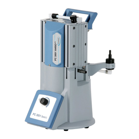
26 of 56 Pump parts Position Component Position Component MD 1C VARIO chemistry Inlet diaphragm pump Outlet (supplementary: Selection knob for motor with silencer) speed Gas ballast valve Mains connection Handle ON/OFF switch PC 3001 basic... -
Page 27: Upgrade Kits For Pc 3001 Basic
27 of 56 Upgrade kits for PC 3001 basic Upgrade kit CVC 3000 with inlet separator ..........20699921 Upgrade kit emission condenser ...............20699922 PC 3001 basic with PC 3001 basic with upgrade upgrade kit CVC 3000 kit emission condenser with inlet separator... -
Page 28: Use And Operation
page 28 of 56 Use and operation Notes regarding the selection knob and the motor speed Turning the knob to the left decreases the motor speed, turning the knob to the right increases the motor speed. Pumping at high motor speed increases the pumping speed of the pump. - Page 29 page 29 of 56 + Make sure ventilation is adequate, especially if the pump is installed in an enclosure, or if the ambient tempera- ture is elevated. Provide external ventilation, if neces- sary. • Reduce the transmission of vibration. Prevent mechan- ical load due to rigid pipelines.
-
Page 30: During Operation
page 30 of 56 as short as possible to avoid flow losses. Locate the pump as closely as possible to the application. Always install outlet tubing descending from the pump or provide other measures to avoid backflow of condensate towards the pump. When assembling, ensure vacuum-tightness. - Page 31 page 31 of 56 pressure at outlet and the maximum pressure dif- ference between inlet and outlet ports. Do not start the pump if the pressure difference between NOTICE inlet and outlet ports exceeds max. 16.0 psi (1.1 bar). Attempts to start the pump at higher pressure difference may cause stalling and damage of the motor.
-
Page 32: Important Notes Regarding The Use Of Gas Ballast
page 32 of 56 last Gas ballast is a continuous purge to keep the pump’s in- terior as clean as possible and to reduce the possibility of condensation inside the pump. ➨ Air and pumped media might react inside the pump or at the outlet of the pump and form hazardous or explo- sive mixtures, when you use air rather than inert gas for the gas ballast. - Page 33 page 33 of 56 The pump can be switched off under vacuum. Short-term: NOTICE Has the pump been exposed to condensate? - Allow the pump to continue to run at atmospheric pres- sure for a few minutes. Has the pump been exposed to media which may damage the pump materials or form deposits? - Check and clean pump heads if necessary.
-
Page 34: Accessories
page 34 of 56 Accessories Upgrade kits: Upgrade kit CVC 3000 with inlet separator ..........20699921 Upgrade kit emission condenser ...............20699922 Accessories for vacuum controller CVC 3000: External pressure transducer VSK 3000 ...........20636657 capacitive, ceramic diaphragm sensor 1080-0.1 mbar Coolant valve VKW-B, 24 V= ..............20674220 Venting valve VBM-B / KF 16, 24 V= ............20674217 KF 16 / hose nozzle 6/10 mm, 24 V= VACUU•BUS Y-type adapter ..............20636656... -
Page 35: Troubleshooting
page 35 of 56 Troubleshooting Fault Possible cause Remedy ❑ Pump does not ➨ Electrical power cord ✔ Plug in power cord. start or stops im- not plugged in, electri- Check electrical supply mediately. cal supply failure? voltage. Check fuse. ➨... - Page 36 page 36 of 56 Fault Possible cause Remedy ❑ Pump does not ➨ Pump temperature too ✔ Ensure sufficient cooling achieve its ultimate high (motor speed re- of the pump or reduce vacuum or usual duced)? inlet pressure. pumping speed. ❑...
-
Page 37: Replacing Diaphragms And Valves
page 37 of 56 Replacing diaphragms and valves + Please read section ”Replacing diaphragms and valves” com- pletely before starting maintenance. The pictures may show other versions of pumps. This does not change the method of replacing diaphragms and valves. ➨... - Page 38 page 38 of 56 Ensure that maintenance is done only by suitably NOTICE trained and supervised technicians. The valves and diaphragms are wear parts. If the rated ultimate vacuum is no longer achieved or in case of in- creased noise level, the pump interior, the diaphragms and the valves must be cleaned and the diaphragms and valves must be checked for cracks or other damage.
-
Page 39: Cleaning And Inspecting The Pump Heads
page 39 of 56 Cleaning and inspecting the pump heads + Service only one side of the pump at a time to avoid the mixing of parts. ➨ Loosen the union nut (K) of the hose con- nection next to the gas ballast valve with an open-ended wrench (w/f 17). - Page 40 page 40 of 56 View of the disassembled pump head parts Pump head parts: A: Housing cover with insert G: Washer(s) B: Valves H: Connecting rod C: Head cover I: Housing D: Diaphragm clamping disc J: Housing bearing flange with square head screw K: Union nut E: Diaphragm L: Fitting...
-
Page 41: Replacing The Diaphragm
page 41 of 56 ➨ Remove the head cover (C) carefully from the housing cover (A). Note position and alignment of valves (B). Remove the valves. + Replace valves if necessary. + Use petroleum ether or other industrial sol- vent to remove deposits. Do not inhale va- pors. - Page 42 page 42 of 56 + If the old diaphragm is difficult to separate from the diaphragm support disc, immerse assembly in naphtha or petroleum ether. Do not inhale vapors! ➨ Position new diaphragm (E) between dia- phragm clamping disc with square head screw (D) and diaphragm support disc (F).
- Page 43 page 43 of 56 ➨ Put on head covers (C). + Pay attention to the correct orientation of the head covers (see figure below). + Make sure that the diaphragms stay cen- tered with respect to the bores so that they will become clamped uniformly between housing (I) and head covers (C).
-
Page 44: Assembling The Housing Cover At The Inlet Side
page 44 of 56 Assembling the housing cover at the inlet side ➨ Put on housing cover (A). + Move housing cover slightly to ensure that the head covers are cor- rectly positioned. ➨ Screw in the Allen head screws at the head cover in a diagonal pattern with a 4 mm wide Allen key, loosely at first, to align, then tighten. -
Page 45: Assembling The Housing Cover At The Side Of The On/Off Switch
page 45 of 56 + Never use a pointed or sharp-edged tool to remove parts (e.g., screw- driver). We recommend using a rubber mallet or compressed air (to be blown carefully into port). ➨ R aise the housing cover. ➨ P ull the tubing off the hose connector at the the housing cover. -
Page 46: Assembling The Fittings
page 46 of 56 ➨ Slip connection hose onto hose connector below the housing cover. ➨ Close hose clip with flat pliers. Assembling the fittings ➨ Attach the handle at the housing cover (use 5 mm wide Allen key) ➨ Slip the hose onto the hose connector by turning the fitting (L) with an open-ended wrench w/f 14. - Page 47 page 47 of 56 If the pump does not achieve the ultimate vacuum: - Whenever the diaphragms and valves have been replaced, a break-in period of several hours is required before the pump achieves its ulti- mate vacuum. - In case of an unusual noise, switch off pump immediately and check clamping disc positions.
-
Page 48: Repair - Maintenance - Return - Calibration
3 or 4. These devices cannot be checked, maintained or re- paired. Also decontaminated devices must not returned to VACUUBRAND due to a residual risk. The same conditions apply to on-site work. No repair, maintenance, return or calibration is possi- ble unless the correctly completed health and safety clearance form is returned. - Page 49 page 49 of 56 If you do not wish a repair on the basis of our quotation, the device may be returned to you disassembled and at your expense. In many cases, the components must be cleaned in the factory prior to repair. For cleaning we use an environmentally friendly water based process.
-
Page 50: Warranty
50 of 56 Warranty VACUUBRAND shall be liable for insuring that this prod- uct, including any agreed installation, has been free of de- fects at the time of the transfer of risk. VACUUBRAND shall not be liable for the consequences... -
Page 51: Health And Safety Clearance Form
* Contact the VACUUBRAND service absolutely before dispatching the device. ** Devices which have been in contact with biological substances of risk level 3 or 4 cannot be checked, main- tained or repaired. Also decontaminated devices must not returned to VACUUBRAND due to a residual risk. ☐... -
Page 52: Ec Declaration Of Conformity Of The Machinery
Bevollmächtigter für die Zusammenstellung der technischen Unterlagen / Person authorized to compile the technical file / Personne autorisée à constituer le dossier technique: Dr. F. Gitmans · VACUUBRAND GMBH + CO KG · Alfred-Zippe-Str. 4 · 97877 Wertheim · Germany Wertheim, 02.05.2019 . -
Page 53: China Rohs
China RoHS DECLARATION OF CONFORMITY – China RoHS 2 VACUUBRAND GMBH + CO KG has made reasonable efforts to ensure that hazardous mate- rials and substances may not be used in its products. In order to determine the concentration of hazardous substances in all homogeneous materials of the subassemblies, a “Product Conformity Assessment”... - Page 54 (Pb), mercury (Hg), cadmium (Cd), hexavalent chromium (Cr+VI), polybrominated biphenyls (PBB), and polybrominated diphenyl ethers (PBDE). Products manufactured by VACUUBRAND may enter into further devices (e.g., rotary evaporator) or can be used together with other appliances (e.g., usage as booster pumps).
- Page 55 page 55 of 56...
- Page 56 Alfred-Zippe-Str. 4 · 97877 Wertheim / Germany T +49 9342 808-0 · F +49 9342 808-5555 info@vacuubrand.com · www.vacuubrand.com VACUUBRAND GMBH + CO KG - Technology for Vacuum Systems - © 2019 VACUUBRAND GMBH + CO KG Printed in Germany Manual-no.: 20901238 / 05/02/2019...
Need help?
Do you have a question about the PC 3001 basic and is the answer not in the manual?
Questions and answers