
Related Manuals for vacuubrand PC301 VARIO select Series


Summary of Contents for vacuubrand PC301 VARIO select Series
- Page 1 Technology for vacuum systems Chemistry pumping unit series PC 3010 VARIO select PC 3016 VARIO select PC 3012 VARIO select PC 3012 VARIO select EKP Instructions for use Original instructions EN-US 20901118...
- Page 2 Sales: +49 9342 808-5550 Service: +49 9342 808-5660 Fax: +49 9342 808-5555 Email: info@vacuubrand.com Web: www.vacuubrand.com Thank you for purchasing this product from VACUUBRAND GMBH + CO KG. You have chosen a modern and techni- cally high quality product. 20901118_EN-US_PC301x VARIO select Serie_V1.3_100720...
-
Page 3: Table Of Contents
TABLE OF CONTENTS About this document 1.1 User information............. 5 1.2 Manual structure ............6 1.3 Display conventions ............7 1.4 Symbols and icons ............8 1.5 Instructions..............9 1.6 Abbreviations ..............10 1.7 Term definitions..............11 Safety information 2.1 Usage................12 2.1.1 Intended use ............12 2.1.2 Improper use............13 2.1.3 Foreseeable misuse ..........13 2.2 Obligations ..............14... - Page 4 4.4.3 Coolant connection at the condenser ....33 4.4.4 Venting connection ..........35 4.4.5 Gas ballast (GB) ............36 4.5 Electrical connection ............38 Commissioning (operation) 5.1 Switch on................40 5.2 Operation ...............41 5.2.1 User interface ............41 5.2.2 Operation ...............42 5.2.3 Operation with gas ballast ........43 5.3 Shutdown (switch off).............44 5.4 Storage................44 Troubleshooting...
-
Page 5: About This Document
PC 301x VARIO select chemistry pumping unit. Copyright © Copyright The content of this Instruction manual is protected by copyright. Only copies for internal use are allowed, e.g., for professional training. © VACUUBRAND GMBH + CO KG 20901118_EN-US_PC301x VARIO select Serie_V1.3_100720... -
Page 6: Manual Structure
If your Instruction manual is incomplete, you can request a replacement. Alternatively, you can use our download portal: www.vacuubrand.com You are welcome to contact us at any time in writing or by telephone if you would like more information, have questions about our products or wish to share feedback with us. -
Page 7: Display Conventions
About this document 1.3 Display conventions Warning levels Display of warning DANGER levels Warns of an imminent hazard. Disregarding the situation could result in extremely seri- ous injury or death. Take appropriate action to avoid dangerous situa- Ø tions! WARNING Warns of a potentially hazardous situation. -
Page 8: Symbols And Icons
About this document 1.4 Symbols and icons This manual uses symbols and icons. Safety symbols indicate specific risks associated with handling the product. Symbols and icons are designed to help you identify risks more easily. Safety symbols Explanation General danger sign. Danger: electricity. -
Page 9: Instructions
About this document 1.5 Instructions Instruction (single step) ð Perform the step described. Instructions Result of action Instruction (multiple steps) 1. First step 2. Next step Result of action Carry out instructions requiring multiple steps in the order de- scribed. Instruction (graphic description) -> Example Schematic diagram... -
Page 10: Abbreviations
About this document 1.6 Abbreviations Abbreviations used >/ not greater than abs. Absolute Separator flask Atmospheric pressure (bar graph, program) Interior diameter Nominal diameter Vapor condenser Peltronic® or EK¬ Peltronic® vapor condenser Outlet (exhaust, exit), exhaust gas connection ATEX equipment labeling Fluoroelastomer Gas ballast Size... -
Page 11: Term Definitions
Dry ice con- Cooling condenser mounted at the outlet (pressure denser side) with receiving flask and dry ice as coolant. ® VACUU·BUS Bus system from VACUUBRAND for communication ® of peripheral devices with VACUU·BUS -enabled gauges and controllers. ® ®... -
Page 12: Safety Information
Safety information Safety information The information in this chapter must be observed by everyone who works with the product described here. The safety information applies to the entire life cycle of the equipment. 2.1 Usage Only use the product if it is in perfect working condition. 2.1.1 Intended use Intended use A chemistry pumping unit of product series PC 301x VARIO se-... -
Page 13: Improper Use
Safety information 2.1.2 Improper use Improper use Incorrect use or any application which does not correspond to the technical data may result in injury or damage to property. Improper use includes: using the product contrary to its intended use, operation under inadmissible environmental and operating conditions, operation despite obvious errors or defective safety devices, unauthorized extensions or conversions, in particular when... -
Page 14: Obligations
Safety information 2.2 Obligations Operator obligations Operator obliga- The owner defines the responsibilities and ensures that only tions trained personnel or specialists work on the vacuum system. This applies in particular to connection, installation and mainte- nance work and troubleshooting. g ... -
Page 15: Target Group Description
Operation Error report Remedy Maintenance Repair Repair order Cleaning, simple Empty the separator Shutdown Decontamination 3 see also Homepage: VACUUBRAND > Support > Instructions for repair 4 Alternatively, arrange for decontamination by a qualified service provider. 20901118_EN-US_PC301x VARIO select Serie_V1.3_100720... -
Page 16: General Safety Information
Safety information 2.4 General safety information Quality standards Products from VACUUBRAND GMBH + CO KG are subject to and safety stringent quality testing with regard to safety and operation. Each product undergoes a comprehensive test program prior to delivery. Observe the instructions for all actions as specified in this man- ual. -
Page 17: Laboratory And Working Materials
Safety information 2.7 Laboratory and working materials DANGER Hazardous substances could be discharged at the outlet. During aspiration, hazardous, toxic substances at the outlet can get into the ambient air. Observe the relevant safety regulations for safe han- Ø dling of hazardous substances. Please note that residual process media may pose a Ø... -
Page 18: Possible Sources Of Danger
Safety information Prevent foreign bodies inside the pump Observe vacuum Particles, liquids and dust must not get inside the vacuum pump. pump design ð Do not pump any substances which could form deposits in- side the vacuum pump. ð Install suitable separators and/or filters upstream of the in- let. - Page 19 Safety information ð Incorrect measurements due to a blocked vacuum line, e.g., condensate in the vacuum line, can distort the measure- ments taken by the vacuum sensor. ð Avoid overpressure in the suction line (>/ 1060 mbar [>/ 795 Torr]). Hazards during venting Observe hazards Depending on the application, explosive mixtures can form or during venting other hazardous situations can arise in systems.
-
Page 20: Motor Protection
Safety information ð Place the device on a stable surface. A soft surface such as a foam rubber sound absorber can impair and block the air supply. ð Clean polluted ventilation slots. ð Remove the cover used as transport protection from the de- vice before operating it. -
Page 21: Disposal
Safety information ATEX equipment labeling ATEX equipment Vacuum equipment labeled with has ATEX approval in line category with the ATEX marking on the rating plate. Operation is only permitted when in perfect working condition. The product is designed for a low level of mechanical stress and must be installed in such a way that it cannot sustain mechani- cal damage from outside. -
Page 22: Product Description
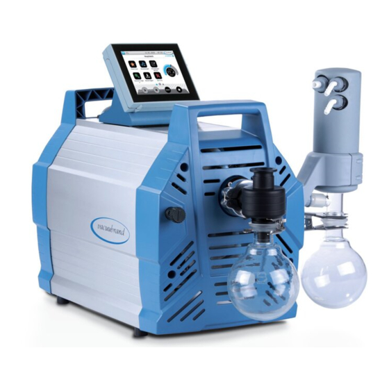
Product description Product description Pumping units of the PC 301x VARIO select series essentially consist of a diaphragm pump controlled by VARIO drive, a ® VACUU·SELECT type vacuum controller and a chiller with sep- arator. There are different versions of chiller. The difference lies in how the chillers operate. -
Page 23: Chemistry Pumping Unit Series
Product description 15 Rating plate 3.2 Chemistry pumping unit series Overview of chem- istry pumping units Description Chemistry pumping unit Pump Stage head PC 3010 VARIO select ● ● PC 3016 VARIO select ● ● PC 3012 VARIO select ● ● PC 3012 VARIO select EKP ● ● Product-specific abbreviations Product-specific ab- Separator flask, mounted at the inlet or outlet breviations Vapor condenser, mounted at the outlet ®... -
Page 24: Condensers And Chillers
Product description 3.3 Condensers and chillers 3.3.1 Separator/condenser at the inlet Connection at the separator flask Connections on the Description 1 Inlet connection vacuum IN 3.3.2 Condenser at the outlet Connection and coolant on the vapor condenser Connections on the Description 1 Coolant outlet connection EX 2 Inlet connection coolant IN, e.g., water... - Page 25 Product description ® Connections at the Peltronic vapor condenser Connections on the 1 Outlet connection EX 2 Vacuum pump connection ® 3 VACUU·BUS port 4 Power supply with ON/OFF switch ð For detailed information and descriptions of the Pel- ® tronic vapor condenser -> see...
-
Page 26: Sample Application
Product description 3.4 Sample application Local area vacuum network -> Example Local area vacuum network Description ® Example of use: VACUU·LAN , network arrangement with three valve modules Lab furniture Exhaust gas hose (diverted into a fume hood) Vacuum tubing VACUU·SELECT operating panel + VACUU·SELECT sensor PC 3012 VARIO select vacuum pumping unit 20901118_EN-US_PC301x VARIO select Serie_V1.3_100720... -
Page 27: Installation And Connection
Installation and connection Installation and connection 4.1 Transport Products from VACUUBRAND are packed in sturdy, recyclable packaging. The original packaging is accurately matched to your product for safe transport. ð If possible, please keep the original packaging, e.g., for returning the product for repair. -
Page 28: Installation
Installation and connection Please note that a pumping unit can weigh approx. 30-34 kg. We recommend using a lifting aid. Lift the unit out of the packaging by the side handles. 4.2 Installation NOTICE Condensate can damage the electronics. A large temperature difference between the storage location and the installation location can cause condensation. - Page 29 Installation and connection Vacuum pump installation -> Example Drawing showing minimum distances in the laboratory fur- niture ð Place the vacuum pump on a stable, non-vibrating, level surface. ð When installing in lab furniture, maintain a minimum dis- tance of 5 cm (2 in) to adjacent objects or surfaces. ð...
-
Page 30: Controller Base
Installation and connection 4.3 Controller base The base, controller, screw fittings and vacuum sensor are en- closed separately. Before installation, the base can be mounted on the pumping unit and the controller clipped into place. Alternatively, the controller can be clipped into a recess in the lab furniture. -
Page 31: Connection
Installation and connection 5. Plug the VACUU·BUS ca- 6. Also plug in the ble into the power connec- VACUU·BUS cables from tion on the back of the peripheral devices. Use Y controller. adapters (see acces- sories) if there are not enough connections. - Page 32 Installation and connection Connect the vacuum hose -> Example Vacuum connection at the inlet IN 1. Take a vacuum hose (a) that fits on hose nozzle SW15 (b). 2. Push vacuum hose (a) onto the hose nozzle and secure the vacuum hose, for example with a hose clip (c). Alterna- tively, you can connect a metal hose with small flange KF25 g Ordering information directly;...
-
Page 33: Exhaust Gas Connection (Ex)
Installation and connection 4.4.2 Exhaust gas connection (EX) WARNING Risk of bursting due to overpressure inside the outlet line. Inadmissibly high pressure in the outlet line can cause the vacuum pump to burst or damage seals. The outlet line (outlet, gas outlet) must always be Ø... - Page 34 Installation and connection In a closed, in-house coolant circuit, the pressure should be limited to 3 bar (44 psi). A coolant valve may only be installed in the feed line; the coolant drain must be clear and non-pressurized. Connect the coolant -> Example Coolant connection at the EK 1.
-
Page 35: Venting Connection
Installation and connection 4.4.4 Venting connection DANGER Risk of explosion by venting with air. Depending on the application, venting can cause explo- sive mixtures to form or other hazardous situations to arise. Never vent processes with air which could form an Ø... -
Page 36: Gas Ballast (Gb)
Installation and connection Vent with inert gas – connect venting valve Required connection material: hose for hose nozzle, e.g., sili- cone tube 4/5 mm. Venting valve inert ð Push hose (c) onto the connection of gas connection venting valve (b) and connect inert gas (max. 1.2 bar/900 Torr, abs.). - Page 37 Installation and connection Gas ballast valve position If ambient air is to be used as gas ballast, nothing needs to be connected at the pumping unit; gas ballast valve (a); see also g Operation with gas ballast on page 43 chapter: Use of inert gas as gas ballast – OPTION Prepare the inert gas connection (GB)
-
Page 38: Electrical Connection
Installation and connection 4.5 Electrical connection Pumping unit electrical connection -> Example Pumping unit elec- trical connection 1. Plug connector (a) of the power cord into the power connec- tion of the vacuum pump. 2. Plug power plug (b) into the power outlet. Pumping unit connected electrically. - Page 39 Installation and connection NOTICE! . ð Use the power plug which fits your power connection. ð Do not use multiple sockets connected in series as the power connection. ð The power plug also serves as a disconnector. Install the unit so that the plug can be easily disconnected from it. 20901118_EN-US_PC301x VARIO select Serie_V1.3_100720...
-
Page 40: Commissioning (Operation)
1. Switch rocker switch (a) on – switch position I. 2. Press ON/OFF button (b) on the controller. The start screen is displayed. After approx. 30 seconds, the process screen with the operating elements appears on the controller display. WEB: VACUUBRAND/Products/Gauges and controllers/Vacuum control 20901118_EN-US_PC301x VARIO select Serie_V1.3_100720... -
Page 41: Operation
Commissioning (operation) 5.2 Operation 5.2.1 User interface User interface ® VACUU·SELECT with process screen Process screen Pressure display for a process 1 Status bar 2 Analogue pressure display – pressure curve 3 Digital pressure display – pressure value (target value, actual value, pressure unit) 4 Process screen with context features 5 Screen navigation... -
Page 42: Operation
Commissioning (operation) Button Function Stop Stop application – always possible. VENT – Vent the system (option) Press button < 2 sec = vent briefly; control contin- ues. Press button > 2 sec = vent to atmospheric pres- sure; vacuum pump is stopped. Press button dur- ing venting = venting is stopped. Favorites View Favorites menu. -
Page 43: Operation With Gas Ballast
Commissioning (operation) Vent Vent 5.2.3 Operation with gas ballast Description The provision of gas ballast (= addition of gas) ensures that va- pors do not condense inside the vacuum pump but are instead ejected from the pump. This makes it possible to pump larger amounts of condensable vapors, and also prolongs the service life. -
Page 44: Shutdown (Switch Off)
Commissioning (operation) ð Observe the admissible pressure at the gas ballast connec- tion, max. 1.2 bar/900 Torr abs. If the gas volume in the vacuum pump is low, a gas ballast can be eliminated in these cases to increase the solvent re- covery rate. 5.3 Shutdown (switch off) Shut down the pumping unit Switch off pumping... - Page 45 Commissioning (operation) 2. Recommendation: Perform preventative maintenance be- fore storing the pumping unit. This is especially important if it ran more than 15,000 operating hours. 3. Close the suction and outlet lines, e.g., with the transport caps. 4. Package the pumping unit such that it is protected from dust, enclose desiccant if necessary.
-
Page 46: Troubleshooting
Troubleshooting Troubleshooting 6.1 Technical support g Error – Cause – Remedy For troubleshooting, refer to table on page 46. For technical assistance or in the event of an error, please con- tact our Service department. Only use the device if it is in perfect working condition. ð... - Page 47 Troubleshooting Error Cause Remedy Person- If necessary, use a different, external venting valve. Venting valve does Venting valve in Replace defective Specialist not operate sensor defective. components. Vacuum pump does Pumping unit Switch on Pumping Operator not start switched off. unit.
- Page 48 Troubleshooting Error Cause Remedy Person- Check gas ballast cap. Replace defective components. No or very little suc- Deposits inside the Clean and check Specialist tion power vacuum pump. pump heads. Diaphragms or Replace di- valves defective. aphragms and High level of vapor valves.
-
Page 49: Cleaning And Maintenance
Cleaning and maintenance Cleaning and maintenance WARNING Danger due to electrical voltage. Switch the device off before cleaning or maintenance Ø work. Unplug the power plug from the socket. Ø Risk from contaminated parts. Pumping hazardous media can result in hazardous substances adhering to internal parts of the pump. - Page 50 Cleaning and maintenance Replace O‑rings Clean or replace molded PTFE hose Replace pressure relief valve on EK Cleaning the pumping unit Recommended aids -> Example Recommended aids for cleaning and maintenance Description No. Item 1 Round bottom flask stand 2 Protective gloves 3 Chemical-resistant vessel + funnel 20901118_EN-US_PC301x VARIO select Serie_V1.3_100720...
- Page 51 Cleaning and maintenance Tools needed for maintenance -> Example Tools Description No. Tool Size 1 Service kit Service kit PC 3010, PC 3012 #20696839 Service kit PC 3016 #20696867 2 Diaphragm wrench #20636554 SW66 3 Flat nose pliers To secure the hose clips 4 Flat-head screwdriver To open hose clips Size 1 5 Phillips screwdriver...
-
Page 52: Cleaning
Cleaning and maintenance 7.2 Cleaning This chapter does not contain descriptions for decontamination of the product. This chapter describes simple measures for cleaning and care. ð Before cleaning, switch off the pumping unit. 7.2.1 Housing surface Clean the surfaces Clean dirty surfaces with a clean, slightly damp cloth. We rec- ommend using water or mild soapy water to moisten the cloth. -
Page 53: Clean Or Replace Ptfe Hoses
Cleaning and maintenance 7.2.3 Clean or replace PTFE hoses Maintenance provides the opportunity to check the components of the pumping unit, including the hoses. ð Clean the inside of very dirty molded hoses, e.g., using a pipe cleaner or similar. ð Replace brittle and defective molded hoses. 7.3 Vacuum pump maintenance 7.3.1 Maintenance items Positions to be maintained... -
Page 54: Preparation
Cleaning and maintenance ð On one pump head pair, first replace the di- aphragms and then the inlet/outlet valves. ð Then perform maintenance on the next pump head pairs one after the other. ð Always replace all diaphragms and valves. 7.3.2 Preparation g Controller Disassemble the controller and base, see chapter... - Page 55 Cleaning and maintenance 5. Remove the separator 6. Remove the cap from the flask and put the compo- gas ballast. nents aside. 7. Unscrew the 4 screws 8. Remove the housing sec- from the front housing sec- tion and set it aside. tion;...
- Page 56 Cleaning and maintenance You can then check the EK pressure relief valve and re- place it if damaged. 11. Pull the EK and its holder 12. Set the chiller down se- from the molded hose. curely so that no liquid can You can then check the escape.
-
Page 57: Suction/Pressure Distributor Maintenance
Cleaning and maintenance 7.3.3 Suction/pressure distributor maintenance Exploded drawing of suction/pressure distributor -> Example Pressure relief valve (only PC 3010 or PC 3012) Description Pressure relief valve + O-ring maintenance 1 Countersunk screw M4x80 2 Connection DN 25 3 Hose nozzle 4 Suction distributor 5 O-ring 40 x 2 6 Pressure relief valve D37 7 Pressure distributor... - Page 58 Cleaning and maintenance Replace pressure relief valve + O-ring -> Example Maintenance on the suction/pressure distributor (only PC 3010 or PC 3012) 1. Place the vacuum pump 2. Only open the hose clips on a clean, stable surface above the pressure distrib- as shown. utor;...
- Page 59 Cleaning and maintenance 5. Remove the suction dis- 6. Carefully remove the used tributor with the screws pressure relief valve, e.g., and put it aside. with a sturdy plastic rod or a narrow flat-head screw- driver. 7. Replace the used O-ring. 8.
-
Page 60: Replace Diaphragms And Valves
Cleaning and maintenance 11. Push the molded hoses 12. Secure the hose clips on back into place on the the hose nozzles, hose nozzles. e.g., with flat nose pliers. 7.3.4 Replace diaphragms and valves Disassemble further housing sections -> Example Disassemble the housing 1. - Page 61 Cleaning and maintenance 3. Unscrew the screws from 4. Route the cable out of the the side panel retaining recess. plate; hex key size 4. Remove the side panel Remove the right side panel (exposing the first pump head pair) 1. Unscrew the 2 outer 2.
- Page 62 Cleaning and maintenance Exploded drawing of pump head -> Example Exploded drawing of pump head pair Description Valve maintenance 1 Clamping claw + screw fittings 2 Disc springs 3 Valve terminals 4 Valves 5 O-rings size 26 x 2 Diaphragm maintenance 6 Head cover + screw fittings 7 Diaphragm clamping disc with square head screw 8 Diaphragms 9 Diaphragm support disc...
- Page 63 Cleaning and maintenance Right pump head pair -> Example Maintenance on the right pump head pair 1. Open the hose clips on the 2. Pull off the molded hoses. outer hoses. Flat-head screwdriver size 1. 3. Unscrew the socket head 4. Remove the pump head screws from the head cov- pair with the screw fittings.
- Page 64 Cleaning and maintenance Replace diaphragms -> Example Diaphragm replace- ment 1. Lift the diaphragm up- 2. Carefully position the di- wards on either side. aphragm wrench on the di- aphragm support disc and unscrew the assembly with the diaphragm wrench attached. 3.
- Page 65 Cleaning and maintenance 4. Pull out the diaphragm 5. Place the new diaphragm clamping disc and remove over the square head of the used diaphragm. the diaphragm clamping disc. Ensure that the diaphragm is inserted correctly, with the coated, light-colored side facing upwards.
- Page 66 Cleaning and maintenance 8. Hold the spacer discs 9. Next, tighten the assembly firmly and place all the with the diaphragm components carefully on wrench until it is finger- the connecting rod thread. tight. 10. Then position a torque 11. Repeat steps 1-11 to re- wrench with socket head place the next diaphragm.
- Page 67 Cleaning and maintenance Replace valves -> Example Valve replacement 1. Take the pump head pair 2. Unscrew the Torx screws. which you had set aside. Torx screwdriver size Tx20. 3. Remove the clamping 4. Remove the valve termi- claws from the valve termi- nals with the disc springs.
- Page 68 Cleaning and maintenance Depending on the pump type, the valve material is either PTFE (white) FFKM (black). -> Example Valve replacement 5. Carefully remove the used 6. Check the surfaces for O-rings and valves. dirt. 7. Clean dirty surfaces care- 8. Insert the new sealing fully.
- Page 69 Cleaning and maintenance Plan view cutout: Correct position- 9. Place the new valves on ing of valves. top and align them. IN = inlet EX = exhaust (outlet) -> Example Valve replacement 10. Place both valve terminals 11. Place the clamping claws with the disc springs on on the valve terminals and the pump heads.
- Page 70 Cleaning and maintenance 14. Slide the molded hoses 15. Secure the hose clips on back onto the hose noz- the hose nozzles, zles. e.g., with flat nose pliers. Bottom pump head pair -> Example Maintenance on the bottom pump head pair ð Follow the same procedure to replace the diaphragms and g Right valves as described for the right pump head pair pump head pair...
- Page 71 Cleaning and maintenance Left and top pump head pair -> Example Maintenance on the left and top pump head pair 1. Turn the pumping unit with 2. Support the pumping unit, the side panel upwards. e.g., with rigid foam below the housing of the fre- quency converter.
- Page 72 Cleaning and maintenance 5. Follow the same procedure to replace the diaphragms and g Right valves as described for the right pump head pair pump head pair on page 63. Assemble the device and housing sections Before restarting the pumping unit, all previously removed parts of the device and housing must be fixed back in place.
- Page 73 Cleaning and maintenance 5. Wind the screw fittings into 6. Stand the pump on its rub- the side panel; hex key ber feet. size 5. 7. Wind in the 2 outer screws 8. Secure the cable in the of the retaining plate; hex rear recess.
- Page 74 Cleaning and maintenance 11. Wind in the screws of the 12. Push the molded hose for housing section; hex key the EK into place. size 4. Assemble the EK 13. Secure the hose clip, 14. Slide the EK and its holder e.g., with flat nose pliers.
- Page 75 Cleaning and maintenance Mount the front housing cover 17. Replace the front housing 18. Wind in the screws of the section. housing section; hex key size 4. Mount attachments 19. Place the cap on the gas 20. Secure the separator flask ballast.
- Page 76 Cleaning and maintenance 23. Secure the controller on 24. Plug in the power plug. the pumping unit and con- nect all cables. If maintenance work has been completed in full: ð Connect the hoses for operation. ð Connect the pumping unit to the power supply. Pumping unit is ready to be returned to use.
-
Page 77: Appendix
Appendix Appendix 8.1 Technical data Product designation Chemistry pumping unit series Product names PC 3010 VARIO select PC 3016 VARIO select PC 3012 VARIO select PC 3012 VARIO select EKP Technical data Technical data Ambient conditions (US) Ambient temperature 10–40 °C 50‑104°F Altitude, max. - Page 78 Appendix Venting valve (venting with Silicone rubber hose 4‑5 inert gas) – OPTION Coolant EK 2x (+2x ) hose nozzles DN 6‑8 Exhaust gas, outlet EX Hose nozzle DN 8‑10 Cold connector + power connection CEE, CH, CN, UK, IN, ® Plug-in connector VACUU·BUS Electrical data...
-
Page 79: Wetted Materials
Appendix PC 3012 Max. pumping speed 15 m 8.8 cfm Ultimate vacuum, abs. 1.5 mbar 1.1 Torr Ultimate vacuum with GB, 3 mbar 2.2 Torr abs. Number of cylinders/stages PC 3016 Max. pumping speed 20 m 11.8 cfm Ultimate vacuum, abs. 70 mbar 53 Torr Ultimate vacuum with GB, 100 mbar 75 Torr abs. Number of cylinders/stages Weights* and dimensions (l x w x h) (US) -
Page 80: Rating Plate
Appendix Diaphragm clamping disc ETFE carbon fiber reinforced Diaphragms PTFE Valves PC 3010, PC 3012 FFKM Valves PC 3016 PTFE O-rings Valve terminal ECTFE, carbon fiber reinforced Pumping unit Inlet PP, PE Outlet Distributor head PPS glass fiber reinforced O-ring on separator Fluoroelastomer, NBR Pressure relief valve at the vapor Silicone rubber, PTFE film condenser... -
Page 81: Ordering Information
Appendix Pumping unit rating plate, general -> Example Rating plate detail Product series/type Serial number Year of manufacture/month Pumping speed Ultimate vacuum Power supply ATEX specification* Manufacturer * Indicating documentation, group and category, marking G (gas), type of protection, explosion group, temperature class (see also: Approval for ATEX equipment category). - Page 82 Power cord 20612058 20676021 20635997 20635365 20612065 20612058 ð VACUUBRAND > Support > Instructions for repair > Chemistry pumping units. Sources of supply International sales Purchase original accessories and original spare parts from a offices and distribu- subsidiary of VACUUBRAND GMBH + CO KG or your local dis- tion tributor.
-
Page 83: Service Information
Immediate repairs processing On-site service (on request) Calibration (DAkkS-accredited) With Health and Safety Clearance form: return, disposal Visit our website for further information: www.vacuubrand.com. Service handling Follow these headings: VACUUBRAND > Support > Service Reduce downtime, speed up processing. Please have the required data and documents at hand when contacting our Service Depart- ment. -
Page 84: Eu Declaration Of Conformity
Appendix 8.6 EU Declaration of Conformity 20901118_EN-US_PC301x VARIO select Serie_V1.3_100720... -
Page 85: Index
Index Index Measurement chamber.... 80 Misuse ........ 13 Abbreviations used ..... 10 Modular manuals ...... 6 Additional symbols...... 8 Mount the base to the pumping unit Ambient conditions ..... 29 .......... 30 ATEX equipment category.. 21 Mount the side panel .... 72 ATEX equipment category and pe- ripheral devices ...... 21 Note load capacity ...... 18 Connect the exhaust gas hose ... 33 Connect the outlet....... 33... - Page 86 Index Recommended aids for cleaning and maintenance .... 50 Responsibility matrix.... 15 Rough vacuum...... 11 Safety information....... 12 Safety precautions ...... 16 Separator flask...... 23 Separator flask connections .. 24 Suction/pressure distributor mainte- nance........ 58 Suction/pressure distributor mainte- nance (option)...... 57 Surface temperatures .... 19 Switch on ........ 40 Switch on pumping unit.... 40 Target groups ...... 15 Technische Daten....... 77 User interface ...... 41...
- Page 87 20901118_EN-US_PC301x VARIO select Serie_V1.3_100720...
- Page 88 Technology for vacuum systems Manufacturer: VACUUBRAND GMBH + CO KG Alfred‑Zippe‑Str. 4 97877 Wertheim GERMANY Phone: Switch- +49 9342 808-0 board: Sales: +49 9342 808-5550 Service: +49 9342 808-5660 Fax: +49 9342 808-5555 Email: info@vacuubrand.com Web: www.vacuubrand.com...
Need help?
Do you have a question about the PC301 VARIO select Series and is the answer not in the manual?
Questions and answers