vacuubrand PC 3010 NT VARIO select Instructions For Use Manual
Chemistry pumping unit
Hide thumbs
Also See for PC 3010 NT VARIO select:
- Instructions for use manual (96 pages) ,
- Instructions for use manual (152 pages)

Related Manuals for vacuubrand PC 3010 NT VARIO select


Summary of Contents for vacuubrand PC 3010 NT VARIO select
- Page 1 Chemistry pumping unit series PC 3010 NT VARIO select PC 3016 NT VARIO select PC 3012 NT VARIO select PC 3012 NT VARIO select EKP Instructions for use Original instructions EN-US 20901552...
- Page 2 Head office: +49 9342 808-0 Sales: +49 9342 808-5550 Service: +49 9342 808-5660 Fax: +49 9342 808-5555 E-mail: info@vacuubrand.com Web: www.vacuubrand.com Thank you for purchasing this product from VACUUBRAND GMBH + CO KG. You have chosen a state-of-the-art, high-quality prod- uct. 20901552_EN-US_PC301x NT V.sel (Ser.Atb_Ha)_V1.1_160822...
-
Page 3: Table Of Contents
TABLE OF CONTENTS About this manual User information ..............5 Manual structure ..............6 Presentation conventions............7 Symbols and pictograms ............8 Action instructions ..............9 Abbreviations ................. 10 Explanation of terms.............. 11 Safety instructions Use ..................12 2.1.1 Proper use..............12 2.1.2 Improper use .............. - Page 4 4.4.2 Exhaust connection (OUT) ..........33 4.4.3 Coolant connection on the condenser......34 4.4.4 Venting connection ............35 4.4.5 Gas ballast (GB) ............. 37 Electrical connection ............. 39 Operation Switching on................41 Operation with controller ............42 5.2.1 Operator interface............42 5.2.2 Operation...............
-
Page 5: About This Manual
Chemistry pumping unit PC 301x NT VARIO select. Copyright © Copyright The content of this User manual is protected by copyright law. copyright law Copies for internal purposes are permitted, e.g. for trainings. © VACUUBRAND GMBH + CO KG 20901552_EN-US_PC301x NT V.sel (Ser.Atb_Ha)_V1.1_160822... -
Page 6: Manual Structure
In case of an incomplete User manual, you can request a re- placement from us. Alternatively, our download portal is avail- able to you: www.vacuubrand.com Call us or write to us if you have any other questions about the product, need additional information or want to give us feed- back on the product. -
Page 7: Presentation Conventions
About this manual 1.3 Presentation conventions Warning messages Presentation of DANGER warning messages Warning of imminent danger. Failure to observe this warning may result in imminent danger to life or severe injury. Please follow the instructions for prevention! Ø WARNING Warning of a potentially dangerous situation. -
Page 8: Symbols And Pictograms
About this manual 1.4 Symbols and pictograms This instruction manual uses symbols and pictograms. These safety symbols and pictograms indicate specific dangers or requirements when handling the product. Warning signs with safety symbols on the product provide a visualization of the potential hazard. Safety symbols Explanation of General danger sign. -
Page 9: Action Instructions
About this manual 1.5 Action instructions Action instructions (simple) Action instructions ð You are requested to take action. Result of the action Action instructions (multiple steps) 1. First action step 2. Next action step Result of the action Action instructions that require several steps must be followed in the order they are described. -
Page 10: Abbreviations
About this manual 1.6 Abbreviations Abbreviations used >/ No greater than abs. Absolute Separator flask Atmospheric pressure (bar graph, program) Diameter Diameter nominal Emissions condenser Peltronic emissions condenser or Peltronic EK Outlet (exhaust, exit), exhaust gas connection ATEX device marking Fluoropolymer rubber Gas type ind. -
Page 11: Explanation Of Terms
Dry ice condenser Cooling condenser with receiving flask and dry ice as cooling medium installed at the outlet (pressure side). VACUU·BUS VACUUBRAND bus system for the communication of pe- ripheral devices with VACUU BUS-capable measuring equipment and controllers. VACUU·BUS ad-... -
Page 12: Safety Instructions
Safety instructions Safety instructions The information in this chapter must be observed by all persons who work with the device described here. The safety instructions are valid for all life stages of the product. 2.1 Use The device may only be used in perfect technical condition. 2.1.1 Proper use Proper use A chemistry pumping unit of the PC 301x NT VARIO select product... -
Page 13: Improper Use
Safety instructions 2.1.2 Improper use Improper use Improper use or any use that does not correspond with the technical data can lead to personal or material damage. Improper use is considered: use that contradicts the proper use, operation in unauthorized ambient and operating conditions, operation with obvious faults, damages or defective safety equipment, unauthorized extensions and modifications, especially when... -
Page 14: Responsibilities
Safety instructions 2.2 Responsibilities Follow the instructions for all actions as they are specified in this in- struction manual. Responsibilities of the operator Operator responsibil- The operator defines the responsibilities and ensures that only ities trained or qualified personnel work on the vacuum system. This ap- plies in particular to connection, assembly work, maintenance tasks and fault elimination. -
Page 15: Target Group Description
Fault elimination Device fuse replacement Maintenance Repair Repair order Cleaning, simple Emptying separator Decommissioning Decontamination 3 See also homepage: VACUUBRAND > Support > Repair instructions 4 Or have decontamination carried out by a qualified service provider. 20901552_EN-US_PC301x NT V.sel (Ser.Atb_Ha)_V1.1_160822... -
Page 16: Protective Clothing
ð Wear your personal protection equipment when handling chemicals. 2.5 Safety measures Manufacturer mea- Products of VACUUBRAND GMBH + CO KG are subject to high qual- sures ity control requirements in terms of safety and operation. Each product is put through an extensive test program before delivery. -
Page 17: Laboratory And Work Materials
Safety instructions 2.6 Laboratory and work materials DANGER Hazardous materials leak at the outlet. When operating the vacuum, hazardous, toxic substances can leak into the ambient air at the outlet. Please observe the safety regulations for handling haz- Ø ardous materials and media. Remember that adhesive process media can present a Ø... -
Page 18: Possible Sources Of Danger
Safety instructions Preventing foreign bodies inside the pump Observing the vac- Particles, liquids and dust are not permitted inside the vacuum uum pump design pump. ð Do not pump any substances that can form deposits inside the vacuum pump. ð Install suitable separators and/or filters in front of the inlet. Suitable filters are chemical resistant, clog-free and ensure a constant flow rate. - Page 19 Safety instructions Preventing condensate return flow Preventing backlog Condensate can damage the pump head. Condensate must never in the exhaust line flow back through the hose line into the outlet and into the pump head. Liquid is not allowed to collect in the exhaust line. ð...
- Page 20 Safety instructions Dangers due to hot surfaces or overheating Surface tempera- The surface of vacuum pumps can reach temperatures greater than tures 70 °C during operation, especially when vacuuming heated media. ð Avoid direct contact with the surface or wear heat-resistant safety gloves if contact cannot be excluded.
-
Page 21: Motor Protection
Safety instructions 2.8 Motor protection CAUTION Limited winding protection with supply voltages less than 115 V AC. With supply voltages less than 115 V AC, the self-locking mechanism of the winding protection can be limited. After cooling, this can cause the pump to start automatically. When overheating, switch the pump off to avoid an auto- Ø... -
Page 22: Disposal
Safety instructions ATEX device category The ATEX device category of the of the vacuum pump depends on and peripheral de- the connected components and the periphery. Components and pe- vices ripheral devices must have the same or higher ATEX classification. Preventing sources The use of ventilation valves is only permitted if it is ensured that of ignition... -
Page 23: Product Description
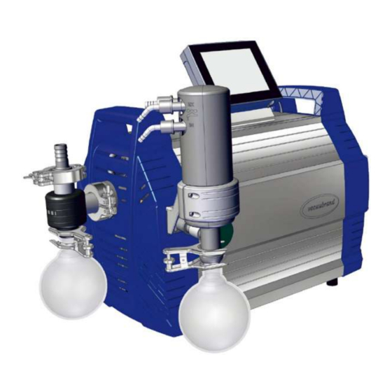
Product description Product description Pumping units of the PC 301x NT VARIO select series essentially con- sist of a diaphragm pump controlled by VARIO drive, a VACUU·SE- LECT vacuum controller and a chiller with separator. There are dif- ferent versions of chiller. The difference lies in how the chillers oper- ate. -
Page 24: Chemistry Pumping Unit Series
Product description 15 Nameplate 16 Round bottom flask at the inlet 17 Housing section with handle, front 18 Round bottom flask at outlet 3.2 Chemistry pumping unit series Overview of chem- istry pumping units Meaning Chemistry pumping unit Pump Steps head PC 3010 NT VARIO select ●... -
Page 25: Condensers And Coolers
Product description PC …. Chemistry pumping unit with type code 3.3 Condensers and coolers 3.3.1 Separator/condenser at inlet Connection on separator flask Connections on AK Meaning 1 Vacuum inlet connection IN 3.3.2 Condenser at outlet Connection and coolant on emission condenser Connections on EK Meaning 1 Outlet connection coolant EX... -
Page 26: Application Example
Product description 3.4 Application example Local vacuum network -> Example Local area vacuum network Meaning ® Example of use: VACUU·LAN , network arrangement with three valve mod- ules Laboratory furniture Exhaust gas hose (diverted into a fume hood) Vacuum tubing VACUU·SELECT operating panel + VACUU·SELECT sensor PC 3012 NT VARIO select vacuum pumping unit 20901552_EN-US_PC301x NT V.sel (Ser.Atb_Ha)_V1.1_160822... -
Page 27: Installation And Connection
Installation and connection Installation and connection 4.1 Transport Products from VACUUBRAND are packaged in stable, recyclable packaging. The original packaging is customized to your product for safe transport. ð If possible, keep the original packaging, e.g. for sending in for re- pairs. -
Page 28: Installation
Installation and connection Please note that a pumping unit can weigh approx. 30-34 kg. We recommend using a lifting aid. Lift the unit out of the packaging by the side handles. 4.2 Installation NOTICE Condensate can damage the electronics. A large difference in temperature between the storage location and the installation site can lead to the formation of condensate. - Page 29 Installation and connection Installing the vacuum pump -> Example Sketch of minimum distances in labora- tory furniture ð Place the vacuum pump on a stable, vibration-free, level sur- face. ð When installing laboratory furniture, maintain the minimum distance of 5 cm (2 in.) to adjacent objects or surfaces. ð...
-
Page 30: Controller Base
Installation and connection 4.3 Controller base The holding base, controller, screw fasteners and vacuum sensor are enclosed in a separate box. Before installation, you can mount the holding base on the pumping unit, attach the controller in it and connect the VACUU BUS cable; see the following assembly description. -
Page 31: Connection (Supply Connections)
Installation and connection 5. Plug the VACUU BUS cable 6. Also plug in the VACUU BUS into the power connector on cable of peripheral devices, the back side of the con- such as a vacuum sensor. troller. Use Y-adapters (see acces- sories) if there are not enough connections. - Page 32 Installation and connection Connecting the vacuum hose -> Example Vacuum connection at inlet IN You will achieve the optimal vacuum for your application if you ob- serve the following points: ð Connect the shortest possible vacuum line with the maximum possible cross-section. ð...
-
Page 33: Exhaust Connection (Out)
Installation and connection 4.4.2 Exhaust connection (OUT) WARNING Risk of bursting due to excess pressure in the ex- haust line. Unacceptably high pressure in the exhaust line may cause the vacuum pump to burst or damage seals. The exhaust line (outlet, gas outlet) must always be open Ø... -
Page 34: Coolant Connection On The Condenser
Installation and connection 4.4.3 Coolant connection on the condenser Coolant connection An emission condenser EK has one connection for coolants. Water or Inflow and outflow liquid in the circuit of a recirculating chiller, for example, is suitable for cooling. In a closed, internal coolant circuit, the pressure should be lim- ited to 3 bar (44 psi). -
Page 35: Venting Connection
Installation and connection 4.4.4 Venting connection DANGER Explosion risk due to air ventilation. Depending on the process, a potentially explosive mixture can form during ventilation, or other dangerous situations can occur. Never ventilate processes with air in which a potentially Ø... - Page 36 Installation and connection Vent with inert gas – connect venting valve Required connection material: Hose for hose nozzle, e.g., silicone tube 4/5 mm. Venting valve inert ð Push hose (c) onto the connection of gas connection venting valve (b) and connect inert gas (max. 1.2 bar/900 Torr, abs.).
-
Page 37: Gas Ballast (Gb)
Installation and connection 4.4.5 Gas ballast (GB) Use ambient air as gas ballast DANGER Explosion risk due to air as gas ballast. By using air as a gas ballast, a small amount of oxygen en- ters the inside of the vacuum pump. Depending on the process, a potentially explosive mixture can form due to oxygen in the air, or other dangerous situations can occur. - Page 38 Installation and connection Use of inert gas as gas ballast – OPTION Prepare the inert gas connection (GB) ð Remove the black gas ballast cap and connect a gas ballast adapter in its place. On request, we can send you connection options and adapters for hose nozzles or small flanges.
-
Page 39: Electrical Connection
Installation and connection 4.5 Electrical connection Connecting the pumping unit to the electrical system -> Example Electrical connection of the pumping unit 1. Plug the socket (a) of the power cable into the power connec- tion of the vacuum pump. 2. Connect the power plug (b) to the power outlet. Pumping unit connected to the electrical system. - Page 40 Installation and connection NOTICE! . ð Use the power plug that matches your power connection. ð Do not use multiple-socket power strips as a power connection. ð The power plug also works as a circuit breaker. Set up the de- vice so that the plug can be easily disconnected from it. Connection options for vacuum accessories The VACUU BUS interface functions as the power supply and control line for vacuum accessories.
-
Page 41: Operation
1. Switch on the rocker switch (a) – switch position I. 2. Press the ON/OFF button (b) on the controller. Display with start screen. After approx. 30 seconds, the process display appears with the control elements in the display of the controller. WEB: VACUUBRAND/Produkte/Messgeräte und Controller/Vakuum regeln 20901552_EN-US_PC301x NT V.sel (Ser.Atb_Ha)_V1.1_160822... -
Page 42: Operation With Controller
Operation 5.2 Operation with controller 5.2.1 Operator interface Operator interface ® VACUU·SELECT with process display Process display Pressure display for a process 1 Status bar 2 Analog pressure display – pressure curve 3 Digital pressure display – pressure value (target value, actual value, pres- sure unit) 4 Process display with context functions 5 Screen navigation... -
Page 43: Operation
Operation Controls Controls Button Function Vacuum controller Start Start an application – only in the process display Stop Stop an application – always possible. VENT – Ventilate system (Option) Button press < 2 Sec. = briefly ventilate, regulation continues. Button press > 2 Sec. = ventilate to atmospheric pres- sure, vacuum pump is stopped. - Page 44 Operation Stopping the vacuum controller Stop Ventilating Ventilating 20901552_EN-US_PC301x NT V.sel (Ser.Atb_Ha)_V1.1_160822...
-
Page 45: Operation With Gas Ballast
Operation 5.2.3 Operation with gas ballast Meaning The supply from the gas ballast (= gas addition) ensures that vapors are not condensed in the vacuum pump; instead, they are emitted out of the pump. This allows greater amounts of condensable va- pors to be pumped, which extends the service life. -
Page 46: Switching Off (Decommissioning)
Operation 5.3 Switching off (decommissioning) Switching off the pumping unit Switching off, e.g. 1. Stop the process and allow the pumping unit to continue run- taking the pumping ning for approx. 30 minutes with open gas ballast or open inlet unit out of operation (IN). -
Page 47: Storage
Operation 5.4 Storage Storing the pumping unit 1. Clean the The pumping unit if it is dirty. 2. Recommendation: Carry out preventative maintenance before you put The pumping unit into storage. Especially if it has been in operation for more than 15,000 hours. 3. -
Page 48: Troubleshooting
Troubleshooting Troubleshooting 6.1 Technical assistance To find and eliminate errors, use the table g Error – cause – correc- tive measure on page 48. For technical assistance or in case of faults, please contact our Ser- vice department. The device should only be operated in perfect technical condition. ð... - Page 49 Troubleshooting Error Cause Corrective measure Personnel Use another external ventilation valve if necessary. Ventilation valve Ventilation valve sen- Replace defective Qualified does not switch sor defective. components. employee Vacuum pump does Pumping unit Switch on Pumping Operator not start switched off. unit.
- Page 50 Troubleshooting Error Cause Corrective measure Personnel Check the gas ballast cap. Replace defective components. No suction capacity Deposits in the vac- Clean and test pump Qualified or very little uum pump. heads. employee Membrane or valves Replace the mem- defective. brane and valves.
-
Page 51: Cleaning And Maintenance
Cleaning and maintenance Cleaning and maintenance WARNING Danger due to electrical voltage. Switch off the device before cleaning or maintenance. Ø Disconnect the power plug from the power outlet. Ø Danger due to contaminated components. When pumping dangerous media, hazardous materials can adhere to interior pump components. -
Page 52: Information On Service Activities
Cleaning and maintenance 7.1 Information on service activities Recommended maintenance interval Maintenance inter- Maintenance intervals As required 15,000 h vals Replace membranes Replace valves Replace O-rings Clean or replace PTFE molded hose Replace pressure release valve on EC Clean pumping unit Recommended auxiliary equipment ->Example Recom- mended auxiliary... - Page 53 Cleaning and maintenance Tools needed for maintenance -> Example Tools Meaning No. Tool Size 1 Seal set Seal set PC 3010, PC 3012 #20696839 Seal set PC 3016 #20696867 2 Membrane wrench #20636554 SW66 3 Flat-nose pliers Closing hose clamps 4 Flat-head screwdriver Opening hose clamps Size 1 5 Phillips-head screwdriver Screw fasteners for controller holding base...
-
Page 54: Cleaning
Cleaning and maintenance 7.2 Cleaning This chapter does not describe how to decontaminate the product. Simple cleaning and care measures are described here. ð Before cleaning, switch off the pumping unit. CAUTION Risk of burning due to hot surfaces An elevated exhaust gas temperature can lead to hot sur- faces on the instrument and on attached components, such as glass flasks. -
Page 55: Emptying The Glass Flask
Cleaning and maintenance 7.2.2 Emptying the glass flask Removing and emptying the glass flask -> Example Emptying the glass flask 1. Open the joint clamp and re- 2. Empty the glass flask into a move the glass flask. suitable container, e.g. a chemical-resistant canister. -
Page 56: Vacuum Pump Maintenance
Cleaning and maintenance 7.3 Vacuum pump maintenance 7.3.1 Maintenance items Items to receive maintenance -> Example Maintenance of pump heads Meaning Maintenance items and sequence 1 Silicone pressure release valve EC #20638821 2 Suction-pressure distributer (behind inlet separator) 3 Pump head pair, right 4 Pump head pair, bottom 5 Pump head pair, left 6 Pump head pair, top... - Page 57 Cleaning and maintenance Dismantling device and housing parts -> Example Preparing for mainte- nance 1. Switch off the pumping unit 2. Remove the glass flask and and disconnect the power connected hoses from the plug. inlet IN. 3. Remove the glass flask and 4.
- Page 58 Cleaning and maintenance 7. Remove the 4 screws from 8. Take the housing section off the front housing section; and set it aside. hexagon socket wrench size -> Example Disassembling the EC 9. Open the union nut from the 10. Remove the 2 screws from inflow EC.
- Page 59 Cleaning and maintenance 11. Pull the EC together with the 12. Put the cooler down safely bracket from the molded so that no liquid can leak hose. Here you can check out. the pressure release valve of the EC and replace it in case of damage.
-
Page 60: Replacing The Membrane And Valves
Cleaning and maintenance 7.3.3 Replacing the membrane and valves Dismantling other housing parts -> Example Dismantling the housing 1. Remove the 4 screws from 2. Remove the housing section the rear housing section; and set it aside. hexagon socket wrench size 3. - Page 61 Cleaning and maintenance Removing the side panels Removing the right- hand side panel (uncovering the first pump head pair) 1. Remove the 2 outer screws 2. Carefully set the pump to from the retaining plate; the side. hexagon socket wrench size 3.
- Page 62 Cleaning and maintenance Exploded-view drawing of pump head -> Example Explosion-view draw- ing of pump head pair Meaning Valve maintenance 1 Clamping bracket + screw fasteners 2 Cup springs 3 Valve clusters 4 Valves 5 O-rings Size 26 x 2 Membrane maintenance 6 Head cover + screw fasteners 7 Membrane spring washer with square head screw 8 Membrane 9 Membrane support disc...
- Page 63 Cleaning and maintenance Pump head pair, right -> Example Maintenance of pump head pair, right-side 1. Open the hose clamps of the 2. Pull the molded hoses off. outer hoses. Flat-head screwdriver size 1. 3. Unscrew the hexagon 4. Remove the pump head pair socket screws from the head with the screw fasteners.
- Page 64 Cleaning and maintenance Replacing membranes -> Example Membrane replace- ment 1. Fold the membrane in on 2. Carefully position the mem- the sides. brane wrench onto the membrane support disc and unscrew the assembly with the membrane wrench fixed in place. 3.
- Page 65 Cleaning and maintenance 4. Pull the membrane spring 5. Place the new membrane washer out and remove the onto the square bolt of the used membrane. membrane spring washer. Make sure that you install membrane correctly, with the coated, light side on top.
- Page 66 Cleaning and maintenance 8. Hold onto the spacers and 9. Tighten the assembly by carefully place all compo- hand at first using the mem- nents into the threaded hole brane wrench. of the connecting rod. 10. Then place a torque wrench 11.
- Page 67 Cleaning and maintenance Replacing valves -> Example Valve replacement 1. Take the pump head pair 2. Unscrew the Torx screws. that was set aside. Torx screwdriver size Tx20. 3. Remove the clamping 4. Remove the valve clusters bracket from the valve clus- with the cup springs.
- Page 68 Cleaning and maintenance -> Example Valve replacement 5. Carefully remove the used 6. Check the surfaces for soil- O-rings and valves. ing. 7. Clean soiled surfaces care- 8. Insert new sealing rings into fully. the notches. Top view detail: Correct positioning of 9.
- Page 69 Cleaning and maintenance -> Example Valve replacement 10. Place both valve clusters 11. Place the clamping brackets with the cup springs onto onto the valve clusters and the pump heads. tighten the screws by hand at first. Then tighten these with a torque wrench to 3 12.
- Page 70 Cleaning and maintenance 14. Slide the molded hoses back 15. Close the hose clamps on onto the hose nozzles. the hose nozzles, e.g. with flat nose pliers. Pump head pair, bottom -> Example Maintenance of pump head pair, bot- ð To change the membranes and valves, proceed exactly as de- g Pump head pair, scribed for the pump head pair, right-side right...
- Page 71 Cleaning and maintenance 3. Unscrew the screw fasteners 4. Lift the side panel from the of the side panel; hexagon pump. wrench size 5. (a) Pump head pair, left (b) Pump head pair, top 5. To change the membranes and valves, proceed exactly as de- scribed for the pump head pair, right-side g Pump head pair, right...
- Page 72 Cleaning and maintenance Assembling the side panels 1. Attach the side panels onto 2. Tighten the screw fasteners the pump. of the side panel; hexagon wrench size 5. 3. Turn the pumping unit up- 4. Attach the side panels onto right and make sure that it is the pump.
- Page 73 Cleaning and maintenance 7. Tighten the 2 outer screws 8. Attach the cable in the rear from the retaining plate; gap. hexagon socket wrench size Assembling the rear housing cover 9. Tighten the screws from the 10. Attach the rear housing sec- side panel retaining plate;...
- Page 74 Cleaning and maintenance 11. Tighten the screws from the 12. Attach the molded hose for housing section; hexagon the EC. socket wrench size 4. Assembling the EC 13. Close the hose clamp, e.g. 14. Push the EC together with with flat nose pliers. the bracket onto the molded hose.
- Page 75 Cleaning and maintenance 17. Attach the front housing 18. Tighten the screws from the section. housing section; hexagon socket wrench size 4. Assembling attach- ment parts 19. Place the cap onto the gas 20. Fasten the inlet separator to ballast. the tension ring.
- Page 76 Cleaning and maintenance If the maintenance work is fully completed: ð Connect the hosing for operation. ð Connect the pumping unit to the power supply. Pumping unit ready for restart. Without reconnection -> Pumping unit prepared for stor- age. 20901552_EN-US_PC301x NT V.sel (Ser.Atb_Ha)_V1.1_160822...
-
Page 77: Device Fuse Replacement
Cleaning and maintenance 7.3.4 Device fuse replacement At the rear of the pumping unit, at the power supply, there are 2 de- vice fuses, type: 8 AT 5x20. Replace device fuse -> Example Check and replace the device fuse 1. First unplug the power con- 2. -
Page 78: Annex
Annex Annex 8.1 Technical data Product description Chemistry pumping unit series Product names PC 3010 NT VARIO select PC 3016 NT VARIO select PC 3012 NT VARIO select PC 3012 NT VARIO select EKP Technical data Technical data Ambient conditions... - Page 79 Annex Ventilation valve (ventilation Silicon rubber hose 4‑5 with inert gas) – OPTION Coolant EK 2x (+2x) hose nozzle DN 6‑8 Exhaust, outlet EX Hose nozzle DN 8‑10 Cold-device plug + power connection CEE, CH, CN, UK, IN, US ® Plug-in connector VACUU·BUS Electrical data (US)
- Page 80 Annex Weight* 29.7 kg 65.5 lb PC 3012 NT VARIO 616 mm x 387 mm 24.25 in select x 450 mm x 15.24 in x 17.72 in Weight* 29.7 kg 65.5 lb PC 3012 NT VARIO 616 mm x 387 mm 24.25 in select EKP x 450 mm x 15.24 in x 17.72 in Weight* 33.6 kg 74 lb * without cable PC 3010 NT VARIO select Pumping speed, max. 12.8 m 7.54 cfm End vacuum, absolute 0.6 mbar 0.45 Torr End vacuum with GB, absolute 1.2 mbar 0.9 Torr...
-
Page 81: Wetted Materials
Annex 8.2 Wetted materials Materials affected by Component Materials affected by media media Pump Head cover Carbon fiber reinforced ETFE Diaphragm clamping disc Carbon fiber reinforced ETFE Diaphragm PTFE Valves PC 3010, PC 3012 FFKM Valves PC 3016 PTFE O-ring Valve terminal Carbon fiber reinforced ECTFE Pumping unit Inlet PP glass fiber reinforced... -
Page 82: Rating Plate
Annex Hose nozzle Seal on ventilation valve FFKM 8.3 Rating plate Specifications from ð In case of error, take note of the type and serial number from the the type plate type plate. ð When contacting our service department, provide the type and serial number from the type plate. -
Page 83: Order Data
Annex 8.4 Order data Ordering information Chemistry pumping unit series *Order no. for pumping units PC 3010 NT VARIO select 257448xx PC 3012 NT VARIO select 257438xx PC 3012 NT VARIO select EKP 25743874 PC 3016 NT VARIO select 257418xx * Order no. - Page 84 International agents Purchase original accessories and original replacement parts from a and dealers branch office of VACUUBRAND GMBH + CO KG or from your local dealer. ð Information about the complete range of products can be found in the current product catalog.
-
Page 85: Service Information
Service procedure Follow the description at: VACUUBRAND > Support > Service Reduce downtimes, speed up processing. When contacting our service department, please have the required information and documents ready. ð Your order can be assigned quickly and easily. -
Page 86: Eu Declaration Of Conformity
Annex 8.6 EU declaration of conformity 20901552_EN-US_PC301x NT V.sel (Ser.Atb_Ha)_V1.1_160822... -
Page 87: Ukca Conformity Declaration
Annex 8.7 UKCA conformity declaration 20901552_EN-US_PC301x NT V.sel (Ser.Atb_Ha)_V1.1_160822... -
Page 88: Index
Index Index Abbreviations used ...... 10 Labels and signs ....... 20 Action instructions (image descrip- Looking out for dangers during venti- tion) .......... 9 lation .......... 19 Additional symbols ...... 8 Ambient conditions...... 29 Maintenance interval ....... 52 Assembling the side panels ..... 72 Maintenance of pump heads ... 56 ATEX device category ....... 21 Materials affected by media .... 81 ATEX device category and peripheral... - Page 89 Index Proper use......... 12 Qualification description .... 15 Recommended auxiliary equipment for cleaning and maintenance .. 52 Replace device fuse...... 77 Restart procedure ...... 21 Rough vacuum........ 11 Safety instructions ...... 12 Separator flask ......... 24 Separator flask connections.... 25 Surface temperatures ...... 20 Switching on ........ 41 Switching on the pumping unit .. 41 Target groups ........ 15 Technical data ........ 78 Uncovering the pump head pair.. 61...
- Page 90 20901552_EN-US_PC301x NT V.sel (Ser.Atb_Ha)_V1.1_160822...
- Page 91 20901552_EN-US_PC301x NT V.sel (Ser.Atb_Ha)_V1.1_160822...
- Page 92 VACUUBRAND > Support > Manuals Manufacturer: VACUUBRAND GMBH + CO KG Alfred‑Zippe‑Str. 4 97877 Wertheim GERMANY Head office: +49 9342 808-0 Sales: +49 9342 808-5550 Service: +49 9342 808-5660 Fax: +49 9342 808-5555 E-mail: info@vacuubrand.com Web: www.vacuubrand.com...
Need help?
Do you have a question about the PC 3010 NT VARIO select and is the answer not in the manual?
Questions and answers