Sign In
Upload
Manuals
Brands
Kessel Manuals
Control Unit
Control Unit Pumpfix 230V
Kessel Control Unit Pumpfix 230V Manuals
Manuals and User Guides for Kessel Control Unit Pumpfix 230V. We have
1
Kessel Control Unit Pumpfix 230V manual available for free PDF download: Instructions For Installation, Operation And Maintenance
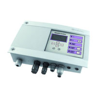
Kessel Control Unit Pumpfix 230V Instructions For Installation, Operation And Maintenance (120 pages)
Brand:
Kessel
| Category:
Control Unit
| Size: 6.43 MB
Table of Contents
Deutsch
2
Table of Contents
2
1 Allgemeines
3
Einleitung und Begrüßung
3
Produktbeschreibung, Allgemein
3
Allgemeine Hinweise zu dieser Betriebs- und Wartungsanleitung
4
Typenschild
4
Lieferumfang
5
Baugruppen und Funktionselemente
5
Display und Bedienfeld, Anzeigen
6
Diodenanzeige Schaltgerät
6
2 Sicherheit
7
Bestimmungsgemäße Verwendung
7
Personalauswahl und -Qualifikation
7
Organisatorische Sicherheits-Maßnahmen
7
Gefahren, die vom Produkt Ausgehen
7
Gefahr durch Elektrischen Strom und Kabel
7
3 Montage
8
Schaltgerät Montieren
8
Abwasserpumpe(N) Anschließen
8
Optische Sonde (Niveaugeber) Anschließen
9
Alarmsonde Anschließen
10
Erstinbetriebnahme
10
Initialisierung Durchführen
10
Funktionskontrolle der Sonden
11
Einstellungen, Menü
12
4 Betrieb
13
Einschalten
13
Alarm Quittieren
13
Wartung
13
Ausschalten
13
5 Technische Daten
14
Anschlusskabel Pumpe / Sonden Kürzen oder Verlängern
14
Menüstruktur
15
Schaltplan
17
6 Wartung
18
Wartungstermin Einstellen
18
Selbstdiagnosesystem (SDS)
18
Fehlersuche
18
7 Konformitätserklärung
19
English
22
1 General Information
23
Introduction and Greeting
23
Product Description, General
23
General Instructions on Using These Operating and Maintenance Instructions
24
Type Plate
24
Scope of Delivery
25
Assemblies and Functional Elements
25
Display and Control Panel
26
Diode Display Control Unit
26
2 Safety Correct Use
27
Organisational Safety Measures
27
Risk Caused by Electric Current and Cables
27
Risks Caused by the Product
27
Staff Selection and Qualification
27
Connecting the Wastewater Pump(S)
28
3 Installation
28
Installing the Control Unit
28
Connecting the Optical Probe (Level Sensor)
29
Carrying out Initialisation
30
Connecting the Alarm Probe
30
Initial Operation
30
Functional Check on the Probes
31
Settings, Menu
32
4 Operation
33
Acknowledging the Alarm
33
Maintenance
33
Switching off
33
Switching on
33
Shortening or Lengthening the Pump/Probe Connection Cable
34
5 Technical Data
34
Menu Structure
35
Circuit Diagram
37
6 Maintenance
38
Self-Diagnosis System (SDS)
38
Setting Maintenance Date
38
Troubleshooting
38
7 Declaration of Conformity
39
Français
42
1 Généralités
43
Description Générale du Produit
43
Introduction Et Accueil
43
Informations D'ordre Général Concernant Ces Instructions D'utilisation Et de Maintenance
44
Plaque Signalétique
44
Fournitures
45
Composants Et Éléments Fonctionnels
45
Écran Et Panneau de Commande, Affichages
46
Diodes D'affichage du Gestionnaire
46
2 Sécurité
47
Consignes de Sécurité Organisationnelles
47
Risque Lié À la Tension Électrique Et Aux Câbles
47
Risques Liés Au Produit
47
Sélection Et Qualification du Personnel
47
Utilisation Conforme À L'usage Prévu
47
3 Montage
48
Montage du Gestionnaire
48
Raccordement de La/Des Pompe(S)
48
Raccordement de la Sonde Optique (Capteur de Niveau)
49
Mise en Œuvre de L'initialisation
50
Première Mise en Service
50
Raccordement de la Sonde D'alarme
50
Contrôle Fonctionnel des Sondes
51
Configurations, Menu
52
4 Service
53
Acquittement de L'alarme
53
Maintenance
53
Mise en Circuit
53
Mise Hors Circuit
53
5 Caractéristiques Techniques
54
Raccourcissement Ou Rallongement du Câble de Raccordement de la Pompe / des Sondes
54
Arborescence du Menu
55
Schéma de Connexions
57
Aide Au Diagnostic
58
6 Maintenance
58
Réglage de la Date de Maintenance
58
Système D'autodiagnostic (SDS)
58
7 Déclaration de Conformité
58
Italiano
62
1 In Generale
63
Descrizione del Prodotto, in Generale
63
Introduzione E Saluto
63
Indicazioni Generali Sulle Presenti Istruzioni Per L'uso E la Manutenzione
64
Targhetta
64
Fornitura
65
Gruppi Costruttivi Ed Elementi Funzionali
65
Display E Quadro DI Comando, Visualizzazioni
66
Visualizzazione a Diodi del Quadro Elettrico
66
2 Sicurezza
67
Misure DI Sicurezza Organizzative
67
Pericoli Causati Dalla Corrente Elettrica E Dai Cavi
67
Pericoli Derivanti Dal Prodotto
67
Scelta E Qualifica del Personale
67
Uso Conforme Alla Destinazione
67
Collegamento Della/E Pompa/E Per Le Acque DI Scarico
68
3 Montaggio
68
Montaggio del Quadro Elettrico
68
Collegamento Della Sonda Ottica (Sensore DI Livello)
69
Collegamento Della Sonda DI Allarme
70
Esecuzione Dell'inizializzazione
70
Con L'inizializzazione Viene Attivata la Batteria D'allarme Per Il Guasto Alla Rete Elettrica
70
Prima Messa in Funzione
70
Controllo DI Funzionamento Delle Sonde
71
Impostazioni, Menù
72
4 Funzionamento
73
Accensione
73
Conferma Dell'allarme
73
Manutenzione
73
Spegnimento
73
Accorciamento O Allungamento del Cavo DI Collegamento Della Pompa / Sonda
74
5 Dati Tecnici
74
Struttura del Menù
75
Schema Elettrico
77
Impostazione Della Scadenza DI Manutenzione
78
6 Manutenzione
78
Ricerca DI Errori
78
Sistema DI Auto-Diagnostica (SDS)
78
7 Dichiarazione DI Conformità
79
Dutch
82
1 Algemeen
83
Inleiding en Begroeting
83
Productomschrijving, Algemeen
83
Algemene Instructies Bij Deze Gebruiks- en Onderhoudshandleiding
84
Typeplaatje
84
Leveringsprogramma
85
Modules en Functie-Elementen
85
Diode-Indicatie Besturingskast
86
Display en Besturingspaneel, Indicaties
86
Gevaar Door Elektrische Stroom en Kabel
87
Gevaren die Uitgaan Van Het Product
87
Organisatorische Veiligheidsmaatregelen
87
Personeelskeuze en -Kwalificatie
87
2 Veiligheid
87
Voorgeschreven Gebruik
87
Afvalwaterpomp(En) Aansluiten
88
3 Montage
88
Schakelapparaat Monteren
88
Optische Sonde (Niveausensor) Aansluiten
89
Alarmsonde Aansluiten
90
Eerste Inbedrijfstelling
90
Initialisatie Uitvoeren
90
Functiecontrole Van de Sonden
91
Instellingen, Menu
92
Alarm Resetten
93
4 Bedrijf
93
Inschakelen
93
Onderhoud
93
Uitschakelen
93
Netsnoer Pomp / Sonden Inkorten of Verlengen
94
5 Technische Gegevens
94
Menustructuur
95
Schakelschema
97
6 Onderhoud
98
Onderhoudsdatum Instellen
98
Opsporen Van Storingen
98
Zelfdiagnosesysteem (SDS)
98
7 Conformiteitsverklaring
99
Polski
102
1 Informacje Ogólne
103
Wstęp I Przywitanie
103
Ogólny Opis Produktu
103
Ogólne Informacje Dotyczącej Tej Instrukcji Obsługi I Konserwacji
104
Tabliczka Znamionowa
104
Zakres Dostawy
105
Podzespoły I Elementy Funkcyjne
105
Wyświetlacz I Pole Obsługowe, Wskazania
106
Wskaźniki Diodowe Urządzenia Sterującego
106
2 Bezpieczeństwo
107
Organizacyjne Środki Bezpieczeństwa
107
Wybór I Kwalifikacje Personelu
107
Zagrożenia Ze Strony Produktu
107
Zagrożenia Ze Strony Prądu Elektrycznego I Kabli
107
Zastosowanie Zgodnie Z Przeznaczeniem
107
3 Montaż
108
Montaż Urządzenia Sterującego
108
Podłączenie Pompy Ściekowej / Pomp Ściekowych
108
Podłączenie Sondy Optycznej (Czujnika Poziomu)
109
Inicjalizacja
110
Pierwsze Uruchomienie
110
Podłączenie Sondy Alarmowej
110
Kontrola Działania Sond
111
Ustawienia, Menu
112
4 Eksploatacja
113
Włączenie
113
Kasowanie Alarmu
113
Konserwacja
113
Wyłączenie
113
5 Dane Techniczne
114
Skrócenie Lub Przedłużenie Kabla Instalacyjnego Pompy/Sond
114
Struktura Menu
115
Schemat Połączeń
117
6 Konserwacja
118
Ustawianie Terminu Konserwacji
118
System Samodiagnozy (SDS)
118
Wyszukiwanie BłęDów
118
7 Deklaracja ZgodnośCI
119
Advertisement
Advertisement
Related Products
Kessel Comfort Plus 400V
Kessel Comfort Plus 230 V
Kessel Comfort PLUS 230V
Kessel Control Unit Ecolift 230V
KESSEL Pumpfix F Comfort
KESSEL Pumpfix F Standard
Kessel Pumpfix S
Kessel Pumpfix F
Kessel Pumpfix F Komfort
Kessel InnoClean PLUS EW 46
Kessel Categories
Water Pump
Control Unit
Water Filtration Systems
Plumbing Product
Lifting Systems
More Kessel Manuals
Login
Sign In
OR
Sign in with Facebook
Sign in with Google
Upload manual
Upload from disk
Upload from URL