Kessel Comfort 230V Mono Operating Manual
Hide thumbs
Also See for Comfort 230V Mono:
- Installation and operating instructions manual (92 pages) ,
- Manual (108 pages) ,
- Instructions manual for installation, operation and maintenance (68 pages)
Table of Contents
Advertisement
Available languages
Available languages
Quick Links
Einbau- und Betriebsanleitung
Einbau- und Betriebsanleitung
DE
DE
........................................................................................................................ 2
........................................................................................................................ 2
EN
EN
...................................................................................................................... 21
...................................................................................................................... 21
FR
FR
...................................................................................................................... 40
...................................................................................................................... 40
IT
IT
...................................................................................................................... 59
...................................................................................................................... 59
NL
NL
...................................................................................................................... 79
...................................................................................................................... 79
PL
PL
...................................................................................................................... 98
...................................................................................................................... 98
2022/09
Schaltgerät Comfort
Schaltgerät Comfort
230V Mono/Duo
230V Mono/Duo
010-910_06
Advertisement
Chapters
Table of Contents

Related Manuals for Kessel Comfort 230V Mono


Summary of Contents for Kessel Comfort 230V Mono
- Page 1 Schaltgerät Comfort Schaltgerät Comfort 230V Mono/Duo 230V Mono/Duo Einbau- und Betriebsanleitung Einbau- und Betriebsanleitung ........................2 ........................2 ........................21 ........................21 ........................40 ........................40 ........................59 ........................59 ........................79 ........................79 ........................98 ........................98 2022/09 010-910_06...
-
Page 2: Table Of Contents
Liebe Kundin, lieber Kunde, als Premiumhersteller von innovativen Produkten für die Entwässerungstechnik bietet KESSEL ganzheitliche Systemlösun- gen und kundenorientierten Service. Dabei stellen wir höchste Qualitätsstandards und setzen konsequent auf Nachhaltig- keit - nicht nur bei der Herstellung unserer Produkte, sondern auch im Hinblick auf deren langfristigen Betrieb setzen wir uns dafür ein, dass Sie und Ihr Eigentum dauerhaft geschützt sind. -
Page 3: Hinweise Zu Dieser Anleitung
Hinweise zu dieser Anleitung Folgende Darstellungskonventionen erleichtern die Orientierung: Darstellung Erläuterung siehe Abbildung 1 Positionsnummer 5 von nebenstehender Abbildung Handlungsschritt in Abbildung Prüfen, ob Handbetrieb aktiviert wurde. Handlungsvoraussetzung OK betätigen. Handlungsschritt Anlage ist betriebsbereit. Handlungsergebnis Querverweis auf Kapitel 2 siehe "Sicherheit", Seite 4 Fettdruck besonders wichtige oder sicherheitsrelevante Information Variante oder Zusatzinformation (z. -
Page 4: Sicherheit
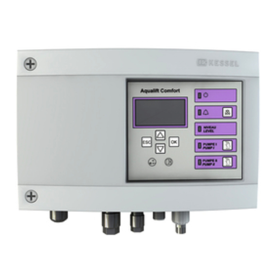
Spannungsführende Teile! Das Gehäuse des Schaltgeräts darf nur von einer Elektrofachkraft geöffnet werden! Die Tätigkeiten am Schaltgerät sind auf: den Tausch der Batterien, das Anschließen nach Einbauanleitung und Anschlussplan beschränkt. Alle darüber hinausgehenden Arbeiten dürfen lediglich durch den KESSEL-Kundendienst oder einen Servicepartner der KESSEL AG durchgeführt werden. WARNUNG Spannungsführende Teile Bei Tätigkeiten an elektrischen Leitungen und Anschlüssen Folgendes beachten. - Page 5 Produktbeschreibung Display Typenschild Anschlüsse Netzanschlussleitung Power-LED Taste Pumpe 1 Alarm-LED LED Pumpe 1 Taste Alarm quittieren Taste Pumpe 2 LED Niveauüberschreitung LED Pumpe 2 Pfeiltasten, OK, ESC 010-910_06 5 / 120...
- Page 6 Bestimmungsgemäße Verwendung Das Schaltgerät stellt die Steuerung einer Hebeanlage oder Pumpstation für Abwasser dar. Als Niveauerfassung können Drucksensoren, Schwimmerschalter oder Sonden verwendet werden. Ist das Schaltniveau erreicht, wird das Abpumpen akti- viert. Ist das Niveau entsprechend abgesunken, wird das Abpumpen selbsttätig beendet. Alle nicht vom Hersteller ausdrücklich und schriftlich autorisierten: Um- oder Anbauten Verwendungen von nicht originalen Ersatzteilen...
-
Page 7: Technische Daten
Technische Daten Ausführung Mono Maximale Leistung (kW) am 1,6 KW 2x 1,6 KW Schaltausgang (bei cos φ = 1) Nennstrombereich je nach Pumpe Strombereich 1-10 A 2x 1-10 A Gewicht 1,2 kg 1,4 kg Abmessungen (LxBxT), mm 210x200x75 295x200x75 Betriebsspannung 230V / 50Hz Leistung, Standby 3,5 W... -
Page 8: Montage
Drehmoment beachten! vormontierte oder beigelegte Kabelverschraubungen zur Kabeldurchführung (z. B. M16). Die Aderenden müssen hier bis zu den Anschlussklemmen auf der Platine durch- geführt werden. KESSEL 230V Schaltgeräte werden generell mit stecker- fertig vormontierter Netzleitung (Schukostecker) ausgelie- fert. Leitungsart A Kabelverschraubung Netz B Stecker (groß) - Page 9 Pumpe(n) anschließen WARNUNG Gefahr durch elektrischen Strom bei unbefugtem Demontieren eines Steckers während des Betriebs (z.B. durch Kinder). Die Befestigungsmutter des Steckers muss so fest angezogen werden, dass Kinder sie nicht entfernen können. Kabel mit Stecker passend kürzen und/oder verlängern. Zur Verlängerung (max.
- Page 10 Standardkonfiguration von Sonden Die Standardkonfiguration von KESSEL-Hebeanlagen ist ein Drucksensor (Tauchrohr oder Tauchglocke). Ein optischer Sensor als Alarmsonde liegt entweder bei oder kann auf den bereits vormontierten Anschluss montiert werden. Drucksensor Soll ein Drucksensor zur Ermittlung des Füllstandes verwen- det werden, diesen wie folgt anschließen.
- Page 11 Die von der Standardkonfiguration abweichenden Sensoren können für besondere Anwendungen (z. B. beengte Platz- verhältnisse oder besondere Medien) verwendet werden. In KESSEL-Anlagen dürfen nur Sensoren montiert wer- den, die von KESSEL zur Nachrüstung ausgewiesen wur- den. Außenanschluss tauschen/nachrüsten VORSICHT Das Anschließen von elektrischen Leitungen inner- halb des Schaltgerätes ist ausschließlich Elektrof-...
- Page 12 Schwimmerschalter Mono/Duo Prüfen, ob eine Mono oder Duo-Anlage vorliegt. Niveau für EIN 1, ggf. EIN 2 (Duo) und AUS definieren. KESSEL empfiehlt grundsätzlich zu den oben genannten ein Alarmniveau auszuführen. Position Klemmenbelegung Alarmniveau EIN 2 (nur Duo) EIN 1 Abb. 1: Schwimmerschalter Duo Abb.
- Page 13 USB-Anschluss herausführen Damit der USB-Anschluss auf der Platine ohne ein Öffnen des Gehäuses zugänglich wird, kann eine USB-Gehäusebuchse mit Kabel und Stecker zum Einbau in das Gehäuse des Schaltgeräts bei KESSEL bestellt werden (Art.-Nr. 28785). Diverses Zubehör - Schaltgeräte Fernsignalgeber Art.-Nr. 20162 Warnleuchte Art.-Nr.
-
Page 14: Inbetriebnahme
Inbetriebnahme Folgende Zusatzfunktionen führt das Schaltgerät selbsttätig aus: Überprüfung der Batteriespannung Das Schaltgerät prüft 2x täglich die Batteriespannung und meldet einen Batteriefehler (Potentialfreier Kontakt "Störung"), wenn die Spannung ein bestimmten Wert unterschreitet. Am Schaltgerät erscheinen alle 20 Sekunden optische und akkusti- sche Warnsignale. - Page 15 Alarm quittieren Das Schaltgerät zeigt (Alarm-)Meldungen wie folgt an: die Alarm-LED blinkt rot, eine Fehlermeldung erscheint im Display, ein akustischer Signalton ertönt. Taste Alarm quitteren 3 Sekunden betätigen. Ist die Fehlerursache behoben, verstummt der akustische Signalton und die LED hört auf zu blinken. Ein kurzes Betätigen der Taste Alarm schaltet den Alarmton aus, erhält jedoch die Fehlermeldung im Display und als Blinkmuster.
- Page 16 Menütexte 230V Systeminfo nur bei eingestecktem USB-Stick... Daten auslesen Software Update Parameter auslesen Informationen Betriebsstunden 1.1.1 Gesamtlaufzeit 0 - 999,999,9 1.1.2 Laufzeit Pumpe 1 0 - 999,999,9 1.1.3 Schaltspiele Pumpe 1 0 - 999,999,9 1.1.4 Netzausfall 0 - 999,999,9 1.1.5 Energieverbrauch 0,0 - 999,999,9 1.1.6...
- Page 17 Wartungsintervall 2.6.1 Gewerblich 3 Monate 2.6.2 Gewerblich 6 Monate 2.6.3 Privat 12 Monate 2.6.4 Manuelle Wartung 2.6.5 kein Wartungsintervall Kalibrierung Einstellungen Parameter 3.1.1 Einschaltverzögerung 0 - 99 3.1.2 Nachlaufzeit 0 - 99 3.1.3 Max. Strom 0 - 25 3.1.4 Min. Strom 0 - 25 3.1.5 Grenzlaufzahl...
- Page 18 3.4.20 Sonder-Pumpstation (Aqua- pump) Sensorkonfiguration 3.5.1 Drucksensor+Optische-Sonde 3.5.2 Drucksensor+Leitfähig- keit-Sonde 3.5.3 Drucksensor+Alarmschwimmer 3.5.4 Drucksensor+Lufteinperlung 3.5.5 Drucksensor+Lufteinperlung+ Alarmschwimmer 3.5.6 Drucksensor+Lufteinperlung+ optische Sonde 3.5.7 Schwimmer 3.5.8 Schwimmer ohne Aus-Niveau 3.5.9 Pegelsonde 3.5.10 Pegelsonde + Alarmschwimmer 3.5.11 Leitfähtigkeit-Sonde 3.5.12 Drucksensor 3.6. Kommunikation 3.6.1 Stationsname 3.6.2 Eigene Nummer...
- Page 19 Softwareupdate durchführen |Datenübertragung| Das Menü ist nur zugänglich, wenn ein Datenträger eingefügt wurde. Die "ESC"-Taste öff- |Datenübertragung| net/schließt das Menü Sicherstellen, dass ein Datenträger mit passender Systemdatei (z. B. KES6N_422-305.bin) eingefügt wurde. |0.1 Software update| Im Menü den Punkt auswählen. Periodisches Passwort (über Kundendienst zu beziehen - nur wenige Tage gültig!) eingeben.
-
Page 20: Wartung
Wartung Wartungstermin einstellen Der Wartungstermin wird über das Menü 2, Punkt 2.4 eingestellt. Folgen Sie dem Bildschirmdialog (zur Bedienung siehe "Abb. 3: Navigieren im Menü", Seite 14 ). Selbstdiagnosesystem (SDS) Das Selbstdiagnosesystem prüft automatisch (Intervall einstellbar) nachstehend beschriebene Anlagenfunktionen. Diese Einstellungen werden über das Menü... - Page 21 Dear Customer, As a premium manufacturer of innovative products for draining technology, KESSEL offers integrated system solutions and customer-oriented service. In doing so, we set the highest quality standards and focus firmly on sustainability - not only with the manufacturing of our products, but also with regard to their long-term operation and we strive to ensure that you and your property are protected over the long term.
-
Page 22: Notes On This Manual
Notes on this manual The following conventions make it easier to navigate the manual: Symbol Explanation See Figure 1 Position number 5 from the adjacent figure Action step in figure Check whether manual operation has been Prerequisite for action activated. Press OK. -
Page 23: Safety
Work on the control unit is restricted to: replacing the batteries, connection in accordance with the installation instructions and connection diagram. All work extending beyond this may only be carried out by the KESSEL customer service or a service partner of KESSEL AG WARNING Live parts Heed the following points when working on electrical cables and connections. - Page 24 Product description Display Type plate Connections Mains cable Power-LED Button, Pump 1 Alarm LED LED Pump 1 Button, acknowledge alarm Button, Pump 2 LED level exceedance LED Pump 2 Arrow buttons, OK, ESC 24 / 120 010-910...
- Page 25 Intended use The control unit represents the control of a lifting station or a pumping station for wastewater. Pressure sensors, float switches or probes can be used for level measurement. When the switching level has been reached, the pump-off function is activated.
-
Page 26: Technical Data
Technical data Version Mono Maximum power (kW) at the 1.6 kW 2x 1.6 kW switch output (if cos φ = 1) Nominal current range depending on the pump Current range 1-10 A 2x 1-10 A Weight 1.2 kg 1.4 kg Dimensions (LxWxD), mm 210x200x75 295x200x75... -
Page 27: Installation
Hang the control unit on the fastening screws and press downwards gently. (1) Sensor variants KESSEL control units are preconfigured for standard assign- ments, but also allow numerous accessories to be retrofitted and/or the installation of, for example, application-specific sensor configurations or communication interfaces. - Page 28 Connecting the pump(s) WARNUNG Electric shock hazard caused by unauthorised dis- mantling of a connector during operation (e.g. by children). The mounting nut of the connector must be tight- ened sufficiently so that it cannot be removed by children. Shorten and/or lengthen cable with plug to fit. To lengthen (max.
- Page 29 Standard configuration of probes The standard configuration of KESSEL lifting stations is a pressure sensor (immersion pipe or submersible pressure switch). An optical sensor for use as an alarm probe is either enclosed or can be mounted on the already preassembled connection.
- Page 30 Wire colour Name on PCB Terminal colour (-)Black blue not occupied Probe white (+)Red black Use KESSEL junction box (art. no. 28799) to lengthen the connection cable of the level sensor. 30 / 120 010-910...
- Page 31 Float switch, Mono/Duo Check whether the system is a Mono or a Duo system. Define level for ON 1, if applicable, ON 2 (Duo) and OFF. KESSEL recommends providing an alarm level for the items named above. Position Terminal assignment...
- Page 32 To ensure that the USB connection on the printed board can be accessed without opening the housing, a USB housing socket with cable and connector for installation in the housing of the control unit can be ordered from KESSEL (art. no.
-
Page 33: Commissioning
Commissioning The control unit performs the following additional functions automatically: Checking the battery voltage The control unit checks the battery voltage 2x daily and signals a battery error (potential-free contact “fault”) if the voltage falls below a certain level. Optical and acoustic warning signals appear on the control unit every 20 seconds. SDS Self diagnosis system The control unit has an automatic self-check, which performs a functional check of the connected components automatically. - Page 34 Acknowledge alarm The control unit displays (alarm) messages as follows: the alarm LED flashes red, an error message appears in the display, an acoustic signal sounds. Press the Alarm button for 3 seconds to acknowledge. If the cause of the error has been corrected, the acoustic signal falls silent and the LED stops flashing.
- Page 35 Current measured values 1.5.1 Mains power 0 - 99.9 1.5.2 Battery voltage 0 - 99.9 1.5.3 Level 0 - 5000 1.5.4 Temperature ° C 1.6. Parameters 1.6.1 On delay 0-99 1.6.2 Post run time 0-99 Password: 1000 1.6.3 Max. current 0 - 25.0 1.6.4 Min.
- Page 36 3.1.11 ON 1 - level 0 - 5000 3.1.12 OFF 1 - level 0 - 5000 3.1.13 Alarm level 0 - 5000 3.1.14 ON 2 - level 0 - 5000 3.1.15 OFF 2 - level 0 - 5000 Profile memory 3.2.1 Load parameters 3.2.2...
- Page 37 3.6. Communication 3.6.1 Station name 3.6.2 Own number 3.6.3 Modem type 3.6.4 3.6.5 SMS centre 3.6.6 SMS destination 1 3.6.7 SMS destination 2 3.6.8 SMS destination 3 3.6.9 Status 3.7. Language 3.10.1 Deutsch 3.10.2 English 3.10.3 [...] 3.8. Reset 010-910 37 / 120...
- Page 38 Updating the software |Data exchange| menu is only accessible if a data carrier has been inserted. The "ESC” key opens/closes the Data exchange| menu. Make sure that a data carrier with suitable system file (e.g. KES6N_422-305.bin) has been inserted. |0.1 Software update| In the menu, select the item.
-
Page 39: Maintenance
Maintenance Setting maintenance date The maintenance date is set via Menu 2, Item 2.4. Follow the screen dialogue (for details of operation, seesee "Fig. 3: Navi- gating in the menu", page 33 ). Self-diagnosis system (SDS) The self-diagnosis system checks the described system functions automatically (interval adjustable). These settings are made via Menu 3.1.9 (see "Menu texts Aqualift 230V"). - Page 40 Chère cliente, cher client, En qualité de producteur de pointe de produits novateurs dans le domaine de la technique d’assainissement, KESSEL pro- pose des réponses systématiques globales et un service orienté aux besoins de la clientèle. Nous misons simultanément sur les normes de qualité les plus élevées et une durabilité conséquente – non seulement lors de la fabrication de nos pro- duits, mais également pour leur utilisation à...
-
Page 41: Informations Spécifiques Aux Présentes Instructions
Informations spécifiques aux présentes instructions Les conventions de représentation suivantes facilitent l’orientation : Représentation Explication voir figure 1 Numéro de repère 5 de la figure ci-contre Action de la figure Vérifier si le mode manuel a été activé. Condition de réalisation de l’action Valider <OK>. -
Page 42: Sécurité
Tous les travaux dépassant ce cadre sont réservés au domaine de compétence du service après-vente KESSEL ou d’un partenaire de service après-vente de KESSEL AG AVERTISSEMENT Pièces sous tension... - Page 43 Description du produit Écran Plaque signalétique Raccords Câble d'alimentation Diode de puissance Touche pompe 1 Diode d'alarme Diode pompe 1 Touche acquittement de l'alarme Touche pompe 2 Diode de dépassement du niveau Diode pompe 2 Flèches, OK, ESC 010-910 43 / 120...
- Page 44 Utilisation conforme à l'usage prévu Le gestionnaire reproduit la commande d’un poste de relevage pour eaux usées. La détection du niveau est possible à l’aide de capteurs de pression, d’interrupteurs à flotteur ou de sondes. Le pompage est activé dès l'atteinte du niveau de commu- tation.
-
Page 45: Caractéristiques Techniques
Caractéristiques techniques Modèle Mono Puissance maximale (kW) à la sor- 1,6 KW 2x 1,6 KW tie de commutation (pour cos φ = 1) Plage de courant nominal en fonction de la pompe Plage de courant 1-10 A 2x 1-10 A Poids 1,2 kg 1,4 kg... -
Page 46: Montage
(par ex. M16). Les extrémités des conducteurs doivent être dirigées jusqu’aux bornes de connexion sur la platine. Les gestionnaires 230 V de KESSEL sont généralement fournis avec un câble secteur prémonté et prêt au raccor- dement (fiche à contact de protection). - Page 47 Raccordement de la/des pompe(s) WARNUNG Risque lié à la tension électrique en cas de démon- tage inopiné d'un connecteur pendant le service (p. ex. par des enfants). Serrer l'écrou de fixation du connecteur de sorte qu'il ne puisse pas être desserré par un enfant. Raccourcir et/ou rallonger le câble avec le connecteur de manière appropriée.
- Page 48 Configuration standard des sondes Un capteur de pression (tube plongeur ou cloche) repré- sente la configuration standard des postes de relevage KESSEL. Un capteur optique utilisé comme sonde d'alarme est inclus ou peut être monté sur le raccord déjà prémonté. Capteur de pression S’il est prévu d’utiliser un capteur de pression pour détermi-...
- Page 49 Dés. sur la pla- Couleur de la conducteur tine borne (-)Noir Bleu libre Probe Blanc (+)Rouge noir Utiliser la boîte à bornes KESSEL (réf. 28799) pour ral- longer le câble de raccordement de la sonde de niveau. 010-910 49 / 120...
- Page 50 Interrupteur à flotteur Mono/Duo Vérifier s'il s'agit d’un poste Mono ou Duo. Définir le niveau pour MARCHE 1, éventuellement pour MARCHE 2 (Duo) et pour ARRÊT. KESSEL recommande d'avoir également un niveau d'alarme. Position Affectation des bornes Niveau d’alarme MARCHE 2 (Duo unique- ment) Fig.
- Page 51 Afin que le port USB situé sur la platine soit aussi accessible sans l'ouverture du boîtier, il est possible de commander un boîtier à douille USB, équipé d'un câble et d'un connecteur, à intégrer dans le boîtier du gestionnaire chez KESSEL (réf.
-
Page 52: Mise En Service
Mise en service Le gestionnaire exécute les fonctions supplémentaires suivantes de manière automatique : Contrôle de la tension de la batterie Le gestionnaire vérifie la tension de la batterie 2 fois par jour et signale une erreur de la batterie (contact sec « dysfonc- tionnement ») si la tension descend en-dessous d'un certain niveau. - Page 53 Acquittement de l'alarme Le gestionnaire indique les messages (d'alarme) comme suit : la diode d'alarme clignote en rouge, un message d'erreur apparaît à l’écran, un signal acoustique retentit. Appuyer sur la touche Acquitter l’alarme pendant 3 secondes. Une fois la cause de l'erreur éliminée, le signal sonore s'arrête et la diode cesse de clignoter.
- Page 54 1.1.7 Cycles de commutation de la 0 à 999,999,9 pompe 2 Journal d'exploitation Type de commande Date de maintenance 1.4.1 Maintenance précédente mm:hh - jj.mm.aa 1.4.2 Maintenance suivante mm:hh - jj.mm.aa Valeurs actuellement mesu- 1.5.1 Courant de réseau 0 à 99,9 rées 1.5.2 Tension de la batterie...
- Page 55 Configurations Paramètres 3.1.1 Temporisation de mise en cir- 0 à 99 cuit 3.1.2 Durée de fonctionnement par 0 à 99 inertie 3.1.3 Courant max. 0 - 25 3.1.4 Courant min. 0 - 25 3.1.5 Nombre limite de mises en 1-99 marche 3.1.6 Durée limite de marche...
- Page 56 3.5.2 Capteur de pression + sonde de conductivité 3.5.3 Capteur de pression + interrup- teur à flotteur d'alarme 3.5.4 Capteur de pression + barbo- tage à l'air 3.5.5 Capteur de pression + barbo- tage à l'air + interrupteur à flot- teur d'alarme 3.5.6 Capteur de pression + barbo-...
- Page 57 Effectuer la mise à jour du logiciel |Transmission de données| Le menu n’est accessible que si un support de données a été inséré. La touche |Transmission de données| « ESC » ouvre/ferme le menu S'assurer qu'un support de données contenant un fichier système approprié (par ex. KES6N_422-305.bin) a été inséré. |0.1 Mise à...
-
Page 58: Maintenance
Maintenance Réglage de la date de maintenance La date de maintenance est définie via le menu 2, point 2.4. Suivez le dialogue affiché à l'écran (pour le fonctionnement voircf. "Fig. 3: Navigation dans le menu", page 52 ). Système d'autodiagnostic (SDS) Le système d'autodiagnostic procède à... - Page 59 Cara cliente, caro cliente, in qualità di produttore premium di prodotti innovativi per la tecnica di drenaggio, KESSEL offre soluzioni di sistema integrate e un servizio orientato al cliente. Puntiamo sui massimi standard qualitativi e ci impegniamo coerentemente per la sosteni- bilità...
-
Page 60: Indicazioni Sulle Presenti Istruzioni
Indicazioni sulle presenti istruzioni Le seguenti convenzioni illustrative semplificano l’orientamento: Simbolo Spiegazione vedere figura 1 Posizione numero 5 della figura accanto Passaggio procedurale nella figura Controllare se il funzionamento manuale è Presupposti per l’azione stato attivato. Premere OK. Passaggio procedurale L’impianto è... -
Page 61: Sicurezza
Tutti i lavori diversi da quelli elencati devono essere eseguiti esclusivamente dal servizio clienti KESSEL o da un partner di assistenza della KESSEL AG... - Page 62 Descrizione del prodotto Display Targhetta Collegamenti Cavo di alimentazione LED di alimentazione Tasto pompa 1 LED di allarme LED Pompa 1 Tasto conferma allarme Tasto pompa 2 LED superamento del livello LED Pompa 2 Tasti-freccia, OK, ESC 62 / 120 010-910...
- Page 63 Uso conforme alla destinazione La centralina costituisce il comando di un impianto di sollevamento o di una stazione di pompaggio per le acque di scarico. Per la rilevazione del livello è possibile utilizzare sensori di pressione, interruttori a galleggiante o sonde. Al raggiungimento del livello di commutazione, verrà...
-
Page 64: Dati Tecnici
Dati tecnici Variante Mono Potenza massima (kW) all’uscita 1,6 kW 2 x 1,6 kW di commutazione (con cos φ = 1) Gamma di corrente nominale a seconda della pompa Gamma di corrente 1-10 A 2 x 1-10 A Peso 1,2 kg 1,4 kg Misure (Lu x La x Pr), mm 210x200x75... -
Page 65: Montaggio
(ad esempio M16). Le estremità dei fili, in questo caso, devono essere condotte fino ai morsetti di collega- mento sulla scheda. Le centraline da 230 V KESSEL vengono fornite gene- ralmente con il cavo di rete premontato e pronto per l’uti- lizzo (con spina Schuko). - Page 66 Collegamento della pompa (delle pompe) WARNUNG Pericolo causato dalla corrente elettrica in caso di smontaggio non autorizzato di un connettore durante il funzionamento (ad esempio da parte di bambini). Il dado di fissaggio del connettore deve essere serrato saldamente, in modo da non poter essere rimosso dai bambini.
- Page 67 Configurazione standard delle sonde La configurazione standard degli impianti di sollevamento prevede un sensore di pressione (campana ad immersione o tubo ad immersione). Un sensore ottico quale sonda di allarme è fornito in dotazione o è montabile al collegamento premontato. Sensore di pressione Se dovesse essere impiegato un sensore di pressione per la determinazione del livello di riempimento, questo andrà...
- Page 68 Colore filo Denominazione Colore morsetto sulla scheda (-)Nero Non assegnato Probe Bianco (+)Rosso Nero In caso di prolungamento del cavo di collegamento della sonda di livello, usare la scatola di derivazione KESSEL (codice articolo 28799). 68 / 120 010-910...
- Page 69 Controllare se l’impianto è di tipo Mono o Duo. Definire il livello per ON 1, eventualmente ON 2 (Duo) e OFF. KESSEL consiglia in linea di massima di prevedere un livello d’allarme oltre ai livelli indicati sopra. Voce Assegnazione dei mor- setti Livello d’allarme...
- Page 70 Per fare in modo che il collegamento USB presente sul circuito stampato sia accessibile senza dover aprire l’alloggiamento è possibile ordinare presso KESSEL una presa USB per l’alloggiamento con cavo e connettore per l’installazione nell’allog- giamento della centralina (codice articolo 28785).
- Page 71 010-910 71 / 120...
-
Page 72: Messa In Funzione
Messa in funzione La centralina svolge autonomamente le funzioni supplementari seguenti: Controllo della tensione della batteria La centralina controlla due volte al giorno la tensione della batteria e segnala un errore della batteria (contatto a potenziale zero “Disturbo”) se la tensione scende al di sotto di un determinato livello. Sulla centralina compaiono ogni 20 secondi dei segnali di avvertimento ottici e acustici. - Page 73 Conferma dell’allarme La centralina mostra i messaggi (di allarme) come segue: il LED d’allarme lampeggia in rosso, un messaggio di errore compare sul display, viene emesso un segnale acustico. Azionare per 3 secondi il tasto di conferma dell’allarme. Una volta eliminata la causa dell’allarme, il segnale acu- stico cessa e il LED smette di lampeggiare.
- Page 74 Diario d’esercizio Tipo di comando Data di manutenzione 1.4.1 Ultima manutenzione mm:hh - gg.mm.aa 1.4.2 Prossima manutenzione mm:hh - gg.mm.aa Valori di lettura attuali 1.5.1 Corrente di rete elettrica 0 - 99,9 1.5.2 Tensione della batteria 0 - 99,9 1.5.3 Livello 0 - 5.000 1.5.4...
- Page 75 3.1.3 Corrente massima 0 - 25 3.1.4 Corrente minima 0 - 25 3.1.5 Numero max di accensioni 1-99 3.1.6 Tempo max di funzionamento minuti 0 - 999 3.1.7 Offset gorgogliamento dell’aria 0 - 999 3.1.8 Altezza tubo di ristagno 0 - 5.000 3.1.9 Sistema di auto-diagnostica 0 - 180...
- Page 76 3.5.4 Sensore di pressione + gorgo- gliamento dell’aria 3.5.5 Sensore di pressione + gor- gogliamento dell’aria + galleg- giante d’allarme 3.5.6 Sensore di pressione + gor- gogliamento dell’aria + sonda ottica 3.5.7 Interruttore a galleggiante 3.5.8 Interruttore a galleggiante senza livello OFF 3.5.9 Sonda idrostatica 3.5.10...
- Page 77 Esecuzione dell’aggiornamento del software |Trasferimento dati| Il menu è accessibile solo se è stato aggiunto un supporto di memoria. Il tasto “ESC” apre/ |Trasferimento dati| chiude il menu Accertare che sia stato aggiunto un supporto di memoria con un file system adeguato (ad esempio KES6N_422-305.bin). |0.1 Aggiornamento software| Nel menu, selezionare il punto Immettere la password periodica (reperibile presso il servizio clienti –...
-
Page 78: Manutenzione
Manutenzione Impostazione della scadenza di manutenzione La scadenza di manutenzione viene impostata tramite il menu 2, punto 2.4. Seguire il dialogo sullo schermo (per il comando vedere vd. "fig. 3: Navigazione nel menu", pagina 72). Sistema di auto-diagnostica (SDS) Il sistema di auto-diagnostica controlla automaticamente (intervallo regolabile) le funzioni dell’impianto descritte di seguito. Queste impostazioni vengono effettuate tramite il menu 3.1.9 (vd. - Page 79 Beste klant, Als premium fabrikant van innovatieve producten voor de afwateringstechniek biedt KESSEL totale systeemoplossingen en klantgerichte service. Wij stellen hierbij maximale kwaliteitsnormen en zetten consequent in op duurzaamheid, niet alleen bij de productie van onze producten, maar ook met het oog op hun langdurige gebruik zetten wij ons in voor een permanente bescherming van u en uw eigendom.
-
Page 80: Informatie Over Deze Handleiding
Informatie over deze handleiding De volgende weergaveconventies maken de oriëntatie eenvoudiger: Afbeelding Uitleg zie afbeelding 1 Positienummer 5 van nevenstaande afbeelding Handeling op de afbeelding … Controleren of de handmatige bediening is Voorwaarde voor de handeling ingeschakeld. Op OK drukken. Werkstap De installatie is bedrijfsklaar. -
Page 81: Veiligheid
De activiteiten bij de besturingskast zijn tot: het vervangen van de batterijen, het aansluiten volgens de inbouwhandleiding en het aansluitschema beperkt. Alle verdergaande werkzaamheden mogen enkel door de KESSEL klantenservice of een servicepartner van KESSEL AG worden uitgevoerd WAARSCHUWING Spanningvoerende delen Bij werkzaamheden aan de elektrische bekabeling en aansluitingen het onderstaande in acht nemen. - Page 82 Productomschrijving Display Typeplaatje Aansluitingen Netaansluitkabel Power-LED Toets pomp 1 Alarm-LED LED pomp 1 Toets alarm resetten Toets pomp 2 LED niveau-overschrijding LED pomp 2 Pijltoetsen, OK, ESC 82 / 120 010-910...
- Page 83 Reglementair gebruik De besturingskast vormt de besturing van een opvoerinstallatie of pompstation voor afvalwater. Als niveaudetectie kunnen druksensoren, vlotterschakelaars of sondes worden gebruikt. Als het schakelniveau is bereikt, wordt het wegpompen geacti- veerd. Als het peil navenant is gedaald, wordt het wegpompen automatisch beëindigd. Alle niet expliciet en schriftelijk door de fabrikant toegestane: om- of aanbouw gebruik van niet-originele onderdelen...
-
Page 84: Technische Gegevens
Technische gegevens Uitvoering Mono Maximaal vermogen (kW) bij uit- 1,6 KW 2x 1,6 KW gang schakelaar (bij cos. φ = 1) Nominaal stroombereik afhankelijk van de pomp Stroombereik 1-10 A 2x 1-10 A Gewicht 1,2 kg 1,4 kg Afmetingen (lxbxd), mm 210x200x75 295x200x75 Bedrijfsspanning... -
Page 85: Monteren
(bijv. M16). De draadeinden moeten worden doorgevoerd naar de aansluitklemmen op de printplaat. KESSEL 230V-besturingskasten worden over het alge- meen geleverd met een aansluitklare voorgemonteerde voedingskabel (Schuko-stekker). Type Leidingsoort... - Page 86 Pomp(en) aansluiten WARNUNG Gevaar door elektrische stroom bij ongeoorloofde demontage van een stekker tijdens bedrijf (bijv. door kinderen). De bevestigingsmoer van de stekker moet zo vastgedraaid worden dat kinderen deze niet kun- nen wegnemen. Verleng of verkort de kabel met stekker tot de juiste lengte.
- Page 87 Standaardconfiguratie van sondes De standaardconfiguratie van KESSEL-opvoerinstallaties is een druksensor (drukbuis of dompelklok). Een optische sen- sor als alarmsonde wordt meegeleverd of kan op de reeds voorgemonteerde aansluiting worden gemonteerd. Druksensor Als een druksensor moet worden gebruikt om het vulpeil vast te stellen, deze als volgt aansluiten.
- Page 88 De van de standaardconfiguratie afwijkende sensoren kunnen worden gebruikt voor speciale toepassingen (bijv. beperkte ruimte of speciale media). In KESSEL-installaties mogen alleen sensoren worden geïnstalleerd, die door KESSEL zijn goedgekeurd voor montage achteraf. Buitenaansluiting vervangen/achteraf monteren VOORZICHTIG Alleen elektriciens (in overeenstemming met de...
- Page 89 Vlotterschakelaar Mono/Duo Controleer of het een Mono of Duo is. Niveau voor AAN 1, evt. AAN 2 (Duo) en UIT definiëren. KESSEL raadt in principe aan om voor bovenstaande een alarmniveau in te stellen. Positie Klemmentoewijzing Alarmniveau AAN 2 (alleen Duo) AAN 1 Afb.
- Page 90 USB-aansluiting naar buiten voeren Om toegang te krijgen tot de op de printplaat aanwezige USB-aansluiting zonder de behuizing te openen, kan bij KESSEL een USB-behuizingsbus met kabel en stekker voor inbouw in de behuizing van de besturingskast (zie art.nr. 28785) worden besteld.
-
Page 91: Inbedrijfstelling
Inbedrijfstelling De volgende aanvullende functies worden automatisch door de besturingskast uitgevoerd: De batterijspanning controleren De besturingskast controleert twee keer per dag de batterijspanning en meldt een batterijfout (potentiaalvrij contact: “Sto- ring”) als de spanning onder een bepaald niveau komt. De besturingskast geeft elke twintig seconden optische en akoesti- sche waarschuwingssignalen. - Page 92 Alarm bevestigen De besturingskast geeft (alarm)meldingen als volgt aan: de alarmled knippert rood, er verschijnt een foutmelding op het scherm, er klinkt een signaaltoon. Toets Alarm bevestigen drie seconden indrukken. Als de oorzaak van de fout is verholpen, stopt de signaal- toon en stopt de led met knipperen.
- Page 93 Actuele meetwaarden 1.5.1 Netstroom 0 – 99,9 1.5.2 Batterijspanning 0 – 99,9 1.5.3 Niveau 0 – 5000 1.5.4 Temperatuur °C 1.6. Parameters 1.6.1 Inschakelvertraging 0 – 99 1.6.2 Nalooptijd 0 – 99 Wachtwoord: 1000 1.6.3 Max. stroom 0 – 25,0 1.6.4 Min.
- Page 94 3.1.9 ZDS-zelfdiagnosesysteem 0 – 180 3.1.10 Meetbereik peilsonde 0 – 5000 3.1.11 AAN 1 - niveau 0 – 5000 3.1.12 UIT 1 - niveau 0 – 5000 3.1.13 Alarmniveau 0 – 5000 3.1.14 AAN 2 - niveau 0 – 5000 3.1.15 UIT 2 - niveau 0 –...
- Page 95 3.5.11 Geleidbaarheidssonde 3.5.12 Druksensor 3.6. Communicatie 3.6.1 Stationsnaam 3.6.2 Eigen nummer 3.6.3 Modemtype 3.6.4 3.6.5 SMS-centrale 3.6.6 Sms-doel 1 3.6.7 Sms-doel 2 3.6.8 Sms-doel 3 3.6.9 Status 3.7. Taal 3.10.1 Deutsch 3.10.2 English 3.10.3 [...] 3.8. Resetten 010-910 95 / 120...
- Page 96 Software-update uitvoeren |Gegevensoverdracht| Het menu is alleen beschikbaar als er een gegevensdrager is geplaatst. De toets “ESC” |Gegevensoverdracht| opent/sluit het menu Zorg dat er een gegevensdrager met het juiste systeembestand (bijv. KES6N_422-305.bin) is geplaatst. |0.1 Software-update| Kies in het menu Voer het tijdelijke wachtwoord in (via de klantenservice te verkrijgen, maar een paar dagen geldig).
-
Page 97: Onderhoud
Onderhoud Onderhoudsdatum instellen De onderhoudsdatum wordt ingesteld via menu 2, punt 2.4. Volg de beeldschermdialoog (voor de bediening ziezie "Afb. 3: Navigeer in het menu", pagina 91 ). Zelfdiagnosesysteem (ZDS) Het zelfdiagnosesysteem controleert automatisch (interval instelbaar) de hieronder beschreven installatiefuncties. Deze instellingen worden gemaakt via menu 3.1.9 (zie "Menuteksten Aqualift 230V"). - Page 98 Szanowna Klientko, Szanowny Kliencie, jako producent najwyższej klasy innowacyjnych produktów z zakresu techniki odwadniania firma KESSEL oferuje komplek- sowe rozwiązania systemowe i serwis odpowiadający potrzebom klientów. Stawiamy sobie najwyższe standardy jakościowe i konsekwentnie stawiamy na trwałość – nie tylko podczas produkcji naszych urządzeń, lecz również w zakresie ich długo- trwałego użytkowania dbamy o to, by stale gwarantowane było bezpieczeństwo użytkownika i jego mienia.
-
Page 99: Wskazówki Dotyczące Niniejszej Instrukcji
Wskazówki dotyczące niniejszej instrukcji Poniższe formy oznaczeń ułatwiają orientację: Oznaczenie Objaśnienie Patrz rysunek 1 Numer pozycji 5 na rysunku obok Krok postępowania na rysunku Sprawdzić, czy aktywo- Warunek postępowania wana została obsługa ręczna. Nacisnąć przycisk OK. Krok postępowania Urządzenie jest gotowe do pracy. Wynik postępowania Odniesienie do rozdz. -
Page 100: Bezpieczeństwo
Prace przy urządzeniu sterującym ograniczają się do: wymiany baterii, podłączenia według instrukcji zabudowy i schematu połączeń. Wszelkie inne prace może wykonywać wyłącznie serwis klienta KESSEL lub partner serwisowy firmy KESSEL AG. OSTRZEŻENIE Elementy będące pod napięciem Podczas prac przy przewodach i przyłączach elektrycznych należy przestrzegać następujących wskazówek. - Page 101 Opis produktu Wyświetlacz Tabliczka znamionowa Przyłącza Przewód sieciowy Dioda LED zasilania Przycisk pompa 1 Dioda LED alarmu Dioda LED pompy 1 Przycisk do kasowania alarmu Przycisk pompa 2 Dioda LED przekroczenia poziomu Dioda LED pompy 2 Przyciski ze strzałkami, OK, ESC 010-910 101 / 120...
- Page 102 Zastosowanie zgodnie z przeznaczeniem Urządzenie sterujące przeznaczone jest do sterowania przepompownią ścieków. Jako urządzenie do wykrywania poziomu stosowane są czujniki ciśnienia, przełączniki pływakowe lub sondy. Gdy osiągnięty zostanie poziom przełączenia, rozpo- częte zostaje pompowanie. Gdy poziom ścieków odpowiednio spadnie, pompowanie zostaje samoczynnie zakończone. Wszystkie nieautoryzowane przez producenta wyraźnie i pisemnie: przebudowy lub dobudowy użycie nieoryginalnych części zamiennych...
-
Page 103: Dane Techniczne
Dane techniczne Wariant Mono Maksymalna moc (kW) na wyj- 1,6 kW 2x 1,6 kW ściu przełączającym (dla cos φ = 1) Zakres prądu znamionowego zależnie od pompy Zakres prądu 1-10 A 2x 1-10 A Ciężar 1,2 kg 1,4 kg Wymiary (dł x szer x gł), mm 210 x 200 x 75 295 x 200 x 75 Napięcie robocze... -
Page 104: Montaż
Zawiesić urządzenie sterujące na śrubach mocujących i lekko wcisnąć je w dół. (1) Warianty czujników Urządzenia sterujące KESSEL są wprawdzie wstępnie skon- figurowane do przyporządkowań standardowych, ale zezwa- lają na dodatkowe doposażenie w osprzęt i/lub instalację np. konfiguracji czujników lub złączy komunikacyjnych odpowia- dających indywidualnym potrzebom klienta. - Page 105 Podłączenie pomp(y) WARNUNG Niebezpieczeństwo porażenia prądem elektrycz- nym w przypadku nieuprawionego odłączenia wtyczki podczas eksploatacji (np. przez dzieci). Nakrętka mocująca wtyczki musi być tak mocno dociągnięta, aby dzieci nie mogły jej zdjąć. Skrócić lub przedłużyć kabel z wtyczką do odpowiedniej długości.
- Page 106 Konfiguracja standardowa sond Standardowa konfiguracja przepompowni KESSEL to czuj- nik ciśnienia (czujnik ciśnienia lub dzwon zanurzeniowy). Czujnik optyczny jako sonda alarmowa jest albo dołączony, albo można go zamontować na gotowym już, wstępnie zmontowanym przyłączu. Czujnik ciśnienia Jeżeli do wyznaczania stanu napełnienia używany ma być...
- Page 107 Indywidualna konfiguracja czujnika Czujników innych niż konfiguracja standardowa można uży- wać do zastosowań specjalnych (np. w przypadku wąskich pomieszczeń lub mediów specjalnych). W urządzeniach KESSEL wolno montować tylko czujniki podane przez firmę KESSEL do doposażenia. Wymiana lub doposażenie zewnętrznego przyłącza OSTRZEŻENIE Podłączenia przewodów elektrycznych w obrębie...
- Page 108 Przełącznik pływakowy w urządzeniach typu Mono/Duo Sprawdzić, czy urządzenie jest typu Mono lub Duo. Zdefiniować poziom dla WŁ. 1, ewentualnie WŁ. 2 (Duo) i WYŁ. Firma KESSEL zaleca zdefiniowanie zasadniczo poziomu alarmowego. Pozycja Obłożenie zacisków Poziom alarmu WŁ. 2 (tylko Duo) WŁ.
- Page 109 Zamontować modem TeleControl (nr art. 28792) według odpowiedniej instrukcji montażu 434-033. Wyprowadzenie portu USB Jeżeli port USB ma być dostępny bez konieczności otwarcia obudowy, można zamówić w firmie KESSEL gniazdo USB z kablem i wtyczką do zabudowy w obudowie urządzenia sterującego (nr art. 28785).
-
Page 110: Uruchomienie
Uruchomienie Urządzenie sterujące wykonuje samoczynnie następujące funkcje dodatkowe: Kontrola napięcia baterii Urządzenie sterujące sprawdza dwa razy dziennie napięcie baterii i zgłasza błąd baterii (kontakt bezpotencjałowy „Zakłóce- nie”), jeśli wartość napięcia spadnie poniżej określonego poziomu. Na urządzeniu sterującym generowane są co 20 sekund optyczne i akustyczne sygnały ostrzegawcze. - Page 111 Kasowanie alarmu Urządzenie sterujące wskazuje komunikaty (alarmowe) w następujący sposób: dioda LED alarmu miga na czerwono, na wyświetlaczu pojawia się komunikat o błędzie, rozbrzmiewa sygnał dźwiękowy. Naciskać na przycisk do kasowania alarmu przez 3 sekundy. Po usunięciu przyczyny błędu sygnał dźwiękowy zostaje wyłączony, a diody LED przestają...
- Page 112 Termin konserwacji 1.4.1 Ostatnia konserwacja mm:hh - dd.mm.rr 1.4.2 Następna konserwacja mm:hh - dd.mm.rr Aktualne wartości zmierzone 1.5.1 Prąd sieciowy 0 - 99,9 1.5.2 Napięcie baterii 0 - 99,9 1.5.3 Poziom 0 - 5000 1.5.4 temperatura °C 1.6. Parametry 1.6.1 Opóźnienie włączenia 0 - 99 1.6.2...
- Page 113 3.1.5 Maksymalna liczba biegów 1 - 99 3.1.6 Maksymalny czas pracy 0 - 999 3.1.7 Kompresor 0 - 999 3.1.8 Wysokość dzwonu spiętrzenio- 0 - 5000 wego 3.1.9 System samodiagnozy SDS 0 - 180 3.1.10 Zakres pomiaru elektrodowej 0 - 5000 sondy poziomu 3.1.11 Poziom WŁ.
- Page 114 3.5.5 Czujnik ciśnienia + kompre- sor + przełącznik pływakowy alarmu 3.5.6 Czujnik ciśnienia + kompresor + sonda optyczna 3.5.7 Przełącznik pływakowy 3.5.8 Przełącznik pływakowy bez funkcji poziom WYŁ. 3.5.9 Sonda hydrostatyczna 3.5.10 Sonda hydrostatyczna + prze- łącznik pływakowy alarmu 3.5.11 Sonda do pomiaru przewodno- ści 3.5.12...
- Page 115 Aktualizacja oprogramowania |Transmisja danych| Menu dostępne jest tylko wtedy, gdy włożony został nośnik danych. Naciśnięcie przycisku |Transmisja danych| ESC powoduje otwarcie lub zamknięcie menu Zapewnić, aby włożony został nośnik danych z pasującym plikiem systemowym (np. KES6N_422-305.bin). |0.1 Aktualizacja oprogramowania| Wybrać w menu punkt Wprowadzić...
-
Page 116: Konserwacja
Konserwacja Ustawianie terminu konserwacji Termin konserwacji można ustawić w menu 2, punkt 2.4. Postępować według dialogu na ekranie (odnośnie obsługi patrz patrz "rys. 3: Nawigacja po menu", strona 110). System samodiagnozy (SDS) System samodiagnozy automatycznie sprawdza (w ustawionych interwałach) niże opisane funkcje urządzenia. Tych usta- wień... - Page 118 118 / 120 010-910_06...
- Page 119 010-910_06 119 / 120...
- Page 120 Registrieren Sie Ihr Produkt online, um von einer schnelleren Hilfe zu profitieren! http://www.kessel.de/service/produktregistrierung.html KESSEL AG, Bahnhofstr. 31, 85101 Lenting, Deutschland...
Need help?
Do you have a question about the Comfort 230V Mono and is the answer not in the manual?
Questions and answers