Graco Therm-O-Flow 200 Instructions - Parts Manual
Warm melt
Hide thumbs
Also See for Therm-O-Flow 200:
- Instructions-parts list manual (118 pages) ,
- Instructions - parts manual (112 pages) ,
- Instructions manual (98 pages)
Table of Contents
Advertisement
Quick Links
Instructions - Parts
Therm-O-Flow
Warm Melt
For dispensing sealants, adhesives, and other medium to high viscosity fluids. For
professional use only.
Not approved for use in explosive atmospheres or hazardous (classified) locations.
See page 4 for model information, including maximum
working pressure and approvals.
Important Safety Instructions
Read all warnings and instructions in this
manual and related manuals before using
the equipment. Save these instructions.
®
3A8005A
EN
Advertisement
Table of Contents
Troubleshooting

Related Manuals for Graco Therm-O-Flow 200


Summary of Contents for Graco Therm-O-Flow 200
- Page 1 Instructions - Parts ® Therm-O-Flow Warm Melt 3A8005A For dispensing sealants, adhesives, and other medium to high viscosity fluids. For professional use only. Not approved for use in explosive atmospheres or hazardous (classified) locations. See page 4 for model information, including maximum working pressure and approvals.
-
Page 2: Table Of Contents
Contents Related Manuals ......3 Operation ....... . . 40 Models . -
Page 3: Related Manuals
California Proposition 65 ....151 Graco Standard Warranty ....152... -
Page 4: Models
Models Models Therm-O-Flow Warm Melt Check the identification plate (ID) on the back of the ram post near the Heat Control Box (S) for the seven-digit part number of the Therm-O-Flow Warm Melt. Use the following matrix to define the construction of the unit, based on the seven digits. -
Page 5: Therm-O-Flow Warm Melt Pressure
Models Therm-O-Flow Warm Melt Pressure Due to factors such as the dispensing system design, the material being pumped, and the flow rate, the dynamic pressure will not reach the rated working (stall) pressure of the system. Pump Working (Stall) Pressure Lower Size Air Motor Power Factor... -
Page 6: Heat Zones
Models Heat Zones Tandem System The following tables show how many heat zones are available on Therm-O-Flow Warm Melt systems. The tables show heat zones available for hoses or Standard Heat Control Box Ambient Pump and accessories used on single or tandem systems. The Platen number of heat zones depends on whether the system Heated Hose Zones... -
Page 7: Warnings
Warnings Warnings The following warnings are for the setup, use, grounding, maintenance, and repair of this equipment. The exclamation point symbol alerts you to a general warning and the hazard symbols refer to procedure-specific risks. When these symbols appear in the body of this manual or on warning labels, refer back to these Warnings. Product-specific hazard symbols and warnings not covered in this section may appear throughout the body of this manual where applicable. - Page 8 Warnings WARNING MOVING PARTS HAZARD Moving parts can pinch, cut or amputate fingers and other body parts. • Keep clear of moving parts. • Do not operate equipment with protective guards or covers removed. • Equipment can start without warning. Before checking, moving, or servicing equipment, follow the Pressure Relief Procedure and disconnect all power sources.
- Page 9 Warnings WARNING EQUIPMENT MISUSE HAZARD Misuse can cause death or serious injury. • Do not operate the unit when fatigued or under the influence of drugs or alcohol. • Do not exceed the maximum working pressure or temperature rating of the lowest rated system component.
-
Page 10: Component Identification
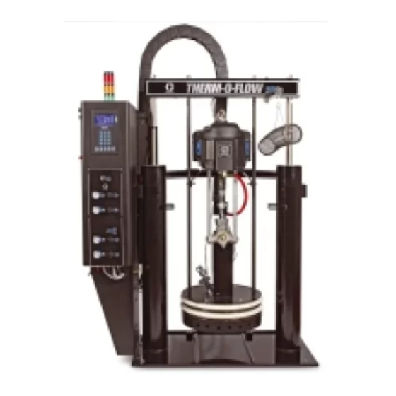
Component Identification Component Identification Single Therm-O-Flow Warm Melt D200 3 in. Dual Post, 200 Liter Platen Lift Locations . 1: Therm-O-Flow Warm Melt Key: Ram Assembly Heat Control Box Air Motor Disconnect Switch (see Power Disconnect on page 12) Displacement Pump *Pump Heater Platen (see F . -
Page 11: Tandem Therm-O-Flow Warm Melt
Component Identification Tandem Therm-O-Flow Warm Melt See Tandem Cable Kit, 26B339 on page 135. D200 3 in. Dual Post, 200 Liter Platen Unit A Unit B . 2: Tandem Therm-O-Flow Warm Melt Unit A: This Therm-O-Flow Warm Melt includes an ADM and is marked with the “A”... -
Page 12: Air Line Accessories
Component Identification Air Line Accessories See F . 1 on page 10. Air Line Drain Valve (M) Air Filter (N): Removes harmful dirt and moisture from compressed air supply. Bleed Type Air Shut Off Valve (P): Isolates air line accessories and Therm-O-Flow Warm Melt Supply System for servicing. -
Page 13: Integrated Air Controls
Component Identification Integrated Air Controls . 4. Integrated Air Controls AA Main Air Slider Valve AH Air Motor Slider Valve Turns air on and off to the entire system. When Turns air on and off to the air motor. When closed, closed, the valve relieves pressure downstream. -
Page 14: Platen (D) Component Identification
Component Identification Platen (D) Component Identification Heated Ambient Key: BA Plate BH Air Assist Body Check Valve BB Wiper BJ Wiper Plate (under wiper) BC Heater Cover BK O-ring Seal (not shown) BD Cap Screws BL Platen Valve Port BF Bleed Stick BM Platen Valve Cap BG Bleed Port 3A8005A... -
Page 15: Heat Control Box Connections
Component Identification Heat Control Box Connections Single Heat Module Expansion Heat Module Key: CA CAN Cable Connection Ports* On Unit A, this top port connects to the ADM. If using a CB PLC Input/Output Cord Grip tandem system, the top connection port on Unit A is CC Heated Hose/Accessory Connector connected to the top connection port on Unit B via the CAN CD Heated Pump Connection**... -
Page 16: Advanced Display Module (Adm)
Component Identification Advanced Display Module (ADM) Front and Rear Views . 7. ADM Component Identification Key: DA Startup/Shutdown DG Lock/Setup Starts up or shuts down the system. Toggles Toggles between Run screens and the Main Menu. between Active and Inactive system. DH Directional Keypad DB System Status Indicator LED Navigate within a screen or to a new screen. -
Page 17: Adm Display Details
ADM Display Details ADM Display Details Power Up Screen Screen Menu This screen appears when the ADM is powered up. The screen menu indicates the current active screen, which is highlighted. It also indicates the associated This screen remains on while the ADM runs through screens that are available by scrolling left and right. - Page 18 ADM Display Details Navigating the Screens Set Password There are two types of screens: You can set a password to protect access to some selections on the Main Menu screens. See Main Menu Run screens control operations and display system on page 21.
-
Page 19: Adm Led Status Descriptions
ADM Display Details ADM LED Status Descriptions Conditions Description System Status Green Solid Run Mode, System On Green Flashing Setup Mode, System On Yellow Solid Run Mode, System Off Yellow Flashing Setup Mode, System Off USB Status (CL) Green Flashing Data recording in progress Yellow Solid Downloading information to USB... -
Page 20: Adm Soft Keys
ADM Display Details ADM Soft Keys Icon Function Icon Function Turn heat zones on and off. Enter or exit editing mode for a particular screen. Place all heat zones into setback and Access the Schedule screens. out of setback. Reset Cycle Counter. Access the Heat Setup screens. -
Page 21: Main Menu
ADM Display Details Main Menu The Menu screens provide access to settings that help If you set a password, the menu will be displayed with to ensure the proper operation and maintenance of the red locks above the menu selections with parameters system. -
Page 22: Installation
Installation Installation Grounding The Therm-O-Flow Warm Melt includes the fully assembled Ram Assembly and Pump. This section describes how to install and set up the Therm-O-Flow Warm Melt and make all the necessary component connections. The equipment must be grounded to reduce the risk of static sparking and electric shock. -
Page 23: Power Requirements
Installation Power Requirements Connect Power Each Therm-O-Flow Warm Melt requires a dedicated circuit protected with a circuit breaker. 5 Gallon Heated Pump and Platen: All electrical wiring must be done by a qualified elec- Standard Heat Expansion trician and comply with all local codes and regula- Control Box Module Max tions. -
Page 24: Air Line Connections
Installation 8. Tighten the strain relief bushing (SR) around the electrical cord. 9. Replace the cover (452) on the Heat Control Box (S). Air Line Connections Refer to F . 1 on page 10 for a typical installation. Attach the Air Line (L) (not supplied) to the bottom of the Integrated Air Control (F) at the 3/4 in. -
Page 25: Attach Drum Stops
Installation Attach Drum Stops 2. Using the capscrews and lock washers, attach the drum stops to the Ram Assembly base. Therm-O-Flow Warm Melt systems are provided with drum stops in place to help position the drum on the D200 and D200s Base 55 gal (200 L) Ram Assembly (A). -
Page 26: Setup
Before starting, fill the Wet Cup (K) 1/3 full with Graco pressure the system is capable of attaining. All Throat Seal Liquid (TSL) or a compatible solvent. -
Page 27: Connect Heated Accessories
Setup Connect Heated Accessories If your application requires multiple heated accessories, connect heated hose electrical connectors to the Heat Control Box. Example Heated zones are used to connect a primary and secondary system to a heated block and a single dispense valve. -
Page 28: Fig
Setup Unit B Unit A Square Pump Heat Hose 2 Electrical Hose 1 Pump Heat Connector Heated Tandem Block Platen Heat Platen Heat Hose 3 Square Electrical Connector Circular Electrical Connector Circular Electrical Heated Connector Dispense Valve . 15 3A8005A... -
Page 29: Install Expansion Module
Setup Install Expansion Module The Therm-O-Flow Warm Melt comes standard with a Heat Control Box (S), which supports up to six heat zones in addition to the Pump and Platen heat zones. When the Expansion Module is added to the system, eight additional heat zones can be added, which increases the maximum current draw of the system. - Page 30 Setup 6. Disconnect the CAN cable from Bulkhead 2 (B2) on AMZ 1 in the Heat Control Box (S) and reconnect it to Bulkhead 1 (B1) on AMZ 2 in the Expansion Module. AMZ 1 . 20 8. Install the protective strip around the opening between the enclosures.
-
Page 31: System Setup Screen
Setup System Setup Screen 12. Connect the ground wires to the ground terminal (455) by loosening the nut (437) on the wiring harness. NOTICE To prevent damage to ADM buttons, do not press the buttons with sharp objects such as pens, plastic cards, or fingernails. -
Page 32: Heat Settings
Setup To run the Scheduler, select Scheduler from the drop The same applies to the Low Alarm and Low Deviation down list. This will enable the Scheduler feature. See settings. In the same example at 50 degrees with a Low page 49 for more information. - Page 33 Setup NOTE: To ensure accurate hose temperatures, be sure all heated hoses have their “zone type” set to “Hose.” If using an expansion module, Heat-A-E zone numbers for hoses are even numbers: 10, 12, 14, or 16. To setup the optional Schedule function, see Schedule, page 49.
-
Page 34: Advanced Setup
Setup Advanced Setup Tandem Heat Setup Screen 1 Read all of Heat Setup Screen 1 starting on page 32 before reading this section. Press on the ADM to navigate to the Main Menu The Heat Setup screens are the same for Single and screens. - Page 35 Setup 8. For the Password Timeout, enter the amount of time that can pass before the password is required. 9. Press the soft key to save your changes and exit editing mode. Advanced Setup Screen 2 Use the ADM Directional Keypad (DH) to navigate to Advanced Screen 2.
- Page 36 1. Press the soft key to enter editing mode. update the system software using a USB drive with the latest software and a Graco black token. The latest 2. USB downloads automatically begin when a USB software is provided on Help.graco.com.
-
Page 37: Hose Care Guidelines
Hose Care Guidelines Hose Care Guidelines Do not flex hose when cold. Fluids subjected to heat in confined spaces can create a rapid rise in pressure due to the thermal expansion. Over-pressurization can result in equip- ment rupture and serious injury. •... -
Page 38: Startup
Component Identification tory-test oil from the system. If necessary, check section starting on page 10. with Graco or the material supplier for a recom- mended solvent. Purge System 4. Before purging, be sure the entire system and waste pail are properly grounded. - Page 39 Startup 5. Lubricate the Platen wiper with grease or another NOTE: Loading the material at a lower pressure keeps lubricant compatible with the material being loaded. the Pump (C) from cavitating while there is no material in the Pump. 6. Place a full pail or drum of material on the Ram Assembly base and center it under the Platen (D), NOTE: For tandem units, only the inactive system can then remove the drum cover and smooth the...
-
Page 40: Operation
Operation Operation 1. Turn the Disconnect Switch (T) ON. The Graco logo will display until communication and initialization is complete. 2. Press the button. Verify the machine is in “Warm Up” state, and that the temperatures are increasing. Allow the system to reach the “Ready”... -
Page 41: Single Run Screen
Operation Single Run Screen 1. Heat On/Off: Turns the heat on and off on all active 9. PLC Lockout: Displays the PLC lockout status. zones. When the PLC is in control, the icon displayed is 2. Pump Enable ON/OFF: Energizes the Solenoid to . -
Page 42: Tandem Run Screen
Operation Tandem Run Screen 1. Heat On/Off: Turns the heat on and off on all active 9. PLC Lockout: Displays the PLC lockout status. zones. When the PLC is in control, the icon displayed is 2. Pump Enable ON/OFF: Energizes the Solenoid to . -
Page 43: Heat Run Screen
Operation Heat Run Screen When Heat is selected for a pump or accessory at the The Zone Heat Symbols on the right side of the screen System Setup screen, a Heat Run screen is available. correspond to the current type to which the zone is set. See System Setup Screen on page 31. - Page 44 Operation 1. Press the soft key to turn the heat zones on and off. 2. When the icon is showing, the user can put the system into setback by pressing the soft key. This places all of the zones displayed on the screen to setback and shows the setback temperature in the zone setpoint/setback temperature box.
-
Page 45: Events And Errors
Operation Events and Errors Events Log Screen Errors Log Screen Press the soft key on Main Menu screen 1 to Press the soft key on Main Menu screen 1 to access the Events log. access the Errors log. This screen shows the Date, Time, Event Code, and This screen shows the Date, Time, Error Code, and Description of all events that have occurred on the Description of all errors that have occurred on the... -
Page 46: Pressure Relief Procedure
Operation Pressure Relief Procedure 3. Set the Ram Director Valve (AC) to the neutral position. Follow the Pressure Relief Procedure whenever you see this symbol. This equipment stays pressurized until pressure is manually relieved. To help prevent serious injury from pressurized fluid, such as skin injection, splashing fluid and moving parts, follow the Pressure Relief Procedure when you stop spraying and before... -
Page 47: Stop Controls
Operation Stop Controls NOTE: If work needs to be performed on the Ram Assembly (A) portion, perform the following additional steps to relieve any trapped air in the inactive portion of Normal Stop Control the Ram Assembly. To stop all electrical and most pneumatic processes, 9. -
Page 48: Shutdown
Operation Air Motor and Pump Stop 1. Press to disable the heaters and Pump (C). To stop only the Air Motor (B) and Pump (C), close the The screen will toggle between “Pump Inactive” and Air Motor Slider Valve (AH). This is the preferred “Heat Inactive”. -
Page 49: Schedule
Operation Schedule Set Schedule Times Times are set using a 24-hour clock. Several on and off times can be set each day. Press the on the ADM from any run screen to go to the Main Menu Screens. Press the soft key on the ADM to go to the Sched- ule screen. -
Page 50: Maintenance
Maintenance Maintenance Press the soft key at Main Menu screen 2 to access the Maintenance screens. The Maintenance screens are the same for Single and Tandem systems, except Tandem systems will shown Unit B in the Menu Bar. Use the ADM’s Directional Keypad (DH) to navigate to Unit A or Unit B. -
Page 51: Diagnostics
Diagnostics Diagnostics Heat Diagnostics Screen Press the soft key at Main Menu screen 1 to access the Diagnostics screens. These screens display Use the ADM’s Directional Keypad (DH) to navigate to key parameters that are useful in troubleshooting the Heat Diagnostics Screen. This screen displays the issues. - Page 52 Diagnostics The Zone Heat Symbol on this screen corresponds to the current type to which the zone is set. Zone Heat Symbol Hose Valve Manifold Flowmeter Press Regulator Pump Platen The zone heat state is the circle with two numbers inside of it next to the zone heat symbol.
-
Page 53: Troubleshooting
Troubleshooting Troubleshooting Press the soft key to advance to a keyboard screen that allows you to search for an error by error code. Type in the error code, then press the soft key to advance to advance to the QR Code screen. REMOTE SYSTEM ACTIVATION HAZARD To avoid injury due to remote machine operation, perform the steps below before troubleshooting. -
Page 54: Troubleshoot Errors
Error Codes table on page 55. You can also the process. The advisory needs attention to prevent call Graco Technical Assistance or navigate to: more serious issues in the future. http://help.graco.com/en/therm-o-flow-products/therm-o -flow-warm-melt.html. -
Page 55: Error Codes
Troubleshooting Error Codes The last digit of the error code indicates which system component the error applies. The “#” (pound) character indicates the code applies to multiple system compo- There are three types of errors that can occur. Errors are indicated on the display as well as by the optional nents. - Page 56 Troubleshooting Error Location Type Error Name Error Description Cause Solution A1__ Alarm Low Current Heater current is below Fault heater Check heater resistance U_Z_ the minimum allowed element and resistance to value ground. Replace faulty heater A2__ Advisory Low Current Heater current is below Fault heater Check heater resistance...
- Page 57 Troubleshooting Error Location Type Error Name Error Description Cause Solution CAC_ Alarm Communicatio Communication lost No 24 VDC Reconnect or replace n Error U_ between ADM and power supply CAN cable connecting Heat Module to ADM AMZ and ADM. If CAN connection good, check 24V power supply wiring in side the heat box.
- Page 58 Troubleshooting Error Location Type Error Name Error Description Cause Solution CCG_ Gateway Alarm Fieldbus No communication The gateway Restore Comm. Error with the fieldbus lost communications. communication with the unit controller CCT_ Alarm Duplicate Multiple AMZ MZLP4s Two or more Turn dial on AMZ to an Module U_D_ using same module ID...
- Page 59 Troubleshooting Error Location Type Error Name Error Description Cause Solution EDT_ Record Heat at Unit Heat is at the Unit heat has No action necessary if Only Temperature desired zone successfully the desired temperature temperature reach the was reached. desired zone temperature EAW_ Record...
- Page 60 Troubleshooting Error Location Type Error Name Error Description Cause Solution L2P_ Pump Deviation Drum Low U_ Drum level is low Fluid level in Clear deviation and drum is low. return to normal pump Consider operation. replacing soon Drum level Verify level sensor is sensor is connected.
- Page 61 Troubleshooting Error Location Type Error Name Error Description Cause Solution T3__ Advisory High The zone temperature Element Defective RTD. Replace. Temperature has exceeded the continues to U_Z_ setpoint raise above the setpoint RTD not in See manual to find correct location correct location of RTD on element on element.
- Page 62 WSU0 Alarm USB configuration file Update software to the Configuration not detected congifuration latest available on Error file not loaded help.graco.com. or was deleted DAP_ Pump Alarm Pump Pump Runaway Pump is trying Adjust the drum empty Runaway U_ Detected...
- Page 63 Troubleshooting Error Location Type Error Name Error Description Cause Solution DDP_ Pump Deviation Pump Diving Pump Diving Detected Pump is trying Adjust the drum empty to feed level sensor to detect an material, no empty state. material to feed Ensure the ram director valve is in the down position and sufficient air is forcing the ram down.
- Page 64 Troubleshooting Error Location Type Error Name Error Description Cause Solution WKD_ Pump Alarm Fill Solenoid High Current detected Solenoid is Inspect for short in High Current on Fill solenoid drawing too harness. much current Inspect for a shorted solenoid cable/short to ground.
- Page 65 Troubleshooting Error Location Type Error Name Error Description Cause Solution ERP_ Pump Record Pump Unit was told to clear The unit No action necessary. Only Counter pump counter received a Cleared U_ command to clear pump counter ERD_ Pump Record Pump Drum Unit was told to clear The unit...
-
Page 66: Ram Assembly Troubleshooting
Troubleshooting Ram Assembly Troubleshooting Problem Cause Solution Closed main air valve or clogged air Open air valve; clear air line. Ram will not raise or lower. line, Not enough Ram air pressure. Increase Ram air pressure. Worn or damaged Ram piston. Replace piston. -
Page 67: Pump Troubleshooting
Troubleshooting Pump Troubleshooting See Pump manual for additional Pump troubleshooting information. See Related Manuals, page 3. Problem Cause Solution Rapid downstroke or upstroke (Pump Material not heated to proper Check and adjust temperature to cavitation). temperature. proper setpoint. Wait for Pump/Platen to heat up. -
Page 68: Heat Control Box Troubleshooting
Troubleshooting Heat Control Box Troubleshooting Problem Cause Solution System does not heat. Blown fuse. Replace fuse. Over-temperature switch tripped. Measure over-temperature switch resistance. It should read close to 0 ohms when at room temperature. If open, replace over-temperature switch. Cable to over-temperature switch is Check connection of cable to off or broken. -
Page 69: Check Resistance (Heated Systems)
Troubleshooting Check Resistance (Heated Systems) Check Heater and Sensor Resistance To reduce risk of injury or damage to equipment, conduct these electrical checks with the Disconnect Switch (T) OFF. NOTE: Instructions for checking sensor resistance applies to heated systems only. If an expansion module (26B238) is added, an additional eight sensors are available. - Page 70 Troubleshooting Table 2: Main Enclosure Sensors RTD Range RTD Pin Heater Element Heater Pin Port Zone Component (Ohms) Numbers Resistance (Ohms) Numbers Heated Hose G, K See hose manual See hose manual See accessory Heated Accessory 1 M, K See accessory manual manual Heated Hose G, K...
-
Page 71: Usb Data
® Windows Explorer. The event log maintains a record of the last 1,000 events and errors. Each event record contains: 6. Open the GRACO folder. • Date of event code 7. Open the system folder. If downloading data from •... -
Page 72: Data Log
USB Data Data Log Create Custom Language Strings The Data log file name is 2-DATA.csv and is stored in the DATAxxxx folder. The custom language file is a tab-delimited text file that contains two columns. The first column consists of a list The Data log records system information every 15 of strings in the language selected at the time of seconds when the system is active. -
Page 73: Upload Procedure
5. Open the system folder. If working with more than one system, there will be more than one folder within the GRACO folder. Each folder is labeled with the corresponding serial number of the ADM (the serial number is on the back of the module). -
Page 74: Integration
Integration Integration Connect PLC Inputs NOTE: Holding the inputs shown above at a logic high (10-30VDC) will keep the requests to the machine active. NOTE: In order to use the controls above, the machine global power must be on (green light on the ADM), DANGER Discrete must be selected on the setup screen, and SEVERE ELECTRIC SHOCK HAZARD... - Page 75 Integration Discrete Input Signal Specifications NOTE: The Therm-O-Flow Warm Melt is provided with two screw terminal connectors that plug into the AMZ The Therm-O-Flow Warm Melt will accept the following System I/O Board (J9 and J11) located inside of the input types: Heat Control Box (S).
- Page 76 Integration Digital Inputs (0 - 30 VDC) NOTICE 1. Connect the PLC GND wire (16-28 AWG) to the The system I/O board and/or the PLC could become “ISO GND” terminal on J9. damaged if connections are made to J8. Do not connect any wires to J8 while using Digital Input type 2.
-
Page 77: Connect Plc Outputs
Integration Connect PLC Outputs When Discrete Integration is selected on System Setup: • Functionality is restricted from the ADM. • Automatic crossover is disabled. Rely on the PLC and Machine State indicators to know when to cross DANGER over using the I/O. SEVERE ELECTRIC SHOCK HAZARD Discrete Output Signal Specifications This equipment is powered by more than 240V. - Page 78 Integration Wire the PLC Outputs 1. Turn off and disconnect power to the system. 3. Refer to the image below to wire PLC outputs to the system I/O Board on AMZ #1 (P1). 2. Route a multi-conductor cable through one of the NOTE: On Therm-O-Flow Warm Melt systems with an cable grommets (CG) on the back of the Expansion Module, an additional System I/O board is...
-
Page 79: Communications Gateway Module (Cgm)
This provides the means for report monitoring and control by external automation systems. NOTE: The following system network configuration files are available at help.graco.com. • EDS file: DeviceNet or EtherNet/IP fieldbus networks • GSD file: PROFIBUS fieldbus networks •... - Page 80 Integration PLC Inputs Therm-O-Flow Warm Melt Heated Advanced Fieldbus Map Automation Inputs (signal from Therm-O-Flow Warm Melt to PLC) Instance ID Description Data Type Byte Boolean Heartbeat To PLC Fieldbus Integration Control Selected Boolean System Active Boolean PLC Lockout/Control Active Boolean Pump On Boolean...
- Page 81 Integration Therm-O-Flow Warm Melt Heated Advanced Fieldbus Map Automation Inputs (signal from Therm-O-Flow Warm Melt to PLC) Instance ID Description Data Type Byte *Module Data Exchange Active Command uint16 0-15 10-11 +Module Data Exchanged Active Command uint32 0-31 12-15 Value Heartbeat to PLC Boolean Fieldbus Integration Control Selected...
- Page 82 Integration Therm-O-Flow Warm Melt Heated Advanced Fieldbus Map Automation Inputs (signal from Therm-O-Flow Warm Melt to PLC) Instance ID Description Data Type Byte Weight Dispensed (xxx grams) uint32 0-31 22-25 *Module Data Exchange Active Command uint16 0-15 26-27 +Module Data Exchanged Active Command uint32 0-31 28-31...
- Page 83 Integration PLC Outputs Therm-O-Flow Warm Melt Heated Advanced Fieldbus Map Automation Outputs (signal from PLC to Therm-O-Flow Warm Melt) Instance ID Description Data Type Byte Boolean System Enabled Request System Disabled Request Boolean System PCL Lockout/Control Boolean System Tandem Crossover Request Boolean Boolean Reserved Bit 1...
- Page 84 Integration Therm-O-Flow Warm Melt Heated Advanced Fieldbus Map Automation Outputs (signal from PLC to Therm-O-Flow Warm Melt) Instance ID Description Data Type Byte Data Exchange Command uint16 0-15 Data Exchanged Command Desired Value uint32 0-31 Heat On Request Boolean Heat Off Request Boolean Heat Setback Request Boolean...
- Page 85 Integration Data Exchange Therm-O-Flow Warm Melt Heated Advanced Fieldbus Map Data Exchange Command Value Name Units/Format (hexadecimal) 0x0000 AMZ Active Module Alarms Bitfield 0x0001 AMZ Active Module Deviations Bitfield 0x0002 AMZ Active Module Advisories Bitfield 0x0003 AMZ Expansion Active Module Alarms Bitfield 0x0004 AMZ Expansion Active Module Deviations...
- Page 86 Integration Therm-O-Flow Warm Melt Heated Advanced Fieldbus Map Data Exchange Command Value Name Units/Format (hexadecimal) 0x001D Pump Lifetime Weight Dispensed xx grams 0x001E System Runway Cycles Per Minute xxx cpm 0x001F System Prime Pump Timeout xx seconds Boolean: 0x0020 System External Pump Control TRUE = Enabled FALSE = Disabled 0x0021...
- Page 87 Integration + Sending a 1 back across the value will request that the counter be reset to zero. Z corresponds to zone number, starting with zone one at 0x100. Each zone has an offset of 0x100. See table below. NOTE: If an invalid command is requested, a invalid value will be returned to the Automation Outputs Data Exchange Elements.
-
Page 88: System Error Codes
Integration System Error Codes AMZ Active Module Alarms AMZ Active Module Deviation Deviation Number Alarm Code Alarm Name Number Code Deviation Name V6H _ Wiring Error U_D_ V2H_ Low Voltage U_D_ V4H _ High Voltage U_D_ reserved reserved reserved reserved reserved reserved reserved... - Page 89 Integration AMZ Active Module Advisories I/O Daughter Board Active Module Alarms Advisory Number Code Advisory Name Number Alarm Code Alarm Name reserved TA1_ Heat Zone Offline Z1 U_ reserved TA2_ Heat Zone Offline Z2 U_ reserved TA3_ Heat Zone Offline Z3 U_ reserved TA4_ Heat Zone Offline Z4 U_...
- Page 90 Integration I/O Daughter Board Active Module Deviation I/O Daughter Board Active Module Advisories Deviation Advisory Number Code Deviation Name Number Code Advisory Name L2P_ Drum Low U_ MAD_ Maint. Due Pump U_ L1P_ Level Sensor Error U_ MLC_ Rebuild Platen Seals U_ A2V_ Low Current Fan U_ DEP_...
- Page 91 Integration AMZ Active Zone #x Alarms AMZ Active Zone #x Deviation Deviation Number Alarm Code Alarm Name Number Code Deviation Name T4__ High Temperature U_Z_ reserved T4__ High Temperature U_Z_ reserved T1__ Low Temperature U_Z_ reserved T8__ No Temperature Rise U_Z_ reserved T9__ Over Temperature Switch...
- Page 92 Integration AMZ Active Zone #x Advisories Advisory Number Code Advisory Name T3__ High Temperature U_Z_ T3__ High Temperature U_Z_ T2__ Low Temperature U_Z_ reserved A3__ High Current U_Z_ A2__ Low Current U_Z_ reserved reserved reserved reserved reserved reserved reserved reserved reserved reserved reserved...
-
Page 93: Timing Diagrams
Integration Timing Diagrams NOTE: It is recommended to use a 50 ms delay between bits. NOTE: Fieldbus Integration Control Selected means that the fieldbus option is selected for integration on the setup screen. In order for any Automation Outputs to be accepted by the Therm-O-Flow Warm Melt, the fieldbus Integration must be High. - Page 94 Integration Manual Crossover Diagram Manual Crossover Automation Inputs (Warm Melt SP Outputs) Fieldbus Intergation Control Selected Drum is Low - Pump A (example) Heart Beat (1Hz) (Pump A Active) Tandem Active Pump (Pump B Active) Automation Outputs (Warm Melt SP Inputs) System PLC Lockout/Control System Tandem Crossover Request Priming Diagram...
- Page 95 Integration Overall CGM Timing Diagram Overall CGM Timing Automation Inputs (Warm Melt SP Outputs) Heart Beat (1Hz) Fieldbus Intergation Control Selected System Active System PLC Lockout/Control Automation Outputs (Warm Melt SP Inputs) System Enabled Request System Disabled Request System PLC Lockout/Control Other Automation Outputs Instances Notes: "System Enabled Request", "System Disable Request"...
- Page 96 Integration Zone Acknowledge/Clear Error Diagram Zone Ack-Clear Error Automation Inputs (Warm Melt SP Outputs) Fieldbus Intergation Control Selected + Data Exchange - AMZ Active Zone #x Alarms Heart Beat (1Hz) No Heat Zone Alarms Active Automation Outputs (Warm Melt SP Inputs) Acknowledge/clear errors Notes: Each zone has to be scanned for errors before send the Acknowledge/clear errors bit...
-
Page 97: Connection Details
Integration Connection Details Module Status (MS) State Description Comments Fieldbus Not initialized No power or module in Connect cables to the fieldbus module per fieldbus “SETUP” or “NW_INIT” standards. See the Communications Gateway Module state Instructions-Parts manual. See Related Manuals on Green Normal Diagnostic event(s) - Page 98 Integration EtherNet/IP DeviceNet Link 3 4 5 TI11814A TI11815A The EtherNet interface operates at 100Mbit, full duplex, as required by PROFINET. The EtherNet interface is Network Status (NS) auto-polarity sensing and auto-crossover capable. State Description Network Status (NS) Not online / No power State Description Green...
- Page 99 Integration PROFIBUS 9 8 7 6 TI11816A Operation Mode (OP) State Description Not online / No power Green On-line, data exchange Flashing On-line, clear Green Flashing Red Parameterization error (1 flash) Flashing Red PROFIBUS Configuration error (2 flashes) Status Mode (ST) State Description No power or not initialized...
-
Page 100: Gateway Setup Screens
Integration Gateway Setup Screens PROFINET Screen 2 This screen allows you to set the Station Name, Install Date, Location Tag, Function Tag, and Description. Press the soft key at Main Menu screen 2 to access the Fieldbus screens. The Fieldbus screens are shown only if a Fieldbus CGM is installed. - Page 101 Integration EtherNet/IP PROFIBUS EtherNet Screen 1 PROFIBUS Screen 1 This screen allows you to set the IP Address, DHCP This screen allows you to set the Device Address, Install settings, subnet mask, gateway, and DNS information. Date, Location Tag, Function Tag, and Description. EtherNet Screen 2 PROFIBUS Screen 2 You can view the Hardware Revision, System Serial...
- Page 102 Integration DeviceNet At this screen, you can set the Device Address and Baud Rate and view the Hardware Revision, System Serial number, and data map identification information 3A8005A...
-
Page 103: Repair
Repair Repair Disconnect Pump from Platen The Pump (C) is mounted to the Platens (D) by different mounting kits. See the Kits and Accessories on page 134. 200 Liter Platen 1. Follow the Pressure Relief Procedure on page 46. Ambient Platen 2. - Page 104 Repair 20 and 60 Liter Platen 1. Follow the Pressure Relief Procedure on page 46. 2. Turn the Disconnect Switch (T) OFF. If using a Tandem Ram Therm-O-Flow Warm Melt, turn the Disconnect Switch (T) OFF on the Ram that requires repair only.
-
Page 105: Repair Platen
Repair Repair Platen Remove and Reinstall Wipers Remove Platen Wipers NOTE: Five gallon Platens have a single Wiper that 1. Follow the Pressure Relief Procedure on page 46. must be removed, and 55 gallon Platens have a top and bottom Wiper that must be removed. 2. -
Page 106: Connect Platen
Repair Connect Platen Reinstall Platen Wipers NOTE: Five gallon Platens have a single Wiper that must be reinstalled, and 55 gallon Platens have a top 200 Liter Platen and bottom Wiper that must be reinstalled. 1. Place o-ring (499) from mounting kit on the Platen (D). -
Page 107: Remove Displacement Pump
Repair Remove Displacement Pump The procedure for removing the Displacement Pump (C) depends on which Air Motor (B) and Platen (D) the unit uses. Find your Ram Assembly (A), Air Motor (B), and Platen (D) below to remove the Displacement Pump (C). Refer to your Displacement Pump manual to repair the Displacement Pump. -
Page 108: Install Displacement Pump
Repair Install Displacement Pump D60 3 in. Dual Post Rams 1. Follow the Pressure Relief Procedure on page 46. D200 3 in. and D200s 6.5 in. Rams 2. Turn the Disconnect Switch (T) OFF. If using a Tandem Ram Therm-O-Flow Warm Melt, turn the 1. -
Page 109: Remove Air Motor
Repair Remove Air Motor To avoid serious injury when installing and removing the Air Motor, make sure the Air Motor is supported at all times. 1. Turn the Disconnect Switch (T) OFF. 2. Perform the Pressure Relief Procedure on page 46 and follow the Pressure Relief Procedure in your pump manual. -
Page 110: Install Air Motor
Repair Install Air Motor To avoid serious injury when installing and removing the Air Motor, make sure the Air Motor is supported at all times. 1. Attach tie rods to the Air Motor (B) according to the procedure in the Check-Mate Pump Packages, Instructions-Parts manual. -
Page 111: Ram Repair
Repair Ram Repair To reduce the risk of serious injury whenever you are instructed to relieve pressure always follow the Pressure Relief Procedure on page 46. Do not use pressurized air to remove the guide sleeve or the piston. D200s 6.5 in. Ram Piston Rods Always service both cylinders at the same time. - Page 112 Repair D200 and D60 3 in. Ram Piston Rods 7. Remove guide sleeve (135) and slide it off piston rod (132). Always service both cylinders at the same time. When you service the piston rod always install new o-rings in NOTICE the piston rod seal and Ram piston.
- Page 113 Repair NOTICE D200 and D60 3 in. Rams Do not tilt the piston rod to one side when removing it from the base or when installing it. Such movement can damage the piston or inside surface of the base cylinder. 2.
-
Page 114: Replace Heat Control Box Electrical Component(S)
Repair Replace Heat Control Box Electrical Component(s) 1. Turn the Disconnect Switch (T) OFF. 2. Remove the door (452) on the Heat Control Box (S). 3. Use a non-conductive fuse puller tool to remove the DANGER blown fuse. SEVERE ELECTRIC SHOCK HAZARD This equipment can be powered by more than 240 V. - Page 115 Repair Replace Advanced Display Module (ADM) c. Remove the four screws (433) used to mount the AMZ to the back of the Heat Control Box (S) NOTICE and remove the AMZ. The ADM stores useful lifetime and diagnostic data 4. Insert the new AMZ: that will be lost when it is replaced.
-
Page 116: Replace Fuses In Harness (25R652)
Repair Recycling and Disposal Replace Fuses in Harness (25R652) End of Product Life The harness comes with fuses installed. Follow these steps to replace a fuse. At the end of the product’s useful life, dismantle and recycle it in a responsible manner. 1. -
Page 117: Parts
Parts Parts D200s 6.5 in. Rams Model WMC63G2 Shown NOTE: If using a tandem system, the ADM is only included with Therm-O-Flow Warm Melt Unit A. Detail A 103,113 Detail B 314,315 107,108 3A8005A... - Page 118 Parts D200s 6.5 in. Rams, WMC63G2 Ref. Part Description Qty. Ref. Part Description Qty. 123673 HARNESS 102040 ACTUATOR, sensor, 117017 WASHER 255381 low/empty, painted LABEL, valve, shutoff, air 15V954 BRACKET, lvl sensor, dual, control D200 LABEL, cross bar TIE, cable C12509 TUBE, nylon KIT, accessory, hose...
-
Page 119: D200 3 In. Rams
Parts D200 3 in. Rams Model WMC62G2 Shown NOTE: If using a tandem system, the ADM is only included with Therm-O-Flow Warm Melt Unit A. Detail A 103,113 107, 205,217 Detail B 201,107,213 313,314,315 107,108 3A8005A... - Page 120 Parts D200 3 in. Rams, WMC62G2 Ref. Part Description Qty. Ref. Part Description Qty. 167651 ROD, piston ram 102040 183943 PISTON 117017 WASHER C20987 PACKING, o-ring LABEL, valve, shutoff, air con- 15V954 167652 ROD, tie ram trol 130787 SENSOR, barrel LABEL, cross bar 15N018PKG HARNESS, level...
-
Page 121: D60 3 In. Rams
Parts D60 3 in. Rams Model WMC61G2 Shown NOTE: If using a tandem system, the ADM is only included with Therm-O-Flow Warm Melt Unit A. Detail A 107,108 103,113 205,217 Detail B 201,107,213 313,314,315 107,108 3A8005A... - Page 122 Parts D60 3 in. Rams, WMC61G2 Ref. Part Description Qty. Ref. Part Description Qty. ROD, piston, dp ram 102040 130787 SENSOR, barrel 117017 WASHER 15N018PKG HARNESS, level 15V954 LABEL, valve, shutoff, air control ACTUATOR, sensor, low/empty, C12509 TUBE, nylon, rnd 255381 painted 100016...
-
Page 123: D200, D200S Pump Mounts For 55 Gallon (200 Liter) Platen
Parts D200, D200s Pump Mounts for 55 Gallon (200 Liter) Platen Note: See page 59 for kit configuration table. 403, 405 402, 404 TI10771A Ref. Part Description Qty. 15M531 ROD, platen 101015 WASHER, lock C19187 101533 WASHER, spring lock 101535 ROD, threaded 15J991 ADAPTER, lift, ring... -
Page 124: D60 Pump Mount For 5 Gallon (20 Liter) Platen
Parts D60 Pump Mount for 5 Gallon (20 Liter) Platen Ref. Part Description Qty. 409 --- BRACKET, shelf 410 101533 WASHER, spring lock 411 101535 412 100133 WASHER, lock 413 110141 SCREW 3A8005A... -
Page 125: D200S Pump Mounts For 16 Gallon (60 Liter) Platens
Parts D200s Pump Mounts for 16 Gallon (60 Liter) Platens Ref. Part Description Qty. 421 15M298 ROD, tie bar, shelf 422 101533 WASHER, lock 423 101535 NUT, hex 424 --- BRACKET, shelf 425 100133 WASHER, lock 426 --- SCREW, cap, hex hd 427 --- ROD, threaded 428 ---... -
Page 126: Heat Control Box
Parts Heat Control Box 436,437 437,448 433,454 459,460 Ref. Part Description Qty. Ref. Part Description Qty. LABEL, danger, multiple, control, ENCLOSURE, electrical, heat, 19B283 heat painted COVER, electrical, heat, painted 26B438 KIT, repair, AMZ, TOF warm melt 105334 NUT, lock, hex 116595 SCREW, M4 125946... -
Page 127: Expansion Module, 26B238
Parts Expansion Module, 26B238 480,481 Ref. Part Description Qty. Ref. Part Description Qty. 110911 NUT, hex ENCLOSURE, expansion, 111307 WASHER, lock, external heat, painted LABEL, danger, multiple, con- KIT, repair, AMZ, TOF warm 18C768 26B348 trol, heat melt 0.75 116595 SCREW, M4 483* 114225... -
Page 128: Gallon Platen, 255663
Parts 55 Gallon Platen, 255663 200 Liter (55 Gallon) Platen 200 Liter (55 Gallon) Platen Parts *499 *497 Ref. Part Description Qty. 257697 HANDLE, bleed assy 255653 SEAL, wiper, drum, 55 gal., EPDM *498 256663 PLATE, ram 55 gal. PLATE, ram 55 gal., PTFE VALVE, check, 1/4, for 255662 122056 and 255663 only... -
Page 129: Cable Track Assemblies
Parts Cable Track Assemblies Ref. Part Description Qty. C12509 TUBE, nylon, round 17.5’ BRACKET, track, cable, 15N075PKG painted 15N063PKG HARNESS, switch, reed, AMZ 17C255 CABLE, M12 505* C38321 TIE, cable 128670 BOLD FLANGE HD, serrated CABLE, track HARNESS, heat, paten/pump, 25R662 10’... -
Page 130: 20 Liter (5 Gallon) Platens
Parts 20 Liter (5 Gallon) Platens Ambient Heated 25R535 25R537 . 55: Single and Double Wiper Assemblies 3A8005A... - Page 131 Parts 20 Liter (5 Gallon) Platen Parts, Heated 20 Liter (5 Gallon) Platen Parts, Ambient (25R535) (25R537) Ref. Part Description Qty. Ref. Part Description Qty. BASE, platen, heated, recharge BASE, platen, heated, recharge 121829 O-RING, packing 121829 O-RING, packing PLATE, btm, 20 30L platen, PLATE, btm, 20 30L platen, warm melt warm melt...
-
Page 132: 60 Liter (16 Gallon) Platens
Parts 60 Liter (16 Gallon) Platens Ambient Heated (26B210) (26B211) . 56: Single and Double Wiper Assemblies 3A8005A... - Page 133 Parts 60 Liter (16 Gallon) Platen Parts, Heated 60 Liter (16 Gallon) Platen Parts, Ambient (26B210) (26B211) Ref. Part Description Qty. Ref. Part Description Qty. BASE, platen, heated, recharge BASE, platen, heated, recharge 121829 O-RING, packing 121829 O-RING, packing PLATE, bottom, platen PLATE, bottom, platen GASKET, heat transfer, D60, 113504...
-
Page 134: Kits And Accessories
Kits and Accessories Kits and Accessories Tandem Block Stand, 26B177 Accessories are available from Graco. Make certain all accessories are adequately sized and pressure-rated to For use with tandem systems only. meet the system’s requirements. System Kits and Accessories Light Tower Kit, 255468 For D200s, D200, and D60 single supply systems. -
Page 135: Drum Kits And Accessories
Kits and Accessories Fittings To install the Tandem Block Stand: 1. Use the holes in the Tandem Block Stand support Pressure (581) as a guide and drill holes for 1/2 in. (13 mm) Part Rating anchors. 3/4 in. NPT 5400 psi 15M805* 1 in. -
Page 136: Heated Tandem Block, 26B346
Kits and Accessories Heated Tandem Block, 26B346 Ref. Part Description Qty. BLOCK, 3 way, cs, 1” NPT C38302 FITTING, nipple, cs, 1” NPT 521477 VALVE, ball 1” 24E413 KIT, heat, PGM, inlet 15K616 LABEL, caution C19441 FITTING, elbow Replacement safety labels, tags, and cards are available at no cost. -
Page 137: Check-Mate 200 Cs Pump Heater Kit, 25R450
Kits and Accessories Check-Mate 200 CS Pump Heater Kit, 25R450 613, 614, 612, See Detail A Detail A 622, 623 . 57: Check-Mate 200 CS Pump Heater Kit, 25R450 Ref. Part Description Qty. 116343 SCREW 121980 HEATER, pump, 725 watt 111307 WASHER HOLDER, rtd, overtemp... -
Page 138: Platen Heater Kit, 25R451
Kits and Accessories Platen Heater Kit, 25R451 Detail B 640, 641 Detail D Detail A 643, 644 Detail C . 58: Platen Heater Kit, 25R451 HARNESS, ground, 14awg, Ref. Part Description Qty. 18” long HARNESS, heat, wiper, 55 25R666 WASHER gallon CONDUCTOR, block, heater 116343... -
Page 139: Communications Gateway Module (Cgm) Kits
Kits and Accessories Communications Gateway Module (CGM) Kits Installing a CGM Kit All electrical wiring must be done by a qualified elec- trician and comply with all local codes and regulations 1. Follow the Pressure Relief Procedure on page 46. 2. - Page 140 CGM as device. applicable. See F . 62. 12. Refer to the Graco Control Architecture Module Pro- gramming manual for step-by-step instructions on how to update the software version of GCA mod- ules. See Related Manuals on page 3.
-
Page 141: Dimensions
Dimensions Dimensions D200 3 in. Ram D200 3 in. D200s 6 in. D200s 6.5 in. Ram D60 3 in. D60 3 in. Ram 3A8005A... -
Page 142: Dimensions
Dimensions Dimensions Ram Size in. (mm) D200 D200s Total Height (A) 70 (1778) 88 (2235) 96 (2438) Ram Height (B) 57 (1448) 70 (1778) 69 (1753) Extended Ram 89 (2261) 118 (2997) 125 (3175) Height (C) Base Depth (D) 20 (508) 25 (635) 25 (635) Machine Width (E) -
Page 143: Wiring Diagrams
Wiring Diagrams Wiring Diagrams 3A8005A... - Page 144 Wiring Diagrams 3A8005A...
- Page 145 Wiring Diagrams 3A8005A...
- Page 146 Wiring Diagrams 3A8005A...
- Page 147 Wiring Diagrams 3A8005A...
- Page 148 Wiring Diagrams 3A8005A...
- Page 149 Wiring Diagrams 3A8005A...
-
Page 150: Technical Specifications
Technical Specifications Technical Specifications Therm-O-Flow Warm Melt Metric Maximum fluid operating temperature 158°F 70°C Maximum air motor cycle rate 60 cycles per minute Air inlet size (supply system) 3/4 npt(f) Air motor sound data See Air Motor instruction manual. Ambient operating temperature range (supply 32-120°F 0-49°C system) -
Page 151: California Proposition 65
Technical Specifications California Proposition 65 CALIFORNIA RESIDENTS WARNING: Cancer and reproductive harm – www.P65warnings.ca.gov. 3A8005A... -
Page 152: Graco Standard Warranty
With the exception of any special, extended, or limited warranty published by Graco, Graco will, for a period of twelve months from the date of sale, repair or replace any part of the equipment determined by Graco to be defective.
Need help?
Do you have a question about the Therm-O-Flow 200 and is the answer not in the manual?
Questions and answers