Graco Therm-O-Flow 200 Instructions-Parts List Manual
Hide thumbs
Also See for Therm-O-Flow 200:
- Instructions - parts manual (152 pages) ,
- Instructions-parts list manual (118 pages) ,
- Instructions manual (98 pages)
Table of Contents
Advertisement
Quick Links
Instructions-Parts
Therm - - - O O O - - - Flow®
Flow® 200
Therm
Therm
Flow®
For
For applying
For
applying hot
applying
hot
hot melt
melt
melt sealant
use only.
only.
use
use
only.
Not approved
approved for
for use
use in in in European
Not
Not
approved
for
use
Important
Important Safety
Important
Safety Instructions
Safety
Read all warnings and instructions in this manual and in related
manuals. Save these instructions.
Maximum Operating Temperature 400°F
(204 °C)
See page 6 for model information.
See Technical Specifications, page 111,
for maximum working pressures.
200
200
sealant and
sealant
and adhesive
and
adhesive materials
adhesive
European explosive
explosive atmosphere
European
explosive
Instructions
Instructions
PROVEN QUALITY. LEADING TECHNOLOGY.
materials from
materials
from 200
from
200 Liter
200
Liter (55
Liter
atmosphere locations.
locations.
atmosphere
locations.
334130D
(55 Gallon)
(55
Gallon) drums.
Gallon)
drums. For
drums.
For professional
For
3143485
EN
professional
professional
Advertisement
Table of Contents

Related Manuals for Graco Therm-O-Flow 200


Summary of Contents for Graco Therm-O-Flow 200
- Page 1 Instructions-Parts 334130D Therm - - - O O O - - - Flow® Flow® 200 Therm Therm Flow® For applying applying hot applying hot melt melt melt sealant sealant sealant and and adhesive adhesive materials adhesive materials from materials from from 200 200 Liter Liter...
-
Page 2: Table Of Contents
Schedule ............. 35 System Language File........ 106 Change Drums ..........36 Create Custom Language Strings ....106 Troubleshooting..........37 Dimensions ............107 Repair..............45 Technical Specifications........108 Replace Wipers ........... 45 Replace Platen RTD ........45 Graco Standard Warranty........109 334130D... -
Page 3: Warnings
Warnings Warnings Warnings Warnings The following warnings are for the setup, use, grounding, maintenance, and repair of this equipment. The exclamation point symbol alerts you to a general warning and the hazard symbols refer to procedure-specific risks. When these symbols appear in the body of this manual or on warning labels, refer back to these Warnings. - Page 4 Warnings WARNING WARNING WARNING THERMAL THERMAL THERMAL EXPANSION EXPANSION EXPANSION HAZARD HAZARD HAZARD Fluids subjected to heat in confined spaces, including hoses, can create a rapid rise in pressure due to the thermal expansion. Over-pressurization can result in equipment rupture and serious injury.
- Page 5 Warnings WARNING WARNING WARNING EQUIPMENT EQUIPMENT EQUIPMENT MISUSE MISUSE MISUSE HAZARD HAZARD HAZARD Misuse can cause death or serious injury. • Do not operate the unit when fatigued or under the influence of drugs or alcohol. • Do not exceed the maximum working pressure or temperature rating of the lowest rated Technical Data Data in all equipment manuals.
-
Page 6: Models
Models Models Models Models The model number stamped on your systems defines the equipment in the following categories. Technical Specifications, page 108, for maximum working pressure. A A A B B B D D D E E E F F F H H H C C C G G G... -
Page 7: Related Manuals
Manual 334127 Check-Mate® 800 Pump, Repair-Parts 334128 Check-Mate® 800 Throat Seal Repair Kit, Repair-Parts Ram Manual Manual Manual 334198 Therm-O-Flow 200 Pneumatic and Hydraulic Ram, Instructions-Parts Accessory Accessory and Accessory and Kit Kit Manuals Manuals Manuals 3A4241 Heated Hose, Instructions-Parts... -
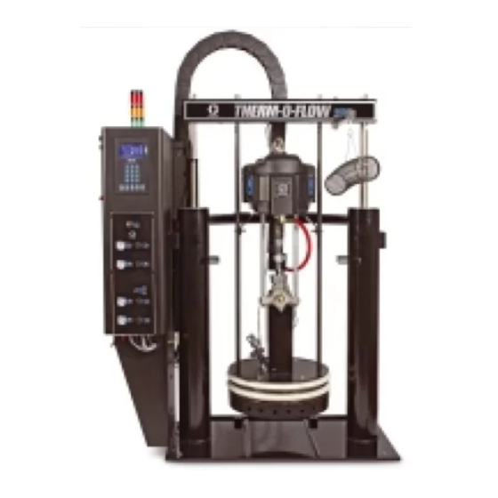
Page 8: Component Identification
Component Identification Component Identification Identification Component Component Identification Figure 1 TOF 200 Pneumatic Key: Key: Key: Key: Key: Key: Lift Strap Positions Main Power Switch Multi-Zone Low Power Temperature Control Module (MZLP) Air Motor Solenoid Light Tower Electrical Power Input Cable Track Air Motor Ram Plate Bleed Stick... - Page 9 Component Identification Integrated Air Air Controls Controls Integrated Integrated Controls Figure 2 Integrated Air Controls Key: Key: Key: Key: Key: Key: Blowoff Blowoff Blowoff Pressure Pressure Pressure Gauge Gauge Gauge Main Main Air Main Air Slider Slider Slider Valve Valve Valve Displays the blowoff pressure.
- Page 10 Component Identification Electrical Control Control Enclosure Enclosure Electrical Electrical Control Enclosure Figure 3 Electrical Enclosure Key: Key: Key: Key: Key: Key: Multi-Zone Low Power Temperature Platen SSR (65A) Control Module (MZLP) Platen Contactor Ventilation Grill Platen Fuse Electrical Control Panel Transformer Circuit Breaker Automatic Wiring Board (AWB) Transformer Fuse...
-
Page 11: Advanced Display Module (Adm)
Component Identification Advanced Display Display Module Module (ADM) (ADM) Advanced Advanced Display Module (ADM) NOTICE NOTICE NOTICE To prevent damage to the softkey buttons, do not The ADM display shows graphical and text press buttons with sharp objects such as pens, information related to setup and spray operations. - Page 12 Component Identification Figure 5 Back View Part Number and Identification Label Module Status LEDs USB Interface Light Tower (Optional) CAN Cable Connection (Power Supply and Communication) Software Token Access Panel Table 1 1 1 ADM ADM LED LED Status Status Descriptions Descriptions Table Table...
- Page 13 Component Identification Screen Components Components Screen Screen Components 1. Screen Order 2. Current date and time 3. Operating Mode 4. Faults, Status 5. MZLP Plug Identifier 6. Zone Setpoint Temperature 7. Zone Actual Temperature Description Operating Operating Operating Mode Mode Mode Description Description...
-
Page 14: Overview
Air and and Fluid Fluid Hoses Fluid Hoses Hoses The Therm-O-Flow requires Graco single-circuit material hoses rated at a maximum of 1250 watts. Make sure all air and fluid hoses are properly sized for the system. Heat Heat Heat Control... -
Page 15: Setup
Setup Setup Setup Setup 5. Make sure there is easy access to an appropriate electrical power source. The National Electrical Code requires 3 ft (0.9 m) of open space in front of the electrical panel. Comply with all local 1. Unpack the ram codes and regulations. -
Page 16: Mechanical Setup
4. Ensure drum low and empty sensors (C) are mounted as shown. 1. Fill displacement pump wet cup 2/3 full with Note Graco Throat Seal Liquid (TSL™) for Butyl and PSA materials. The Drum Low and Empty Sensors are used to indicate that a drum is empty. -
Page 17: Install Heated Hose
Setup Install Heated Heated Hose Hose Install Install Heated Hose 5. For proper operation, cables must be plugged into zones 1–2 and 3–4 at all times. To connect a hose to a fluid control device or heated 6. Install cap on any unused MZLP electrical manifold. -
Page 18: Connect Multiple Devices
Setup Connect Multiple Multiple Devices Devices Connect Connect Multiple Devices • Connect fluid control devices to a heated hose or the electrical enclosure. Use accessories if necessary. If your application requires multiple fluid control devices: • Setup all heat zones on Heat-A and Heat-B screens. -
Page 19: Connect Power
Setup Connect Power Power Connect Connect Power 2. Thread the wire from the power source into the control panel housing, and then connect the The electrical control panel comes already attached power source wires to the appropriate terminals and wired to the ram, however before the supply unit on the DISCONNECT switch. -
Page 20: Grounding
Setup Grounding Grounding Grounding Material drums: drums: follow local code. Use only metal Material Material drums: drums placed on a grounded surface. Do not place Ground the unit as instructed here and in the the drum on a nonconductive surface, such as component manuals. -
Page 21: Check Sensor Resistance
Setup Check Sensor Sensor Resistance Resistance Check Check Sensor Resistance Table 3 3 3 RTD RTD Sensors Sensors Table Table Sensors MZLP MZLP Plug Plug Component Component RTD RTD Range Range MZLP MZLP MZLP MZLP Plug Component Range (Ohms) (Ohms) (Ohms) Ram Plate 100 +/- 2... -
Page 22: Check Heater Resistance
Setup Check Heater Heater Resistance Resistance Check Check Heater Resistance 2. Make electrical resistance checks for the components. 3. Replace any parts whose resistance readings do not comply with the ranges listed in tables. Note To reduce risk of injury or damage to equipment, Check resistance at ambient room conduct these electrical checks with the main temperature 63°–... -
Page 23: Select Adm Settings
Setup Select ADM ADM Settings Settings Select Select Settings 5. Set primary system setpoint and setback temperatures for the pump, platen, and heat zones on the Heat-A screens. Note Appendix A— ADM, page 96 detailed ADM information, including general operation. 1. - Page 24 Setup 8. Set the temperature and mass units on the 9. To setup the optional Schedule function, see Advanced 2 screen. Set the specific gravity of Schedule, page the material for Material Tracking functionality. The schedule function allows the system to automatically enable and disable heating and setback at specified times.
-
Page 25: Connect Plc
Setup Connect PLC Connect Connect Table 7 7 7 Output Output Error Error States States Table Table Output Error States Error Error State Error State State Bit Error Error State Error State State Bit High High High Machine is good, no errors are present A PLC can control and monitor all items Active Unit... - Page 26 Setup 5. Connect the PLC to connectors H1 and H2. Note Each connector has four signals. The MZLP board specifies the input range for each signal. See the following table for pin assignments. Figure 14 H1 Customer Customer Input Input Customer Input Signal...
- Page 27 Setup PLC Connections Connections Connections Block Block Diagrams Block Diagrams Diagrams The following block diagrams show how to connect customer inputs and outputs to the MZLP. For convenience, each system ships with connector kit 24P176. If a connector is lost or damaged, order kit 24P176 for replacements.
-
Page 28: Operation
Operation Operation Operation Operation NOTICE 1. Turn the main power switch ON. The Graco logo NOTICE NOTICE will display until communication and initialization Use fluids that are chemically compatible with is complete. the equipment wetted parts. See Technical Specifications in all of the equipment manuals. -
Page 29: Load Material
Operation Load Material Material Load Load Material 4. Fill displacement pump wet cup 2/3 full with Graco Throat Seal Liquid (TSL™) for Butyl and PSA materials. NOTICE NOTICE NOTICE Note To prevent damage to platen wipers, do not use a drum of material that has been dented or damaged. -
Page 30: Heat Up System
Operation Heat Up Up System System Heat Heat System 7. Remove the platen bleed stick (R). To reduce the risk of bursting a hose, never pressurize a hot melt system before turning on the heat. The air will be locked from the air motor until all temperature zones are within a preset window of the temperature setpoints. -
Page 31: Prime Pump
Operation Prime Pump Pump Prime Prime Pump 4. Adjust the air motor slider valve (CM) to the open position. 1. Ensure that the system has completed the heat soak cycle. The display status bar should read Active. Active Active 2. Adjust the air motor air regulator (CK) to 0 psi. 5. - Page 32 Operation 7. If a new drum was installed and the unit is 9. Prime the pump until it moves smoothly in equipped with proximity sensors, press the Pump both directions with no air popping or erratic movement and close the main air slider valve (CA).
-
Page 33: Prime System
Operation Prime System System Prime Prime System 7. Close the main air slider valve (CA) and release trigger lock. 8. Engage trigger lock. 1. Close the main air slider valve (CA). Figure 22 Trigger Lock Engaged 9. Press to engage material tracking. 2. -
Page 34: Pressure Relief Procedure
Operation Pressure Relief Relief Procedure Procedure Pressure Pressure Relief Procedure 3. Set the ram director valve (CC) to the neutral position. Follow the Pressure Relief Procedure whenever you see this symbol. This equipment stays pressurized until pressure is manually relieved. To help prevent serious injury from pressurized fluid, such as skin injection, splashing fluid and moving parts, follow the Pressure Relief Procedure when you stop spraying... -
Page 35: Shutdown
Operation Shutdown Shutdown Shutdown Table 9 9 9 Schedule Schedule Screen Screen Color Color Identification Identification Table Table Schedule Screen Color Identification Description Color Color Color Description Description Green System on 1. Press to disable the heaters and pump. The screen will say “Inactive”. If using the Yellow Setback Schedule function, the heaters and pump will be... -
Page 36: Change Drums
Operation Change Drums Drums Change Change Drums 2. Push in the air motor slider valve (CM) to stop the pump. To prevent serious burns from dripping material, never reach under the heated platen after the platen is out of the drum. Follow the procedure to change the drum on a fully heated system. -
Page 37: Troubleshooting
Troubleshooting Troubleshooting Troubleshooting Troubleshooting Light Light Light Tower Tower (Optional) Tower (Optional) (Optional) Description Signal Signal Signal Description Description Red Light Off If green light is also off, system power may be off or system operating mode is Inactive. If green is on or flashing, there are no active errors. - Page 38 Troubleshooting Error Codes Codes Error Error Codes There are three types of errors that can occur. Errors The last digit of the error code indicates which are indicated on the display as well as by the optional system component the error applies. The “#” (pound) light tower.
- Page 39 Troubleshooting Code Code Code Description Description Description Type Type Type Cause Cause Cause Solution Solution Solution A3MF Alarm AWB Clean Fan Cooling inlet Clean inlet screen. Filter screen is dirty A4 _ High Current Alarm Defective or Verify accessory is rated for 240 VAC. Unit _ Zone _ shorted to Verify heater resistance and check for shorts to...
- Page 40 Troubleshooting Code Code Code Description Description Description Type Type Type Cause Cause Cause Solution Solution Solution AWB not Alarm AWB not Ensure connections between the ADM and hardware CACV present Unit responding are secure. If a tandem system, ensure AWB 2 jumper is installed at startup.
- Page 41 Troubleshooting Code Code Code Description Description Description Type Type Type Cause Cause Cause Solution Solution Solution Low Temp. Unit Alarm Zone Reduce flow rate. _ Zone _ temperature Increase temperature of accessory upstream. too low Faulty accessory heater measure resistance between heater leads.
- Page 42 Troubleshooting Code Code Code Description Description Description Type Type Type Cause Cause Cause Solution Solution Solution Wiring Error Alarm Incoming V6M# Correct the Wiring. Line MZLP _ power is wired incorrectly V8M# No Line Voltage Alarm Incoming line Verify transformer has the correct tap selected. MZLP _ voltage is less Verify CB-1 or FU-4, FU-5, and FU-6 are not...
- Page 43 Troubleshooting Ram Troubleshooting Troubleshooting Troubleshooting Problem Cause Solution Problem Problem Cause Cause Solution Solution Ram will not raise or lower. Closed main air valve or clogged air Open air valve; clear air line. line, Not enough ram air pressure. Increase ram air pressure. Worn or damaged ram piston.
- Page 44 Troubleshooting Heated Pump Pump Troubleshooting Troubleshooting Heated Heated Pump Troubleshooting See pump manual for additional pump troubleshooting information. Problem Cause Solution Problem Problem Cause Cause Solution Solution Rapid downstroke or upstroke (pump Material not heated to proper Check and adjust temperature to cavitation).
-
Page 45: Repair
Repair Repair Repair Repair Replace Wipers Wipers Replace Replace Wipers 2. Make sure the ram plate is down and the ram hand valve is in the OFF position. 1. To replace a worn or damaged wiper (V) raise the ram plate up out of the drum. Perform steps 1 through 7 of Change Drums, page 36 . -
Page 46: Separate The Air Motor And Pump
Repair 6. Disconnect the platen RTD wires from pin 3 and 2. Make sure the ram plate is down and the ram pin 6 from the J5 connector on the AWB. director valve (CC) is in the neutral position. Figure 27 RTD Wire Connections 2760 2770 White... - Page 47 Repair 10. Remove the air motor top cover. 17. Slide end of cable track outboard of the mounting plate. 11. Disconnect electrical cable from air motor. 18. Remove nuts (N) from follower lift rods. 12. Remove air line from air motor and air lines to the follower blow-off valve.
- Page 48 Repair Figure 28 334130D...
-
Page 49: Remove Platen
Repair Remove Platen Platen Remove Remove Platen 7. Remove the screws and covers. 1. Turn the main power switch off. 2. Disconnect the platen power wires and the ground wire from within the main control panel and pull out of conduit. 3. -
Page 50: Replace Mzlp Fuse
Repair Replace Replace Replace Pump Pump Pump RTD Fuse Fuse Kit Fuse Kit Fuse Fuse Fuse Part Part Part 24V289 F1, F2 250VAC, 25A, long, white 1. Turn the main power switch off. ceramic F3-F10 250VAC, 8A, fast acting, clear glass Spare fuse kit included with system. -
Page 51: Replace Mzlp
Repair Replace MZLP MZLP Replace Replace MZLP 6. To reassemble MZLP, Set MZLP rotary switch MZLP Rotary Rotary Switch Switch based on location. See MZLP MZLP Rotary Switch Table. Table Table 7. Use four screws (115) to install MZLP (111 or 112) to electrical enclosure. -
Page 52: Replace Mzlp Daughter Card
Repair Replace MZLP MZLP Daughter Daughter Card Card Replace Replace MZLP Daughter Card 5. Plug new daughter card (112a) into the MZLP (112). 6. Use screws (112b) to secure daughter card to MZLP (112). 7. Connect cables to new daughter card (112a). Note 1. -
Page 53: Replace Awb
Repair Replace AWB Replace Power Power Supply Supply Replace Replace Replace Replace Power Supply 1. Turn the main power switch off. 2. Note location of each cable, then unplug all cables from the AWB (205). Note For an AWB on a secondary system, remove connector (182) and connect to new AWB. -
Page 54: Replace Fan
Repair Replace Fan Replace Replace 6. Remove screws (141), grill (137), four nuts (139), rear fan grill (138), and fan (136). 1. Turn the main power switch off. 2. Disconnect plug from power outlet or turn off circuit breaker for incoming power. 3. -
Page 55: Replace Transformer
Repair Replace Transformer Transformer Replace Replace Transformer 13. Connect transformer output power harness (234) to power terminal connections. Torque to 25–27 in-lbs (2.8–3.1 N•m). Table Table Table 11 11 Transformer Transformer Output Transformer Output Output Power Power Power Harness Harness Harness Connections Connections... - Page 56 Repair Figure 34 Inside of Electrical Control Enclosure 334130D...
-
Page 57: Update Software
Repair Update Software Software Update Update Software 6. Turn system main power switch ON. NOTICE NOTICE NOTICE When software is updated on the ADM the software A status is shown while software is updating to is then automatically updated on all connected indicate progress. -
Page 58: Electrical Schematics
Electrical Schematics Electrical Electrical Schematics Electrical Schematics Schematics 7. Remove token (T). 8. Replace token access panel. 230V, 230V, 3 3 3 Phase/60 230V, Phase/60 Phase/60 Hz 9. Press to continue to the operation screens. 334130D... - Page 59 Electrical Schematics 400V, 3 3 3 Phase/50 Phase/50 Hz 400V, 400V, Phase/50 334130D...
- Page 60 Electrical Schematics 400–600VV, 3 3 3 Phase/60 Phase/60 Hz 400–600VV, 400–600VV, Phase/60 334130D...
- Page 61 Electrical Schematics AWB and and MZLP#1 MZLP#1 MZLP#1 334130D...
- Page 62 Electrical Schematics MZLP #2, #2, MZLP#3, MZLP#3, Overtemp, Overtemp, and MZLP MZLP MZLP#3, Overtemp, Pump Heaters Heaters Pump Pump Heaters 334130D...
- Page 63 Electrical Schematics MZLP Zones Zones MZLP MZLP Zones 334130D...
-
Page 64: Parts
Parts Parts Parts Parts Therm - - - O O O - - - Flow Flow 200 200 Supply Supply Unit Unit Therm Therm Flow Supply Unit 334130D... - Page 65 Parts Therm - - - O O O - - - Flow Flow 200 200 Supply Supply Unit Unit Therm Therm Flow Supply Unit Part Description Part Description Part Part Description Description Part Part Description Description - - - Frame 120186 BOLT, mounting, u-bolt 24W870 KIT, air controls;...
- Page 66 Parts Air Control Control Assembly Assembly Control Assembly Integrated Integrated Integrated Control Control Control For 24X026, 24X026, 24X026, Integrated Integrated Integrated Control Control For Control Integrated Integrated Control Integrated Control For Control TOF With With With Electrical Electrical Electrical Enclosure Enclosure Enclosure Hydraulic...
- Page 67 Parts Electrical Module Module Electrical Electrical Module 334130D...
- Page 68 Parts 334130D...
- Page 69 Parts Electrical Control Control Module Module Parts Parts Electrical Electrical Control Module Parts Part Description Part Description Ref. Ref. Part Ref. Part Description Description Ref. Ref. Ref. Part Part Description Description - - - ENCLOSURE, electrical - - - HARNESS, pump, mzlp1, tb, tof - - - BUSHING, strain relief, m40...
- Page 70 Parts Part Description Part Description Ref. Ref. Ref. Part Part Description Description Ref. Ref. Part Ref. Part Description Description - - - 102040 NUT, lock, hex HARNESS, input, mzlp1, (Primary assemblies only) 110755 WASHER, plain 127771 BRIDGE, plug-in, 2pos, (Primary assemblies only) ut16 121253 KNOB, display adj., ram...
- Page 71 Parts Electrical Panel Panel Electrical Electrical Panel 230V 230V 230V 400V/N 400V/N 400V/N Transformer Transformer Transformer Transformer Transformer Panel Transformer Panel Panel Shown Shown Shown Torque terminals to 25–27 in-lbs (2.8–3.1 N•m). Torque terminals to 13.3–16 in-lbs (1.5–1.8 N•m). Torque terminals to 4.53–6.2 in-lbs (0.5–0.7 N•m).
- Page 72 Parts 230V 230V 230V Panel Panel Panel 400V/N 400V/N 400V/N Panel Panel Panel Torque terminals to 25–27 in-lbs (2.8–3.1 N•m). Torque terminals to 13.3–16 in-lbs (1.5–1.8 N•m). Torque terminals to 4.53–6.2 in-lbs (0.5–0.7 N•m). 334130D...
- Page 73 Parts Electrical Panel Panel Parts Parts Electrical Electrical Panel Parts Ref. Part Part Part Description Description Description Qty. Ref. Part Part Part Description Description Description Qty. Ref. Ref. Qty. Qty. Ref. Ref. Qty. Qty. - - - - - - PANEL, elec, tof, 11ga, HARNESS, wire, ground, zinc...
- Page 74 Parts Merkur 2200, 2200, 23:1 23:1 Pump Pump Modules Modules Merkur Merkur 2200, 23:1 Pump Modules Coat inside of heater (309a, 309b) only to within Torque to 50–60 ft-lb (68–81 N•m). 0.75 in. (19 mm) of vertical ends with non-silicone Torque to 145–155 ft-lb (196–210 N•m).
- Page 75 Parts Merkur 2200, 2200, 23:1 23:1 Pump Pump Modules Modules Merkur Merkur 2200, 23:1 Pump Modules Description Description Ref. Part Description Description Ref. Part Description Description Ref. Ref. Part Part Ref. Ref. Part Part 24W754 MOTOR, air, 6 in, 4.75 24Z093 SENSOR, RTD stroke, blue...
- Page 76 Parts Merkur 3400, 3400, 36:1 36:1 Pump Pump Modules Modules Merkur Merkur 3400, 36:1 Pump Modules Coat inside of heater (309) only to within 0.75 in. Torque to 50–60 ft-lb (68–81 N•m). (19 mm) of vertical ends) with non-silicone heat Torque to 145–155 ft-lb (196–210 N•m).
- Page 77 Parts Merkur 3400, 3400, 36:1 36:1 Pump Pump Modules Modules Merkur Merkur 3400, 36:1 Pump Modules Description Description Ref. Part Description Description Ref. Part Description Description Ref. Ref. Part Part Ref. Ref. Part Part 24R015 MOTOR, assy, air, 7.5 in 120186 BOLT, mounting, u-bolt ,blue...
- Page 78 Parts NXT 6500, 6500, 70:1 70:1 Pump Pump Modules Modules 6500, 70:1 Pump Modules Torque to 50–60 ft-lb (68–81 N•m). After fastening band clamp (412), secure excess with fiberglass tape. Torque to 145–155 ft-lb (196–210 N•m). Coat inside of heater (407) only to within 0.75 in. Coat mounting surface of sensor mounting block (19 mm) of vertical ends) with non-silicone heat (411) with non-silicone heat sink compound.
- Page 79 Parts NXT 6500, 6500, 70:1 70:1 Pump Pump Modules Modules 6500, 70:1 Pump Modules Description Description Ref. Part Description Description Ref. Part Description Description Ref. Ref. Part Part Ref. Ref. Part Part - - - N65LR0 MOTOR, 6500, low-noise, CONDUCTOR, ground remote C38162 SCREW, machine...
- Page 80 Parts Pump Shield Shield Pump Pump Shield Description Description Ref. Ref. Ref. Part Part Part Description Description Ref. Ref. Ref. Part Part Part Description Description 24W974 COVER, pump, bottom 184090 LABEL, warning 24W975 COVER, pump, right 104088 RIVET, blind 24W976 COVER, pump, left 15J075 LABEL, safety, hot surface and shock...
- Page 81 Parts Heated Platens Platens Heated Heated Platens 24V633, 24V633, 24V633, Heated Heated Drum Heated Drum Platen, Drum Platen, Platen, Mega Mega - - - Flo Mega Flo (Code (Code E E E - - - option (Code option M) option 24V634, 24V634, 24V634, Heated...
- Page 82 Parts 24V633, Heated Heated Drum Drum Platen, Platen, Mega Mega - - - Flo Flo (Code (Code E E E - - - option option M) 24V633, 24V633, Heated Drum Platen, Mega (Code option 24V634, Heated Heated Drum Drum Platen, Platen, Standard Standard Grid(Code Grid(Code E E E - - - option...
- Page 83 Parts Heater Terminal Terminal Patterns Patterns Heater Heater Terminal Patterns 24V633 24V633 24V633 24V634, 24V634, 24V634, 24V635 24V635 24V635 16.5 Ohms across pairs 19.25 Ohms across pairs Platen Coil Coil Wiring Wiring Platen Platen Coil Wiring 24V633 24V634, 24V635 24V635 24V633 24V633 24V634,...
- Page 84 Parts Drum Ram Ram Post Post Saddle Saddle Clamp Clamp Drum Drum Post Saddle Clamp C32463 C32463 C32463 Option Option Option H H H - - - 1 1 1 Part Part Part Description Description Description Part Part Part Description Description Description BOLT, U, 7 in.
- Page 85 Parts Heavy Duty Duty Drum Drum Band Band Clamp Clamp Heavy Heavy Duty Drum Band Clamp 918395 918395 918395 Option Option Option H H H - - - 3 3 3 Part Part Part Description Description Description Part Part Part Description Description Description...
- Page 86 Parts Fiber Drum Drum Reinforcement Reinforcement Clam Clam Shell Shell Clamp Clamp Fiber Fiber Drum Reinforcement Clam Shell Clamp 918397 918397 918397 OPTION OPTION OPTION H H H - - - 2 2 2 Part Part Part Description Description Description Part Part Part...
- Page 87 Parts Vent Hood Hood Kit, Kit, 233559 233559 Vent Vent Hood Kit, 233559 Part Part Part Description Description Description Part Part Part Description Description Description - - - VENT hood 100016 WASHER, lock 112166 SCREW, cap, sch C14038 LABEL, warning Replacement Warning labels, signs, tags, and cards are available at no cost.
-
Page 88: Accessories And Kits
Accessories and Kits Accessories and and Kits Kits Flow Control Control and and Manifolds Manifolds Accessories Accessories Kits Flow Flow Control Manifolds Part No. Description Part Part Description Description Wiper Kits Kits Wiper Wiper Kits 243700 Heated Air Operated Mastic Pressure Regulator, 240V 243656 23:1 Heated Pressure Compensator... - Page 89 Accessories and Kits Heated Hoses Hoses and and Fittings Fittings Heated Heated Hoses Fittings Hose Hose Hose Diameter Diameter Diameter - - - 6 6 6 - - - 8 8 8 - - - 10 - - - 12 - - - 16 - - - 20 (9/16...
- Page 90 Accessories and Kits Hose Hose Hose Diameter Diameter Diameter - - - 6 6 6 - - - 8 8 8 - - - 10 - - - 12 - - - 16 - - - 20 (9/16 (9/16 in in in - - - 18 (9/16 (3/4 (3/4 in in in - - - 16...
- Page 91 Accessories and Kits 8 8 8 Channel Channel Upgrade Upgrade Kit, Kit, 24V755 24V755 Channel Upgrade Kit, 24V755 Use this kit to upgrade a 4 Channel system to a 8 channel system. Part Part Part Description Description Description Part Part Part Description Description...
-
Page 92: Zone Upgrade Kit Installation
Accessories and Kits 8 8 8 Zone Zone Upgrade Upgrade Kit Kit Installation Installation Zone Upgrade Installation 5. Open the electrical enclosure door. Note Do not force the electrical connection. Minimal force is required to seat the connector. If resistance is felt, stop, and verify the connector orientation. - Page 93 Accessories and Kits 12 Channel Channel Upgrade Upgrade Kit, Kit, 24V756 24V756 Channel Upgrade Kit, 24V756 Use this kit to upgrade a 8 channel system to a 12 channel system. Part Description Part Description Part Part Description Description Part Part Description Description MODULE, GCA, MZLP...
- Page 94 Accessories and Kits 334130D...
-
Page 95: Zone Upgrade Kit Installation
Accessories and Kits 12 Zone Zone Upgrade Upgrade Kit Kit Installation Installation Zone Upgrade Installation 5. Open the electrical enclosure door. Note Do not force the electrical connection. Minimal force is required to seat the connector. If resistance is felt, stop, and verify the connector orientation. -
Page 96: Appendix A- Adm
Appendix A— ADM Appendix A— A— ADM Appendix Appendix A— General Operation Operation Enable, Disable Disable Heating Heating System System General General Operation Enable, Enable, Disable Heating System ADM Power Power Power To enable or disable the entire heating system, press . - Page 97 Appendix A— ADM Icons Icons Icons Screen Screen Icons Screen Icons Icons Softkey Softkey Softkey Icons Icons Icons These are frequently used icons on the screens. The following icons appear in the ADM, directly to The following descriptions explain what each icon the left or right of the soft key which activates that represents.
-
Page 98: Operation Screens
Appendix A— ADM Operation Screens Screens Operation Operation Screens Color A A A and and B B B Zone Zone Status Status Color Color Zone Status Yellow Outside of advisory Home Home Home range Green/Yellow Flashing Warmup This screen shows the temperature state of the system and material usage. -
Page 99: Setup Screens
Appendix A— ADM Errors Errors Errors CAN: 24 VDC power supply voltage reading (18–28 CAN: CAN: VDC) DI: System Digital Inputs 0: Drum Empty 1: Drum Low 2: Pump Cycle Switch Up 3: Pump Cycle Switch Down DO: System Digital Outputs 0: Pump Solenoid 1: Not Used 2: Not Used... - Page 100 Appendix A— ADM Password Password Password Pump Inactive Inactive Timeout: Timeout: If no pump movement is Pump Pump Inactive Timeout: detected or either pump for (x) amount of time, all heated zones enter setback mode. After an additional If the password is not “0000”, the password must be amount of time (x), the heat will turn off.
- Page 101 Appendix A— ADM Advanced 2 2 2 Advanced Advanced Disable USB USB Downloads/Uploads: Downloads/Uploads: Disables use of Disable Disable Downloads/Uploads: the USB for downloading and uploading. Disable Disable Disable USB USB Log Log Errors: Errors: Errors: When disabled, the system will not warn the user when logs are full.
- Page 102 Appendix A— ADM Heat - - - A A A Heat Heat Use these screens to set target and setback temperatures for the pump, platen, and zones. Select which system needs to use the heated accessory. Zone Zone Types: Zone Types: Types: •...
- Page 103 Appendix A— ADM Maintenance - - - A A A Schedule Maintenance Maintenance Schedule Schedule The system will notify the user at the set interval that Use this screen to set times that the system maintenance is required. The fields in boxes can will automatically enable and disable heating.
-
Page 104: Appendix B - Usb Data
ADM. around-the-clock operation. Once full, the system will When downloading from multiple ADMs, there will be overwrite the oldest data. one sub-folder in the GRACO folder for each ADM. Note The log files should be opened in a spreadsheet program. -
Page 105: Usb Logs
If the SETTINGS.TXT or DISPTEXT.TXT These logs (5-BLACKB.CSV, 6-DIAGN.CSV) are files remain in the UPLOAD folder, they will designed to provide useful information to Graco when be uploaded every time the USB drive is calling for technical assistance. inserted into the corresponding ADM. To... -
Page 106: System Language File
Appendix B — USB Data System Language Language File File System System Language File Modify the second column of the custom language file as needed and then follow the Upload Instructions, page 104, to install the file. The system language file name is DISPTEXT.TXT and is stored in the DOWNLOAD folder. -
Page 107: Dimensions
Dimensions Dimensions Dimensions Dimensions Ram Mounting Mounting and Mounting and Clearance Clearance Clearance A A A B B B C C C D D D E E E F F F G G G J J J in. (mm) (mm) in. -
Page 108: Technical Specifications
Technical Specifications Technical Specifications Specifications Technical Technical Specifications Therm Therm- - - O O O - - - Flow Therm Flow Flow 200 200 Hot Hot Melt Melt System Melt System System U.S. U.S. U.S. Metric Metric Metric Displacement pump effective area 1.24 in. -
Page 109: Graco Standard Warranty
With the exception of any special, extended, or limited warranty published by Graco, Graco will, for a period of twelve months from the date of sale, repair or replace any part of the equipment determined by Graco to be defective. This warranty applies only when the equipment is installed, operated and maintained in accordance with Graco’s written recommendations.
Need help?
Do you have a question about the Therm-O-Flow 200 and is the answer not in the manual?
Questions and answers