Graco Therm-O-Flow 20 Instructions - Parts Manual
Air-powered ram heated pail unloaders
Hide thumbs
Also See for Therm-O-Flow 20:
- Instructions - parts manual (112 pages) ,
- Instructions-parts list manual (108 pages) ,
- Instructions - parts manual (78 pages)
Table of Contents
Advertisement
Quick Links
Instructions - Parts
Therm-O-Flow
Air-powered Ram Heated Pail Unloaders
5 gallon (20 liter) pail size, 3" (76 mm) dual post Ram
Read warnings and instructions.
See page 3 for maximum working pressure and
other model information.
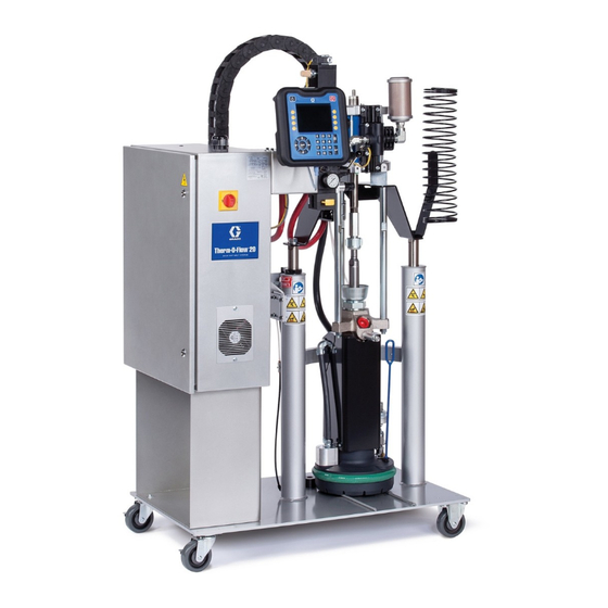
Therm-O-Flow 20 with Bulldog
Graco Inc. P.O. Box 1441 Minneapolis, MN 55440-1441
Copyright 2003, Graco Inc. is registered to I.S. EN ISO 9001
®
®
™
/King
pump
20
Therm-O-Flow 20 with President
309858D
™
pump
Advertisement
Table of Contents

Related Manuals for Graco Therm-O-Flow 20


Summary of Contents for Graco Therm-O-Flow 20
- Page 1 See page 3 for maximum working pressure and other model information. ® ™ ™ Therm-O-Flow 20 with Bulldog /King pump Therm-O-Flow 20 with President pump Graco Inc. P.O. Box 1441 Minneapolis, MN 55440-1441 Copyright 2003, Graco Inc. is registered to I.S. EN ISO 9001...
-
Page 2: Table Of Contents
Before Servicing ......21 Graco Information ......66 Ram Service . -
Page 3: Models
Models Models Max. Fluid Working Part Number Motor/Pump Ratio Pressure Voltage Page 918522 President 15:1 1800 psi (12 MPa, 124 bar) 480 VAC page 30 918532 President 15:1 1800 psi (12 MPa, 124 bar) 240 VAC page 30 246653 President (no control) 15:1 1800 psi (12 MPa, 124 bar) 240 VAC... - Page 4 Manual Conventions WARNING INJECTION HAZARD High-pressure fluid from gun, hose leaks, or ruptured components will pierce skin. This may look like just a cut, but it is a serious injury that can result in amputation. Get immediate medical attention. • Do not point the gun at anyone or at any part of the body.
- Page 5 Misuse can cause serious injury or death. • For professional use only. • Use equipment only for its intended purpose. Call your Graco distributor for information. • Read manuals, warnings, tags, and labels before operating equipment. Follow instructions. • Check equipment daily. Repair or replace worn or damaged parts immediately.
-
Page 6: Installation
Installation Installation Key: Air Line Filter Ram Air Regulators Bleed-type Master Air Valve - required Air Line Lubricator Pump Bleed-type Master Air Valve - required Depressurization Valve Pump Air Regulator Air Motor Pressurization Kit (King/Bulldog units only) Main Air LIne Supply Pump Electrical Control Panel Ram Control Lever... -
Page 7: Unpacking
Installation Unpacking Air Line Modules Unpack the Therm-O-Flow 20 as follows: 4-Regulator Air Control Module (246587) 1. Inspect the shipping box for damage; immediately Refer to page 36-38. contact the carrier if damaged. This module includes the following components: 2. Open the box and inspect the contents for loose or damaged parts. -
Page 8: Grounding
Installation Location 3-Regulator Air Control Modules (234236, not shown) Refer to the dimensional drawings, page 60, for ram This module includes the following components: mounting and clearance dimensions. • Pump Bleed-type Master Air Valve (C): is installed Make sure: so the valve is easily accessible and located down- stream from the air regulator. -
Page 9: Electrical Control Panel
Installation Electrical Control Panel Have a trained electrician connect the electrical control panel to a grounded electrical source that has the required service ratings: Electrically Connect Hoses Assemble hose and gun components. Follow the gun Control Full instructions. Panel Load Model: Zones: VAC: Hz: Phase:... -
Page 10: Check Resistance
Installation Check Resistance 3-Zone RTD Sensors Zone Component Terminals Value Range Follower 1311, 1321 108 ± 2% ohms WARNING Dispense Hose 1531, 1541 108 ± 2% ohms Dispense Gun 1601, 1611 108 ± 2% ohms The system must be properly grounded. See Ground- ing, page 8. -
Page 11: Temperature Controller Settings
Installation Heaters for 4-Zone Control Panels Graco Factory P, I, and d Settings The table lists the P (proportional), I (integral), and d Zone Component Terminals Value Range (derivative) settings for standard control panels. These Follower 3L1 & 3L3 98-127 ohms settings are preset at the factory. -
Page 12: Flushing
1. Select a solvent that is compatible with the equip- ment wetted parts and the material being flushed. 6. Open the dispense valve over a waste container Check with your Graco distributor or the material during system heatup to relieve pressure as mate- supplier for a recommended solvent. -
Page 13: Loading Material
Start Up Loading Material b. If necessary, stop lowering the follower plate to adjust the pail position to align with the follower plate. WARNING c. As the follower plate enters the pail, remove the bleed stick to allow trapped air between the fol- lower plate and the top of the material to Material and equipment are hot. -
Page 14: Operation
Operation Operation Pressure Relief Procedure 10. To relieve pressure in the ram, see the Ram Pres- sure Relief Procedure, page 21. WARNING Raising and Lowering Ram WARNING Read warnings, page 4, and follow the Pressure Relief Procedure whenever you: • are instructed to relieve pressure •... -
Page 15: Daily Start-Up Procedure
Operation Daily Start-up Procedure 7. Turn the pump air supply ON and set the regulator for normal operation. 8. Dispense material into a waste container. Adjust the WARNING flow rate as needed. Using Optional 7-Day Timer • Material and equipment are hot. Avoid contact. The 7-day timer can be set to automatically turn the heat Wear protective clothing. -
Page 16: Changing Empty Pails
Operation Changing Empty Pails 4. Being careful not to damage the follower wiper or touch hot material, scrape material from the follower plate and wiper. CAUTION 5. Follow Loading Material procedure, page 13-13, • To avoid damaging pumps, do not operate when steps 1-6, except step 3 (lubricate the wiper). -
Page 17: Reading Electrical Control Panel Indicators
Operation Reading Electrical Control Panel Indicators Use the table and F . 5 below to read electrical control panel indicators. For information on setting the temperature controllers, see Setting Temperature Controllers in Manual 309100. Indicator Light No. Indicator Light is Meaning Power On/Ground Power is on and ground is connected. - Page 18 Operation High Temperature Alarm Ground Fault Interrupt Should a component temperature go outside the preset The control panel includes a ground fault interrupt (GFI) range for any of the zones, power to heated components circuit breaker (F . 7). If the main electrical disconnect is interrupted, and the HIGH TEMPERATURE ALARM is ON, but all lights on the electrical control panel are off, light turns ON.
-
Page 19: Troubleshooting
Troubleshooting Troubleshooting Problem Cause Solution Ram does not raise or lower. Main air valve closed. Open air valve. Air line clogged. Clear air line. Ram air pressure too low. Increase ram pressure. Worn or damaged piston. Replace piston. See manual 310523. -
Page 20: Heated Pump
Troubleshooting Heated Pump See the pump manual for more information. Problem Cause Solution Rapid down or up stroke (pump Material not heated to proper tem- Check and adjust temperature set point. cavitation). perature. Air trapped in pump. Purge air from the pump - page 13, step Downstroke: Lower check in pump Repair pump. -
Page 21: Service
Service Service Before Servicing 1. Remove material pail. Follow Changing Empty Pails procedure, page 16, step 1-4. Follow the procedure’s warnings and cau- tions. WARNING Read warnings, page 4. 2. Follow the Pressure Relief Procedure, page 14. 3. Follow the Ram Pressure Relief Procedure, below. Ram Service For more information on servicing the ram, see manual 310525. -
Page 22: Follower Service
Replacing Heat Sensors For more information about the follower plate, refer To replace wires connecting the follower to the to pages 26-27. pump, see Manual 310530 or contact your Graco distributor. 1. Follow Before Servicing procedure, page 21. Replacing Wipers 2. -
Page 23: Check-Mate 800 Pump/Motor Service
Service Check-Mate 800 Pump/Motor or a razor, to carefully scrape the sealant off the shroud seams. Service 9. Pumps C03509 and C03512 only: disconnect the junction box from the pump. For specific information about servicing the a. Remove the junction box cover. Check-Mate 800 pump, see manual 308570 or 310530. - Page 24 • Apply RTV sealant to the pump shrouds before assembling them For more information, see manual 310530, or call your Graco distributor. Removing Follower Plate Refer to page 41. 1. Remove the pump by following steps 1-12 of the Removing the Pump Assembly procedure.
- Page 25 Service 240/480 Volt Ram Plate Assembly Wiring (3 Zone Control) 240V FOLLOWER HEATERS FHA1 FHB1 FHA2 FHB2 480V FOLLOWER HEATERS FHA1 FHB1 FHA2 FHB2 . 12 309858D...
- Page 26 Service 240 Volt Ram Plate Assembly Wiring (4 Zone Control) To Control Box FHA1 FHB1 PUMP SENSOR FHA2 FHB2 FOLLOWER SENSOR PHT1 PHB1 PROX SWITCH PHT2 PHB2 PUMP GROUNDING SCREW FOLLOWER GROUNDING SCREW PUMP HEATERS 600/860W 600/860W FOLLOWER HEATERS . 13 309858D...
- Page 27 Service 480/575 Volt Ram Plate Assembly Wiring (4 Zone Control) TO CONTROL BOX FHA1 FHB1 PUMP SENSOR FHA2 FHB2 FOLLOWER SENSOR PHT1 PHB1 PROX SWITCH PHT2 PHB2 PUMP GROUNDING SCREW FOLLOWER GROUNDING SCREW PUMP HEATERS 600/860W 600/860W FOLLOWER HEATERS . 14 309858D...
-
Page 28: President Pump/Motor Service
Service President Pump/Motor Service 4. Remove the air lines (116, 117) from the blow-off valve (103). 5. Remove the 6 screws (109) and washers (108). For more information on servicing the pump lower assembly, refer to manual 307431. 6. Slide off the follower plate (9). Removing Pump from Air Motor 1. -
Page 29: Inspection Frequency
Service Inspection Frequency Ground Fault Interrupt Periodically (once a month) test the ground fault inter- rupt switch by pushing the TEST button. See the litera- ture that came with the electrical control panel. Periodically (once a month), inspect the ram guide sleeves, rods and cylinders for wear or damage, replace Removing/Replacing CB100 all worn parts. -
Page 30: Parts
Parts Parts Therm-O-Flo 20 Models 918522, 918532, and 246653 3” (76 mm) Ram, 15:1 President, with silicone follower wiper, 918522 - 480 VAC, 918532 - 240 VAC 33,34 Torque to 20-30 ft-lbs (27-41 N•m) Torque to 30-40 ft-lbs (41-54 N•m) Fill packing nut 1/2 full of TSL (43) Tie-wrap armored portion of sensor onto conduit leading up to junction box;... - Page 31 Parts Model 918522 Model 918532 With Electrical Control, Includes 1-45 With Electrical Control, Includes 1-45 Model 246653 Part No. Description Qty. Without Electrical Control, Includes 1-12, 15, 22-45 918506 KIT, depressurizing (see page 37) 234236 CONTROL BOX C31197 KIT, hose support Part No.
-
Page 32: Therm-O-Flo 20 Models 918344 And 918437
Parts Therm-O-Flo 20 Models 918344 and 918437 3” (76 mm) Ram, 31:1 Bulldog, Therm-O-Flo 20 Heated Check-Mate 800, with silicone follower wiper, 918344 - 480 VAC, 918437 - 240 VAC REF 1 23, 24, 25 Model 918437 only. Remove excess armored portion of sensor supplied with heated follower (13) prior to installing into junction box. - Page 33 Parts Model 918344 Ref. Ref. Part No. Description Qty. Part No. Description Qty. C06299 MUFFLER; #10-32 unf 241201 PUMP, 31:1 Bulldog C19019 UNION, swivel C31197 KIT, hose support 244757 INDUCTOR, heated; see page 41 C19127 BOLT; 3/8-16 UNC x 1.5” 617349 ELECTRICAL CONTROL, 480 V, C19200 WASHER;...
- Page 34 Parts Therm-O-Flo 20 Model C59398 3” (76 mm) Ram, 65:1 King, Therm-O-Flo 20 Heated Check-Mate 800, with silicone follower wipers, 480 VAC REF 9 23, 24, 25 Remove excess armored portion of sensor supplied with heated follower (13) prior to installing into junction box. 309858D...
- Page 35 Parts Model C59398 Ref. Ref. Part No. Description Qty. Part No. Description Qty. C06299 MUFFLER; #10-32 unf 241200 PUMP, 65:1 King; see manual C19019 UNION, swivel; 1/2-14 310530 244757 INDUCTOR, heated; see page 41 C31197 KIT, hose support 617349 ELECTRICAL CONTROL, 480 V, C19127 BOLT;...
-
Page 36: Part No. 246587
Parts Part No. 246587 4-Regulator Ram Air Control Module Ref. Part No. Description Qty. 234236 CONTROL BOX 101682 SCREW; 1-1/4-20 x 5/8” C11034 LUBRICATOR, oil C11029 REGULATOR, air C36260 GAUGE, air pressure 113269 VALVE, ball, vented C19024 ELBOW, swivel; 1/2-14 npsm x 1/2-14 nptf C19197 WASHER;... -
Page 37: Part No. 918506
Parts Part No. 918506 Depressurizing Kit Ref. Ref. Part No. Description Qty. Part No. Description Qty. C19681 BUSHING; 3/4 x 1/4 npt C20572 GRIP; 90° cable 113269 VALVE, ball,vented, .500 C20874 O-RING, conduit sealing 155470 UNION, swivel, 90° C20715 LOCKNUT, conduit; 1/2” 110332 ADAPTER C20865 BUSHING;... - Page 38 Parts Part No. 246587 (UP) (DOWN) (BLOW-OFF) Air Motor 1/2 npt air inlet 309858D...
-
Page 39: Part No. C03510
Parts Part No. C03510 Pump Air Motor Mounting Kit Ref. Part No. Description Qty. 106166 NUT, M16 x 2 190000 ROD, tie 184129 COLLAR, coupling 186925 NUT, coupling; 1-1/4-12 UNF 309858D... -
Page 40: Part No. 918433
Parts Part No. 918433 Proximity Switch Kit (pump activity) for use with President pumps 3, 4 6, 7 Ref. Ref. Part No. Description Qty. Part No. Description Qty. C20715 LOCKNUT, conduit; 1/2” C50174 CABLE, proximity C20865 BUSHING; conduit; 1/2 npt 517469 SWITCH, proximity 617417 BRACKET, switch mounting C19209 WASHER, lock;... -
Page 41: Part No. 244757
Parts Part No. 244757 Heated Follower Plate Kit with smooth bottom for use with Heated Check-Mate 800 pump modules 123, 124 Ref. Ref. Part No. Description Qty. Part No. Description Qty. 100176 BUSHING; 3/8-18 x 1/4-18 npt 244710 PLATE, heated; smooth bottom 115948 ELBOW, 90°;... -
Page 42: Part No. 244754
Parts Part No. 244754 Heated Follower Plate Kit with finned bottom for use with President pump assemblies 109 108 105 106 113, 123, 124 Ref. Ref. Part No. Description Qty. Part No. Description Qty. 100176 BUSHING; 3/8-18 x 1/4-18 npt 244707 PLATE, heated;... - Page 43 Parts 309858D...
-
Page 44: Part No 617300 And 617484
FU100/101, 600 V (for Part No. 617300) 15C347 1792 FU100/101, 600 V (for Part No. 617485) 15C348 (2) SPARE FU103/104, 250 V (for Part No. 617485) 15C496 To order other parts, contact your Graco distributor. TOTAL (31), TYPE CA1 309858D... - Page 45 Parts Part No 617300 and 617484 Standard, 3-zone Electrical Control Panel (exterior) 617300 - 480 VAC (shown), 617484 - 240 VAC TC129 TC151 TC158 DH/DG HOSE FOLLOWER LINE VOLTAGE: PHASE: FREQ: 60HZ FULL LOAD AMPS: ELECTRICAL PANEL PART No.: 617300 OUT1 OUT2 ALM1...
-
Page 46: Part No 617349 And 617485
1662 FU179, 125 V 15C343 FU100/101/102, 600 V (for Part No. 617349) 15C346 1711 1752 FU100/101/102, 250 V (for Part No. 617484) 15C349 1772 To order other parts, contact your Graco distributor. 1792 (1) SPARE TOTAL (34), TYPE CA1 309858D... - Page 47 ALM1 ALM2 CB100 CB100 CB100 CB100 POWER ON CONTROL ON HIGH TEMPERATURE AUTO HEAT OFF GROUND CONNECTED ALARM LT110 LT120 LT164 LT114 CONTROL ON AUTO HEAT DANGER AUTO 480 VOLTS SS116 SS166 DH/DG Therm-O-Flow Auto Pressurization Solenoid GRACO C14044 309858D...
-
Page 48: Electrical Schematic
Electrical Schematic Electrical Schematic Part No. 617300 309858D... - Page 49 Electrical Schematic Part No. 617300 120 VAC HOSE TEMP. CONTROLLER 1142 1082 TC151 HOSE DH-I 1533 SENSOR 1531 1532 SSR153 DH-J CR166 1541 1551 GUN TEMP. CONTROLLER TC158 DG-A DH-A SENSOR 1603 1602 1601 SSR160 CR166 1611 DG-B DH-B 1621 AUTO.
-
Page 50: Part No. 617484
Electrical Schematic Part No. 617484 309858D... - Page 51 Electrical Schematic Part No. 617484 120 VAC HOSE TEMP. CONTROLLER 1142 1082 HOSE TC151 SENSOR DH-I 1533 1531 1532 SSR153 DH-J CR166 1541 1551 GUN TEMP. CONTROLLER TC158 SENSOR DG-A DH-A 1603 1602 1601 SSR160 CR166 1611 DG-B DH-B 1621 1082 1641 AUTO.
-
Page 52: Part No. 617485
Electrical Schematic Part No. 617485 309858D... - Page 53 Electrical Schematic Part No. 617485 120 VAC 1142 1082 HOSE TEMP. CONTROLLER HOSE TC151 SENSOR DH-I 1533 1531 1532 SSR153 DH-J CR166 1541 1551 GUN TEMP. CONTROLLER TC158 SENSOR DG-A DH-A 1603 1602 1601 SSR160 CR166 1611 DG-B DH-B 1621 1082 1641 AUTO HEAT OFF...
-
Page 54: Part No. 617349
Electrical Schematic Part No. 617349 309858D... - Page 55 Electrical Schematic Part No. 617349 120 VAC 1142 1082 HOSE TEMP. CONTROLLER HOSE TC151 SENSOR DH-I 1531 1533 1532 SSR153 DH-J CR166 1541 1551 GUN TEMP. CONTROLLER TC158 SENSOR DG-A DH-A 1603 1602 1601 SSR160 CR166 1611 DG-B DH-B 1621 1082 1641 AUTO HEAT OFF...
-
Page 56: Pin Chart
Electrical Schematic Pin Chart Hose Sensor 18 AWG Blue (routed as a twisted pair) Hose Sensor 18 AWG Blue Gun Sensor 18 AWG Blue (routed as a twisted pair) (routed as a twisted pair) Gun Sensor 18 AWG Blue (routed as a twisted pair) Hose Heater 18 AWG Black Gun Heater 18 AWG Black Hose Heater 18 GA White... -
Page 57: Accessories
See manual 308570 for CheckMate 800 See manual 307431 for 15:1 President pump Ceramic Washer 15C176 Electric terminal washer for heated Therm-O-Flow 20 plate Heater/Sensor Repair Kit C32202 Includes heaters, sensors, and wires for replacing heaters and sensors 7 Day Timer Kit... -
Page 58: Dimensions
Dimensions Dimensions 3-Zone Electrical Control Panel 21” 10” (533 mm) (254 mm) TC129 TC151 TC158 FOLLOWER HOSE LINE VOLTAGE: PHASE: FREQ: 60HZ FULL LOAD AMPS: ELECTRICAL PANEL PART No.: 617300 OUT1 OUT2 ALM1 ALM2 OUT1 OUT2 ALM1 ALM2 OUT1 OUT2 ALM1 ALM2 SERIES C... -
Page 59: 4-Zone Electrical Control Panel
CB100 CB100 CB100 CB100 POWER ON CONTROL ON HIGH TEMPERATURE AUTO HEAT OFF GROUND CONNECTED ALARM LT164 LT110 LT114 LT120 CONTROL ON AUTO HEAT DANGER AUTO 480 VOLTS SS116 SS166 42” (1067 mm) Therm-O-Flow GRACO C14044 21” (533 mm) 309858D... -
Page 60: Therm-O-Flow 20 Bulldog/King Ram
Dimensions Therm-O-Flow 20 Bulldog/King Ram Bulldog: 81.3” (2065 mm) King 82.8” (2103 mm) Bulldog: 57.9” (1470 mm) King 59.1” (1501 mm) 309858D... -
Page 61: 15:1 Pump - President Air Motor Ram
Dimensions 15:1 Pump - President Air Motor Ram 75” (1905 mm) 52.1” (1323 mm) 309858D... - Page 62 Dimensions 309858D...
-
Page 63: Technical Data
Sound data ........See individual component manuals Check-Mate, King, Mini-5, and President are trademarks of Graco, Inc. -
Page 64: Temperature Controller Settings
Temperature Controller Settings Temperature Controller Settings New Style Symbol Name First alarm (ALM1) Second alarm (ALM2) Auto-tuning (AT) Self-tuning (ST) Proportional band Intergral time Derivative time Anti-reset windup (ARW) Heat-side proportion- ing cycle Cool-side proportion- ing band (Pc) Deadband (db) Cool-side proportion- ing cycle (Pc) - Page 65 Temperature Controller Settings Level 1, Function Mode Parameter Names Setup, Function Mode Parameter Names Symbol Name Symbol Name Auto-tuning Execute/Cancel Input type Alarm value 1 SP ramp set value Alarm value 2 MV at stop Proportional band MV at PV error Integral time MV upper limit Derivative time...
-
Page 66: Graco Standard Warranty
With the exception of any special, extended, or limited warranty published by Graco, Graco will, for a period of twelve months from the date of sale, repair or replace any part of the equipment determined by Graco to be defective.
Need help?
Do you have a question about the Therm-O-Flow 20 and is the answer not in the manual?
Questions and answers