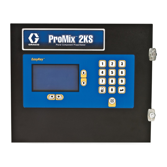
Graco ProMix 2KS Operation
Plural component proportioner
Hide thumbs
Also See for ProMix 2KS:
- Operation manuals (102 pages) ,
- Operation (90 pages) ,
- Repair manual (82 pages)
Table of Contents
Advertisement
Quick Links
Operation
ProMix
Plural Component Proportioner
Automatic system for proportional mixing of plural component coatings, with Wall Mount
Fluid Station or RoboMix Fluid Station. For professional use only.
Approved for use in explosive atmospheres (except the EasyKey).
Important Safety Instructions
Read all warnings and instructions in this
manual. Save these instructions.
Automatic System with Wall Mount Fluid Station
®
2KS
Get other manuals https://www.bkmanuals.com
See pages 4-7 for model information, including maxi-
mum working pressure. Equipment approval labels are
on page 3. Some components shown are not included
with all systems.
Automatic System with RoboMix Fluid Station
TI12553a
0359
312779E
EN
TI12552a
II 2 G
Advertisement
Chapters
Table of Contents
Troubleshooting

Related Manuals for Graco ProMix 2KS


Summary of Contents for Graco ProMix 2KS
- Page 1 Operation ® ProMix 312779E Plural Component Proportioner Automatic system for proportional mixing of plural component coatings, with Wall Mount Fluid Station or RoboMix Fluid Station. For professional use only. Approved for use in explosive atmospheres (except the EasyKey). See pages 4-7 for model information, including maxi- Important Safety Instructions mum working pressure.
-
Page 2: Table Of Contents
Option Screens ......36 Graco Information ......134 Advanced Setup Screens . -
Page 3: Related Manuals
. 1 on page 4 and F . 2 on page 6 for label loca- Manual Description tions. 312778 ProMix 2KS Automatic System EasyKey and Fluid Station Label Installation 312780 ProMix 2KS Automatic System ATEX Certificate is listed here Repair-Parts... -
Page 4: System Configuration And Part Numbers
System Configuration and Part Numbers System Configuration and Part Numbers Wall Mount Fluid Station Configurator Key The configured part number for your equipment is printed on the equipment identification labels. See F for location of the identification labels. The part number includes one digit from each of the following six categories, depending on the configuration of your system. -
Page 5: Standard Features
System Configuration and Part Numbers Hazardous Location Approval Models using a G3000, G3000HR, or intrinsically safe Coriolis meter for both A and B meters are approved for installation in a Hazardous Location - Class I, Div I, Group D, T3 or Zone I Group IIA T3. Maximum Working Pressure Maximum working pressure rating is dependent on the fluid component options selected. -
Page 6: Robomix Fluid Station Configurator Key
System Configuration and Part Numbers RoboMix Fluid Station Configurator Key The configured part number for your equipment is printed on the equipment identification labels. See F for location of the identification labels. The part number includes one digit from each of the following six categories, depending on the configuration of your system. -
Page 7: Standard Features
System Configuration and Part Numbers Hazardous Location Approval Models using a G250 or G250HR for both A and B meters are approved for installation in a Hazardous Location - Class I, Div I, Group D, T3 or Zone I Group IIA T3. Maximum Working Pressure Maximum working pressure rating for RoboMix Systems is 190 psi (1.31 MPa, 13.1 bar). -
Page 8: Accessories
Accessories Accessories Accessory 15V354 Third Purge Valve Kit 15V202 Third Purge Valve Kit 15V536 Solvent Flow Switch Kit 15V213 Power Cable, 100 ft (30.5 m) 15G710 Fiber Optic Cable, 100 ft (30.5 m) 15G614 Flow Control Extension Cable, 40 ft (12.2 m) 15U955 Injection Kit for Dynamic Dosing 15V034 10 cc Integrator Kit 15V033 25 cc Integrator Kit... -
Page 9: Warnings
Warnings Warnings The following warnings are for the setup, use, grounding, maintenance, and repair of this equipment. The exclama- tion point symbol alerts you to a general warning and the hazard symbols refer to procedure-specific risks. When these symbols appear in the body of this manual, refer back to these Warnings. Product-specific hazard symbols and warnings not covered in this section may appear throughout the body of this manual where applicable. - Page 10 Warnings WARNING SKIN INJECTION HAZARD High-pressure fluid from gun, hose leaks, or ruptured components will pierce skin. This may look like just a cut, but it is a serious injury that can result in amputation. Get immediate surgical treatment. • Tighten all fluid connections before operating the equipment.
-
Page 11: Important Two-Component Material Information
Important Two-Component Material Information Important Two-Component Material Information Isocyanate Conditions Moisture Sensitivity of Isocyanates Isocyanates (ISO) are catalysts used in two component coatings. ISO will react with moisture (such as humidity) to form small, hard, abrasive crystals, which become Spraying or dispensing materials containing isocya- suspended in the fluid. -
Page 12: Glossary Of Terms
Glossary of Terms Glossary of Terms Air Chop - the process of mixing air and solvent Ethernet - a method for directly connecting a computer together during the flush cycle to help clean the lines to a network or equipment in the same physical location. and reduce solvent usage. - Page 13 Glossary of Terms Job Total - a resettable value that shows the amount of Purge - when all mixed material is flushed from the sys- material dispensed through the system for one job. A job tem. is complete when a color change or complete system flush occurs.
-
Page 14: Overview
Overview Usage The Graco ProMix 2KS is an electronic two-component paint proportioner. It can blend most two-component solvent and waterborne epoxy, polyurethane, and acid-catalyzed paints. It is not for use with “quick-setting” paints (those with a potlife of less than 15 minutes). - Page 15 Overview Table 1: Component Descriptions Component Description The following optional flow meters are available from Graco: Flow Meters (MA, MB, MS) • G3000 is a general purpose gear meter typically used in flow ranges of 75-3800 cc/min. (0.02–1.0 gal/min.), pressures up to 4000 psi (28 MPa, 276 bar), and viscosi- ties of 20–3000 centipoise.
-
Page 16: Wall Mount System Components
Overview Wall Mount System Components * See the ProMix 2KS Repair-Parts manual for optional cable lengths. TI12553a . 3. Wall Mount System, shown with G3000 Meters, Color/Catalyst Change, Accessory Solvent Meter, and Flow Control 312779E Get other manuals https://www.bkmanuals.com... - Page 17 Overview TI12556b . 4. Wall Mount Fluid Station Key: Component A Meter DVA Component A Dose Valve RVA Component A Sampling Valve SVA Component A Shutoff Valve Component B Meter DVB Component B Dose Valve RVB Component B Sampling Valve SVB Component B Shutoff Valve Solvent Meter (accessory) SPV Solvent Purge Valve...
-
Page 18: Robomix System Components
Overview RoboMix System Components Air Controls Purge Air RoboMix Control Air * See the ProMix 2KS Repair-Parts manual for optional cable lengths. TI12552a . 5. RoboMix System shown with Color/Catalyst Change and Flow Control 312779E Get other manuals https://www.bkmanuals.com... - Page 19 Overview Air Logic In Cable Path B Supply (1/4 npt) A Supply (1/4 npt) Ground Screw Air Purge TI12511b Solvent Supply (1/4 npt) A Dump Out B Dump Out Cover is removed for clarity TI12579b . 6: Details of RoboMix Fluid Station 312779E Get other manuals https://www.bkmanuals.com...
-
Page 20: Easykey Display And Keyboard
EasyKey Display and Keyboard EasyKey Display and Keyboard Keypad LCD Display TI11630A Navigation Keys Alarm Reset Key . 7. EasyKey Display and Keypad Display Table 2: EasyKey Keypad Functions (see F . 7) Shows graphical and text information related to setup Function and spray operations. -
Page 21: Ac Power Switch
Clear by pressing the Alarm Reset key. ➜ Restore setup password See manual 313386 for more information. NOTE: If using the Graco Gateway in your system, dis- connect its cable from the EasyKey before updating the ProMix 2KS software. Ethernet Connection You can access data on an office or industrial network through the internet with the proper configuration. -
Page 22: Run Mode Screens
. 11 for a map of the Run screens. Detailed screen descriptions follow. Splash Screen At power up, the Graco logo and software revision will display for approximately 5 seconds, followed by the Status Screen (see page 24). . 9. Splash Screen The Splash screen will also momentarily display “Estab-... - Page 23 Run Mode Screens Press the Setup key to enter Setup mode. TI12802a . 11. Run Screens Map 312779E Get other manuals https://www.bkmanuals.com...
-
Page 24: Status Screen
Run Mode Screens Status Screen Target Flow Rate and Current Flow Rate: in cc/min. • Use the Up or Down keys to scroll through the Run screens. Animation: when the gun is triggered, the gun appears to spray and the component A or B hose lights up, showing which component dose valve is •... -
Page 25: Manual Override Screen
Run Mode Screens Manual Override Screen Flow Rate Range This screen displays the flow rate range selected on Advanced Setup Screen 5 (see page 41). Flow Set Point The Flow Set Point is user settable. If Flow Control Override is set to “Off” or “Pressure” in Advanced Setup Screen 1 on page 39, the Flow Set Point will dis- play as cc/min. -
Page 26: Totals Screen
Run Mode Screens Global Flow Control Data Copy Reset Total Screen This field allows you to copy flow control data from the active recipe to all recipes. Press the Enter key to view the menu, then select Start or Abort. See F . -
Page 27: Alarms Screen
Run Mode Screens Alarms Screen See F . 22. If the tank volume reaches the low-level threshold, the EasyKey screen will display the Tank Level Low alarm and prompt the user to do one of the following: 1. Refill tank volume to clear the alarm. 2. -
Page 28: Setup Mode
Setup Mode Setup Mode NOTE: See F . 23 for a map of the Setup screens. Press the Setup key to enter Setup mode. Detailed screen descriptions follow. Press the Setup key to enter Setup mode. This screen appears only if a password is activated. -
Page 29: Password Screen
Setup Mode Password Screen Set Up Home Screen If a password has been activated (see Configure Screen 1, page 32), the Password screen will appear. You must enter the password to access the Set Up Home Screen. Entering the wrong password returns the display to the Status Screen. - Page 30 Setup Mode Table 3: Component Software Versions Display (may vary from examples Component shown) Description EK (EasyKey) 2.00.012 EasyKey software version. FP (Fluid Plate) 2.00.012 Fluid Plate software version. BC (Booth Control) Booth Control not installed, not detected, or not oper- ational.
-
Page 31: System Configuration Screens
Setup Mode System Configuration Screens NOTE: See F . 27 for a map of the System Configura- NOTE: Each screen displays the current screen number tion Screens. Detailed screen descriptions follow. and the total number of screens in the group. TI12804a . - Page 32 Setup Mode Configure Screen 1 Configure Screen 2 . 29. Configure Screen 2 . 28. Configure Screen 1 Month Language Enter current month. Defines the language of the screen text. Select English (default), Spanish, French, German, Italian, Dutch, Jap- anese (Kanji), Korean, and Chinese (Simplified). Enter current day.
- Page 33 Setup Mode Configure Screen 3 Configure Screen 4 . 31. Configure Screen 4 . 30. Configure Screen 3 Dose Size Run Mode Select the total dose size (cc) from the pulldown menu: Select the Run mode application from the pulldown 100, 50, 25, 10, or select DD to turn on dynamic dosing.
- Page 34 Setup Mode DD Setup Mode Configure Screen 5 See F . 32 and F . 33. Selecting “DD” makes the Dynamic Dosing Setup mode field appear. Select On to enable DD setup mode, or Off to disable. See page 86 for further information.
- Page 35 Displays AFS if Number of Guns is set to “2” in Config- ure Screen 4, page 33. Control Network ID Used for the Graco Gateway network system. See Graco Gateway manual 312785 for further information 312779E Get other manuals https://www.bkmanuals.com...
-
Page 36: Option Screens
Setup Mode Option Screens Verification Screen NOTE: See F . 27 on page 31 for a map of the Option Screens. Detailed screen descriptions follow. NOTE: Each screen displays the current screen number and the total number of screens in the group. Option Screen 1 . - Page 37 Setup Mode Option Screen 2 . 38. Option Screen 2 External Color Change If set to “Off”, Color/Catalyst Purge Time and Color/Cat- alyst Fill Time appear in Advanced Setup Screen 1, page 39 or Recipe Setup Screen 2, page 44 (depend- ing on whether Flush and Fill Inputs are set to “Global”...
-
Page 38: Advanced Setup Screens
Setup Mode Advanced Setup Screens NOTE: See F . 39 for a map of the Advanced Setup Screens. Detailed screen descriptions follow. Advanced Setup screens 2, 3, 4, and 8 appear depending on selections made in Option screens 1 and 2. Screen 5 appears if Flow Control is set to “On”... - Page 39 Setup Mode NOTE: Each screen displays the current screen number Manual Override and the total number of screens in the group. The total This field only appears if Run Mode is set to “Automatic” number of screens in a group and the fields displayed or “Semi-automatic”...
- Page 40 Setup Mode Advanced Setup Screen 2 Advanced Setup Screen 3 . 42. Advanced Setup Screen 2 . 43. Advanced Setup Screen 3 This screen appears only if Flush and Fill Input is set to “Global” in Option Screen 1, page 36. This screen appears only if Flush and Fill Input is set to “Global”...
- Page 41 Setup Mode Advanced Setup Screen 4 Advanced Setup Screen 5 . 45. Advanced Setup Screen 5 (Automatic Mode . 44. Advanced Setup Screen 4 with Flow Control Only) This screen appears only if K-factor Input is set to This screen appears only if Flow Control is set to “On” in “Global”...
- Page 42 Setup Mode Advanced Setup Screen 6 Advanced Setup Screen 8 . 46. Advanced Setup Screen 6 . 48. Advanced Setup Screen 8 This screen shows the status of recipe analog inputs This screen appears only if Flush and Fill Input is set to and digital outputs.
-
Page 43: Recipe Setup Screens
Setup Mode Recipe Setup Screens NOTE: See F . 49 for a map of the Recipe screens. Detailed screen descriptions follow. Recipe 0 Screens Recipe screens 3, 4, 5, 6, and 7 appear depending on selections made in Option screens 1 and 2 TI12806a . - Page 44 Setup Mode NOTE: Each screen displays the current screen number Recipe Setup Screen 2 and the total number of screens in the group. The total number of screens in a group and the fields displayed on each screen may vary depending on selections made in the System Configuration Screens and Option Screens.
- Page 45 Setup Mode Recipe Setup Screen 3 Recipe Setup Screen 4 . 53. Recipe Setup Screen 4 . 52. Recipe Setup Screen 3 This screen appears only if Flush and Fill Input is set to This screen appears only if Flush and Fill Input is set to “Recipe”...
- Page 46 Setup Mode Recipe Setup Screen 5 Recipe Setup Screen 6 . 55. Recipe Setup Screen 6 . 54. Recipe Setup Screen 5 This screen appears only if Flow Rate Monitor is set to This screen appears only if K-factor Input is set to “Rec- “On”...
-
Page 47: Recipe 0 Screens
Setup Mode Recipe 0 Screens NOTE: See F . 49 on page 43 for a map of the Recipe Final Purge Source 0 screens. Detailed screen descriptions follow. Select “Air,” “Solvent,” or “3rd Flush Valve” (available only if 3rd Flush Valve is set to “On” in Configure Recipe 0 is typically used: Screen 3 on page 33). - Page 48 Setup Mode Recipe 0 Screen 3 Recipe 0 Screen 4 . 60. Recipe 0 Screen 4 . 59. Recipe 0 Screen 3 This screen appears only if Flush and Fill Input is set to “Recipe” in Option Screen 1, page 36 and Special Out- This screen only appears if Solvent Monitor is set to puts is set to 1, 2, 3, or 4 in Configure Screen 5, page “Meter”...
-
Page 49: Calibration Screen
Setup Mode Calibration Screen . 61. Calibration Screen Use this screen to calibrate a meter. Set to “Meter A,” “Meter B,” or “Solvent Meter” (available if Solvent Moni- tor in Configure Screen 5, page 34, is set to “Meter”). • Start - start calibration •... - Page 50 Setup Mode 312779E Get other manuals https://www.bkmanuals.com...
-
Page 51: Promix 2Ks Integration Specifics
Discrete I/O Communications Discrete I/O requires a 24 Vdc power supply which must be supplied on site. The ProMix 2KS does not supply The ProMix 2KS Automatic system does not use a power for Discrete I/O. Booth Control. Instead, it uses Discrete I/O or Network Communications to drive the system. - Page 52 Idle mode after 2 minutes of inactivity. minimum. When recognized by the ProMix 2KS it clears When a Gun Trigger input is seen, the ProMix 2KS will any active alarms and allows the automation to take the automatically leave Idle mode and resume mixing mate- next step.
- Page 53 ProMix 2KS Integration Specifics Digital Output Common/Power Flow Rate Alarm Output Flow Control Calibrate Active Fill Active Mix Ready Output Mix Active Output Purge/Recipe Change Active Output Digital Output Common/Power Recipe Change Input Recipe Bit 5 Input Recipe Bit 4 Input...
- Page 54 Green Gateway manual 312785.) Alarm Reset Brown Mix_Ready: This output will remain High while there are Outputs (Automation Sourcing) no alarms and the ProMix 2KS is ready to go to Mix Alarm Output Blue mode. Digital Out Common Orange General Alarm: This output will remain High when any...
-
Page 55: Automation Flow Charts
Recipe 0 or a valid recipe number (1-60). ProMix 2KS in Mix Mode (Complete) Mix Active = 1 while the ProMix 2KS is in Mix mode . 65. Start Mix Mode Process Flow Chart 312779E Get other manuals https://www.bkmanuals.com... - Page 56 ProMix 2KS Integration Specifics Mixing Mode Process See F . 66, Table 5, and Table 6. Mixing Mode Process Mixing Mode is desired. PLC is polling to ensure Mixing Mode is main- tained. Is Mix Active bit = 1? Mixing Process active...
- Page 57 ProMix 2KS Integration Specifics Purge Mode Process See F . 67, Table 5, and Table 6. Start Is Mix Ready bit = 1? Must be Alarm Condition or Active Recipe 61. See Alarm Processing Set Purge bit = 1? on page 59, or Startup from Recipe 61 (see NOTE below).
- Page 58 ProMix 2KS Integration Specifics Color Change Mode Process See F . 68, Table 5, and Table 6. Color Change Process (basic) Do nothing. Is Active Recipe = Spraying at to desired recipe? desired recipe. (Register 40005). Load ccNewRecipe (Register 40046) with...
- Page 59 ProMix 2KS Integration Specifics Alarm Processing See F . 69, Table 5, Table 6, and Table 7. Alarm Processing An Alarm Condition has been found previously. Alarm_General = 1. Check if Potlife Alarm: is Alarm_ Potlife bit = 1? Two options:...
- Page 60 ProMix 2KS Integration Specifics Table 5: ProMix 2KS Digital Inputs (Modbus Register 40040) Digital Input Binary Name Details 0 0 0 0 0 0 0 0 0 0 X X X X X X Recipe Binary bits for viewing discrete inputs only.
- Page 61 ProMix 2KS Integration Specifics Table 6: ProMix 2KS Digital Outputs (Modbus Register 40041) Digital Input Binary Name Details 0 0 0 0 0 0 0 0 0 0 0 0 0 0 0 1 Purge_CC_Active “1” indicates Purge or Color Change is in prog-...
- Page 62 ProMix 2KS Integration Specifics Table 7: ProMix 2KS Active Alarms (Modbus Register 40010) Digital Input Binary Name Details Low Byte: 0 0000 0000 0000 0000 No Bits Set No Active Alarms Low Byte: 0 0000 0000 0000 0001 Comm_Error Low Byte: 0...
- Page 63 ProMix 2KS Integration Specifics ProMix 2KS EasyKey PLC Output Digital Input (Sourcing) Input Output Common Input Common ProMix 2KS EasyKey PLC Input Digital Output (Sinking) Output Common Input Output Common ProMix 2KS EasyKey PLC Input Digital Output (Sourcing) Output Input...
- Page 64 ProMix 2KS Integration Specifics Table 8: Discrete I/O Terminal Connections Terminal Terminal Location Name Details (also see pages 60 and 61) Digital Inputs J2, Remote I/O Board Set Bit to Initiate Mix Mode (maintain) J2, Remote I/O Board Purge Set Bit to “1” to initiate Purge Sequence...
-
Page 65: Potlife_Alarm
ProMix 2KS Integration Specifics Table 8: Discrete I/O Terminal Connections Terminal Terminal Location Name Details (also see pages 60 and 61) Digital Outputs 1★ J4, Remote I/O Board Digital Output Common/Power J4, Remote I/O Board Purge_CC Active “1” Indicates Purge or Color Change is in... - Page 66 ProMix 2KS Integration Specifics Table 9: ProMix 2KS Recipe Bits Recipe Bits Number Recipe Bits Number 312779E Get other manuals https://www.bkmanuals.com...
-
Page 67: Integrated Flow Control
Integrated Flow Control Integrated Flow Control Flow Control Description Air-operated Fluid Pressure Flow control is an optional feature which incorporates an Fluid Regulator Gauge Port intrinsically safe regulator control module with the Pro- Fluid Pressure Mix 2KS automatic system. Flow control precisely regu- Sensor lates the flow of material to a manual or automatic air 1/8 npt(f) -
Page 68: Fluid And Air Pressure Requirements
Integrated Flow Control Fluid and Air Pressure Flow Control Operation Requirements See F . 73 for module 249849 and F . 74 for module 24H989. The Flow Control System includes two infor- The fluid input pressure to the fluid regulator must be mation loops: high enough to provide a 15-20 psi (0.1-0.14 MPa, 1.0-1.4 bar) pressure differential across the regulator at... - Page 69 Regulator Air Line V/P (Voltage/Air Pressure) Valve Pressure Input: Feedback from Fluid Pressure Sensor TI17118a . 73. ProMix 2KS Flow Control Schematic Diagram (249849 Module) Air-operated Remote Fluid Regulator Mixed Material Line Flow Input: Feedback from Meters A and B...
-
Page 70: Flow Control Operating Process Example
ProMix A discrete signal is 0-10Vdc, which corresponds linearly 2KS. The ProMix 2KS adjusts the voltage to the V/P to to the set operating range. For example, if the set range maintain the actual flow. - Page 71 Analog Signal to V/P Air Line V/P (Voltage/Air Pressure) Valve Step 2: Pressure Input TI17118a . 75. ProMix 2KS Flow Control Pressure Loop and Flow Loop (249849 Module) Step 3: Flow Input Step 1: ProMix 2KS Fluid Pressure receives a...
-
Page 72: Flow Control Setup
2. In Advanced Setup Screen 1, turn Manual Over- inputs. ride On. The Flow Control Override field will appear. NOTE: See the Graco Gateway manual for Flow Control Modbus addresses. 5. See Flow Control Startup. . 78. Advanced Setup Screen 1 312779E Get other manuals https://www.bkmanuals.com... - Page 73 Integrated Flow Control 3. Set Flow Control Override to % Open. See F . 79 4. On the Manual Override Screen, drive the regula- and Table 10. On the Manual Override Screen, the tor to a percentage open that starts fluid flow. Fluid Flow Set Point field will display as a percentage pressure should be above 12 psi (.08 MPa, 0.84 open (see F...
-
Page 74: Flow Control Calibration
Integrated Flow Control Flow Control Calibration Flow Control Calibration is an automatic routine that 3. Go to Advanced Setup Screen 1 (see F . 83). establishes a pressure vs flow profile between low and Turn Manual Override On. high operating points. See F . - Page 75 Integrated Flow Control 5. Return to the Status Screen (see F . 85). The sta- 8. When calibration is complete, the Status Screen tus bar at the bottom of the screen will indicate that will change from Mix Calibration to Mix. The unit should have built a complete table for the flow rate Mix Calibration is in progress.
- Page 76 Integrated Flow Control Global FC Data Copy Setting Ki and Kp Set Global FC Data Copy to Start on the Manual Over- . 89 shows the definition and relationship between Ki ride Screen (see F . 87). Global copy provides a start- and Kp.
-
Page 77: Pressure Flow Control Mode
Integrated Flow Control Pressure Flow Control Mode This mode may be used with a ProMix 2KS connected both to a robot with flow control and to a manual gun. Because there are two flow paths, the meters cannot be When the Flow Control Override is set to “Pressure”, the used to close the flow loop. -
Page 78: Flow Control Troubleshooting
Integrated Flow Control Flow Control Troubleshooting Problem: Flow Command does not produce fluid output. Test the system as follows, to determine if the problem is mechanical or electrical. 1. Install a 0-100 psi (0-0.7 MPa, 0-7.0 bar), 1/8 npt(m) air pressure gauge (not supplied) as follows. a. - Page 79 Integrated Flow Control Result of the Test Cause Solution Gauge reading increases and The problem is mechanical: 1. Clear any clogs. decreases as % Open value is • restriction/plugged hose 2. Remove restrictions. changed and fluid flow does not change or is not present. 3.
-
Page 80: System Operation
System Operation System Operation Operation Modes System mixes and dispenses material (apply Mix input). Standby Stops the system (remove Mix input). Purge Purges the system, using air and solvent (apply Purge input). Sequential Dosing Components A and B dispense sequentially in the nec- essary volumes to attain the mix ratio. -
Page 81: Typical Plc Interaction With Promix 2Ks
Network Communications or Discrete I/O. NOTE: The Gun Trigger input has the same effect as the air flow switch used on manual ProMix 2KS sys- tems. 312779E Get other manuals https://www.bkmanuals.com... - Page 82 Job_Complete Input Every time a momentary Job_Complete input is seen by the ProMix 2KS, a job log will be recorded, logging the A and B meter volumes (cc) with a time and date stamp. The volumes will then be reset to 0. (Volume totals are accumulated since the last reset.)
-
Page 83: General Operating Cycle, Sequential Dosing
2. The system enters Mix mode to begin operation. ProMix 2KS controller. 3. The ProMix 2KS controller sends signals to activate When the target volume is dispensed, Dose the solenoid valves. The solenoid valves activate Valve B closes. - Page 84 System Operation TI12556b Key: Component A Meter SVB Component B Shutoff Valve DVA Component A Dose Valve Solvent Meter (accessory) RVA Component A Sampling Valve SPV Solvent Purge Valve SVA Component A Shutoff Valve APV Air Purge Valve Component B Meter Static Mixer DVB Component B Dose Valve Fluid Integrator...
-
Page 85: General Operating Cycle, Dynamic Dosing
System Operation General Operating Cycle, Dynamic Dosing Overview Dynamic Dosing System Parameters Dynamic Dosing provides on-demand proportioning, The following parameters affect dynamic dosing perfor- eliminating the need for an integrator and therefore min- mance: imizing undesired material contact. This feature is espe- cially useful with shear-sensitive and waterborne •... - Page 86 Install the 15U955 Injection Kit in the fluid manifold as To enable DD setup mode, select On in the DD explained in the ProMix 2KS Installation manual. Use Setup mode drop down menu. This disables Off the charts provided in that manual to select an appropri-...
- Page 87 System Operation Balancing A/B Pressure If component B pressure is too high, it will push the com- B Pressure ponent A stream aside during B injection. The valve will Too Low not open long enough, causing a High Ratio alarm. If component B pressure is too low, it will not be injected B Pressure Too High...
-
Page 88: Mix Manifold Valve Settings
System Operation Table 12: Dynamic Dosing Troubleshooting Guide (for complete system troubleshooting, see Table 17 beginning on page 116) Warning/Alarm Message Solution B Pressure Too Low (see F . 96) • Increase B pressure. • Clean restrictor or use a larger size. •... -
Page 89: Start Up
System Operation ➜ Graco logo, software revision, and “Establishing Start Up Communication” will display, followed by Status screen. See page 22. 1. Go through the Pre-Operation Checklist in Table 14. ➜ At power up the system defaults to Recipe 61, Table 14: Pre-Operation Checklist which is not a valid recipe number. - Page 90 System Operation 10. Purge air from the fluid lines. Watch the fluid flow rate displayed on the Status screen while the gun is fully open. Verify that the a. Shut off air to the gun by clos- flow rate of components A and B are within 10% of ing the air regulator or shutoff each other.
-
Page 91: Shutdown
Pressure Relief Procedure NOTE: The following procedures relieve all fluid and air Overnight Shutdown pressure in the ProMix 2KS system. Use the procedure 1. Leave the power on. appropriate for your system configuration. 2. Run Recipe 0 to purge solvent through meters and gun. - Page 92 System Operation Systems with Color Change and without Systems with Color/Catalyst Change and Dump Valves Dump Valves NOTE: This procedure relieves pressure through the NOTE: This procedure relieves pressure through the sampling valve. dump valves. 1. Complete all steps under Single Color Systems, 1.
- Page 93 System Operation RoboMix Fluid Station Dose Valve B Override Button Dose Valve A Override Button TI12655a Wall Mount Fluid Station Power Fiber Optic Dose A Valve Overrides Dose B Dump Valve A Dump Valve B Optional Solenoid GFB 1 Locations GFB 2 3rd Purge Valve Dose Valve A...
- Page 94 System Operation Solenoid Solenoid Identification Identification Label Label TI12826a Solvent Solenoid Overrides . 105: Color Change Solenoids Key: Component A Meter DVA Component A Dose Valve RVA Component A Sampling Valve SVA Component A Shutoff Valve Component B Meter DVB Component B Dose Valve RVB Component B Sampling Valve...
-
Page 95: Purging
System Operation Purging 2. Set the solvent supply pressure regulator at a pres- sure high enough to completely purge the system in a reasonable amount of time but low enough to avoid splashing or an injection injury. Generally, a setting of 100 psi (0.7 MPa, 7 bar) is sufficient. 3. - Page 96 System Operation Purging Using Recipe 0 Purging Fluid Supply System Recipe 0 is typically used: Follow this procedure before: • in multiple color systems to purge out material lines • the first time material is loaded into equipment* without loading a new color •...
- Page 97 System Operation 3. Adjust the solvent fluid supply pressure. Use the lowest possible pressure to avoid splashing. 4. Remove the Fluid Station cover to access the sole- noid valves. See F . 104 on page 93. 5. Purge as follows: •...
- Page 98 System Operation Purging Sampling Valves and Tubes 7. To avoid splashing, slowly open the sampling valves and dispense solvent until the valves and Follow this procedure after meter calibration. tubes are clean. 1. Go to Standby mode (remove Mix input). NOTE: When performing a calibration purge, the solvent valve(s) close automatically after 2 minutes 2.
-
Page 99: Solvent Push Feature
Solvent Push requires an accessory solvent meter (MS). Standby key. The Solvent Purge Valve (SPV) or Order Graco Part No. 280555 S3000 Solvent Meter Kit. See manual 308778. 3rd purge valve will close. To re-enter Solvent Push, 1. See F . -
Page 100: Meter Calibration
Meter Calibration Meter Calibration 4. Place the beakers (minimum size - 250 cc) in hold- ers. Put the sampling tubes into the beakers. (Wall Mount Fluid Station only.) NOTE: If tubes need replacing, use 5/32 in. or 4 mm OD tubing. To avoid splashing fluid in the eyes, wear eye protec- tion. - Page 101 8. Dispense component A or B into beaker. 12. After the volume for A, B, or Solvent is entered, the ProMix 2KS controller calculates the new flow meter K-factor and shows it on the Calibration Screen. NOTE: K-factor values on the screen are viewable only.
-
Page 102: Color Change
Color Change Color Change Color Change Procedures Color Change Sequences . 109 through F . 126 illustrate various color change Multiple Color Systems sequences. See Table 15 to determine which figure to reference, based on the recipe change and system con- 1. - Page 103 Color Change Color Purge/Dump First Purge Step M0-M1 Step P0-P1 Select the First Purge Source (air, solvent, or 3rd valve) • This sequence flushes out the color with solvent, and First Purge Time. For most applications, air is from the color valve to the Dump A valve. selected.
- Page 104 Color Change Table 15: Color Change Chart Reference Number of Starting Ending Color Catalyst Dump 3rd Purge Gun Flush Recipe Recipe Change Change Valves Valve Boxes Refer to Fig. . 110 . 109 . 112 0, 1, or 2 . 111 0, 1, or 2 .
- Page 105 Color Change ProMix 2KS Recipe Change Chart 1: A1 to A2, B1 to B2 with Dump Valves Valve Time-Sequence Dump A Dump B Color Change Solvent Catalyst Change Solvent Color Change A Catalyst Change B Color Purge Time P0->P1 Color Fill Time P1->P2 Catalyst Purge Time P2->P3...
- Page 106 Color Change ProMix 2KS Recipe Change Chart 3: A1 to A2, same B with Dump Valves Valve Time-Sequence Dump A Dump B Color Change Solvent Catalyst Change Solvent Color Change A Catalyst Change B Color Purge Time P0->P1 Color Fill Time P1->P2 CC Purge/Fill Timers are independent of Mixed Material Purge Timers.
- Page 107 Color Change ProMix 2KS Recipe Change Chart 5: B1 to B2, same A with Dump Valves Valve Time-Sequence Dump A Dump B Color Change Solvent Catalyst Change Solvent Color Change A Catalyst Change B Catalyst Purge Time P0->P1 Catalyst Fill Time P1->P2 CC Purge/Fill Timers are independent of Mixed Material Purge Timers.
- Page 108 Color Change ProMix 2KS Recipe Change Chart 7: A1 to A2, B1 to B2 with Dump Valves, 1 GFB Valve Time-Sequence Dump A Dump B Color Change Solvent Catalyst Change Solvent Color Change A Catalyst Change B Color Purge Time P0->P1 Color Fill Time P1->P2...
- Page 109 Color Change ProMix 2KS Recipe Change Chart 9: A1-A2, same B without Dump Valves, 1 GFB Valve Time-Sequence Dump A Dump B Color Change Solvent Catalyst Change Solvent Color Change A Catalyst Change B Air Chop Time Solvent Chop Time...
- Page 110 Color Change ProMix 2KS Recipe Change Chart 11: Recipe 0 OR 61 to Recipe X with Dump Valves Valve Time-Sequence Dump A Dump B Color Change Solvent Catalyst Change Solvent Color Change A Catalyst Change B Air Purge Solvent Purge...
- Page 111 Color Change ProMix 2KS Recipe Change Chart 13: Recipe 0 OR 61 to Recipe X without Dump Valves Valve Time-Sequence Dump A Dump B Color Change Solvent Catalyst Change Solvent Color Change A Catalyst Change B Air Purge Solvent Purge...
- Page 112 Color Change ProMix 2KS Recipe Change Chart 15: Same A, Same B Valve Time-Sequence Dump A Dump B Color Change Solvent Catalyst Change Solvent Color Change A Catalyst Change B Air Chop Time Solvent Chop Time First Purge (one of these)
- Page 113 Color Change ProMix 2KS Recipe Change Chart 17: Recipe 0 OR 61 to Recipe X with Dump Valves and 3rd Flush Valve Valve Time-Sequence Dump A Dump B Color Change Solvent Catalyst Change Solvent Color Change A Catalyst Change B...
- Page 114 Color Change 312779E Get other manuals https://www.bkmanuals.com...
-
Page 115: Alarms And Warnings
They are saved in Alarm the date/time stamped log, which can be viewed on a E-13 High Flow Alarm Page 122 PC, using the ProMix 2KS Web Interface (see manual E-14 Low Flow Alarm Page 122 313386). E-15 System Idle Warning... -
Page 116: Alarm Troubleshooting
Alarm Troubleshooting Alarm Troubleshooting Table 17. Alarm Troubleshooting E-1: COMM ERROR Cause Solution No power to the EasyKey. Connect power to EasyKey. No power to Fluid Station. The intrinsically safe power Verify that the cable is correctly connected. See Installa- cable between the EasyKey and Fluid Station is not con- tion manual. -
Page 117: Ratio_High_Alarm
Slow actuation of the component A or B valves. This can Manually operate the Dispense A and B solenoid valves be caused by: as instructed in the ProMix 2KS Repair-Parts manual to check operation. • Air pressure to the valve actuators is too low. -
Page 118: Ratio_Low_Alarm
Slow actuation of the component A or B valves. This can Manually operate the Dispense A and B solenoid valves be caused by: as instructed in the ProMix 2KS Repair-Parts manual to check operation. • Air pressure to the valve actuators is too low. - Page 119 (such as fans and conveyors). 3. Check if the ProMix 2KS is reading any fluid flow. 4. If the ProMix 2KS shows there is fluid flow and there are no leaks from the gun or any other seals or fit- tings, the flow meters are probably being affected by pressure pulsations.
- Page 120 Alarm Troubleshooting Table 17. Alarm Troubleshooting E-7: DOSE TIME A ALARM and E-8: DOSE TIME B ALARM E-7: gun trigger input is active (AFS or Integration) and no A meter pulses are detected during the dose time selected. E-8: gun trigger input is active (AFS or Integration) and no B meter pulses are detected during the dose time selected.
-
Page 121: Mix_In_Setup_Alarm
E-11: PURGE VOLUME ALARM Cause Solution ProMix 2KS solvent flow switch is not activated while Verify that the gun is not shut off and that the solvent flow purging. switch is activated while purge is taking place. Minimum flush volume is not achieved. -
Page 122: Can_Comm_Error_Alarm
Alarm Troubleshooting Table 17. Alarm Troubleshooting E-12: CAN COMM ERROR ALARM Cause Solution Communication between the Color Change Module and • Verify that all cables are connected securely and that the Fluid Station is interrupted. the Color Change power LED turns on. If the power LED does not turn on, the problem is probably caused by a bad connection. - Page 123 Alarm Troubleshooting Table 17. Alarm Troubleshooting E-15: SYSTEM IDLE WARNING Cause Solution Mix input is high, but the gun has not been triggered for 2 If not painting, clear alarm and resume operation. minutes. If painting, shut down and inspect fluid meter. E-16: SETUP CHANGE WARNING Cause Solution...
- Page 124 Alarm Troubleshooting Table 17. Alarm Troubleshooting E-19: I/O ALARM Cause Solution The Mix and Purge digital inputs are on at the same time. Ensure that only one input is on at a time. At least 1 sec delay is required when switching from Mix to Purge or vice versa.
-
Page 125: Material_Fill_Alarm
Alarm Troubleshooting Table 17. Alarm Troubleshooting E-20: PURGE INITIATE ALARM Cause Solution System detects atomizing air to the gun when purge is Shut off gun air. selected. For systems with a gun flush box, gun is not in the box Place gun in gun flush box. -
Page 126: Color/Catalyst_Purge_Alarm
Alarm Troubleshooting Table 17. Alarm Troubleshooting E-25: AUTO DUMP COMPLETE ALARM Cause Solution A potlife alarm is active for more than 2 minutes, the gun Be sure to spray all mixed material before potlife expires. flush box is enabled and gun is in the gun flush box, and an auto dump flush sequence is complete. -
Page 127: Schematic Diagrams
Schematic Diagrams Schematic Diagrams System Pneumatic Schematic COLOR COLOR VALVE CHANGE STACKS CONTROL AIR EXHAUST MUFFLER MANIFOLD COLOR 1 COLOR 2 12 VDC COLOR 3 COLOR 4 DOSE A VALVE 4-WAY SOLENOID COLOR 5 COLOR 6 COLOR 7 COLOR 8 12 VDC COLOR SOLVENT DOSE B... -
Page 128: System Electrical Schematic
Schematic Diagrams System Electrical Schematic NOTE: The electrical schematic illustrates all possible wiring expansions in a ProMix 2KS system. Some compo- nents shown are not included with all systems. Non-Hazardous Area NON-HAZARDOUS AREA OPERATOR INTERFACE LINE FILTER DC OK 85-250 VAC... - Page 129 Schematic Diagrams System Electrical Schematic NOTE: The electrical schematic illustrates all possible wiring expansions in a ProMix 2KS system. Some compo- nents shown are not included with all systems. Hazardous Area HAZARDOUS AREA FLUID PANEL CONTROL BOX 3X CABLE FLUID...
-
Page 130: Easykey Electrical Schematic
Schematic Diagrams EasyKey Electrical Schematic 312779E Get other manuals https://www.bkmanuals.com... -
Page 131: Meter Performance Data (G3000 On A And B)
Meter Performance Data (G3000 on A and B) Meter Performance Data (G3000 on A and B) 312779E Get other manuals https://www.bkmanuals.com... -
Page 132: Meter Performance Data (G3000 On A, Coriolis On B)
Meter Performance Data (G3000 on A, Coriolis on B) Meter Performance Data (G3000 on A, Coriolis on B) 312779E Get other manuals https://www.bkmanuals.com... -
Page 133: Technical Data
Air filtration for air logic and purge air (Graco-supplied)......5 micron (minimum) filtration required; clean and dry air Air filtration for atomizing air (user-supplied) . -
Page 134: Graco Standard Warranty
With the exception of any special, extended, or limited warranty published by Graco, Graco will, for a period of twelve months from the date of sale, repair or replace any part of the equipment determined by Graco to be defective.
Need help?
Do you have a question about the ProMix 2KS and is the answer not in the manual?
Questions and answers