Graco Therm-O-Flow 200 Instructions Manual
Bulk hot melt system
Hide thumbs
Also See for Therm-O-Flow 200:
- Instructions - parts manual (152 pages) ,
- Instructions-parts list manual (118 pages) ,
- Instructions-parts list manual (109 pages)
Table of Contents
Advertisement
Quick Links
Instructions
200 Liter (55 Gallon) Drum Size
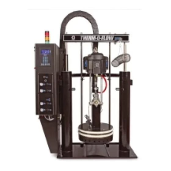
Therm-O-Flow 200
™
EasyKey
Hot Melt Drum Unloaders
For applying hot melt sealant and adhesive materials.
For professional use only. Not approved to European explosive atmosphere requirements.
Maximum Operating Temperature (All Models): 400°F (204°C)
NXT 2200 Powered Unloaders, Models A-1 and A-4
2300 psi (15.9 MPa, 159 bar) Maximum Fluid Working Pressure
125 psi (0.85 MPa, 8.5 bar) Maximum System Air Pressure (Ram)
100 psi (0.7 MPa, 7 bar) Maximum Air Motor Pressure
NXT 3400 Powered Unloaders, Models A-2 and A-5
3000 psi (20.7 MPa, 207 bar) Maximum Fluid Working Pressure
125 psi (0.85 MPa, 8.5 bar) Maximum System Air Pressure (Ram)
82 psi (0.57 MPa, 5.7 bar) Maximum Air Motor Pressure
NXT 6500 Powered Unloaders, Models A-3 and A-6
3000 psi (20.7 MPa, 207 bar) Maximum Fluid Working Pressure
125 psi (0.85 MPa, 8.5 bar) Maximum System Air Pressure (Ram)
43 psi (0.29 MPa, 2.9 bar) Maximum Air Motor Pressure
Important Safety Instructions.
Read all warnings and instructions in this manual.
Save these instructions.
See page 2 for Contents.
®
TI7936-lr
311208P
EN
Advertisement
Table of Contents
Troubleshooting

Related Manuals for Graco Therm-O-Flow 200


Summary of Contents for Graco Therm-O-Flow 200
- Page 1 Instructions 200 Liter (55 Gallon) Drum Size ® Therm-O-Flow 200 311208P ™ EasyKey Hot Melt Drum Unloaders For applying hot melt sealant and adhesive materials. For professional use only. Not approved to European explosive atmosphere requirements. Maximum Operating Temperature (All Models): 400°F (204°C) NXT 2200 Powered Unloaders, Models A-1 and A-4 2300 psi (15.9 MPa, 159 bar) Maximum Fluid Working Pressure...
-
Page 2: Table Of Contents
Alarm Troubleshooting ..... 40 Graco Information ......98... -
Page 3: Warnings
Read fluid and solvent manufacturer’s warnings. For complete information about your material, request MSDS from distributor or retailer. • Check equipment daily. Repair or replace worn or damaged parts immediately with genuine Graco replacement parts only. • Do not alter or modify equipment. - Page 4 Warnings WARNING PERSONAL PROTECTIVE EQUIPMENT You must wear appropriate protective equipment when operating, servicing, or when in the operating area of the equipment to help protect you from serious injury, including eye injury, inhalation of toxic fumes, burns, and hearing loss. This equipment includes but is not limited to: •...
- Page 5 Warnings 311208P...
-
Page 6: Overview
Overview Overview How the Therm-O-Flow 200 Works 1. Motor 2. Heated Platen A heated platen melts the sealant or adhesive and 3. Follower Seals directs the molten material to the pump inlet. The mate- 4. Drum Ram rial then travels through a heated Check–Mate pump 5. - Page 7 Overview None Code M Type of Hose Connection Manual gun bottom feed with Swirl & .030 orifice None Manual gun top feed with Swirl & .030 orifice Single hose and end-of-hose device 243694 with Swirl & .030 orifice Dual hose and end-of-hose device from tee kit 244909 with Swirl &...
-
Page 8: Component Identification
• Air motor Air Supply Hose connects the air regulator to the air motor. The Therm-O-Flow 200 has 6 or 8 heat zones. Zones 1 and 2 are always used for the heated drum platen and Pneumatic Control Panel the heated pump. Zones 3 and 4, 5 and 6, and 7 and 8 are each available as paired zones through 16-pin con- The pneumatic control panel includes the following. - Page 9 Overview Component Identification TI8134A TI7936A TI8158A . 1: Component Identification Key: System Master Air Valve (bleed-type) Ram Up Air Regulator Air Line Filter Ram Down Air Regulator Air Motor Air Regulator (bleed-type) Ram Up/Down Lever Air Motor Master Air Valve (bleed-type) Platen Blow-off Valve Blow-Off Air Regulator Heated Pump...
-
Page 10: Typical Installation
See F . 2. Contact your Graco distrib- tion system. utor for help in designing a system to suit your particular needs. - Page 11 Typical Installation Typical Installation (Advanced Unit Shown) 204 Air Motor Remote-Piloted Air Regulator 211 Ram Up/Ram Down Lever 101 Electrical Control Panel 214 System Master Air Valve (required) 102 Ram Module 226 Main Air Line Inlet 104 Heated Follower Plate 319 Ram Plate Bleed Stick 106 Depressurization Valve/Air Motor Enable Solenoid 327 Lower Wiper...
-
Page 12: Heat Control Zone Selection
Typical Installation Heat Control Zone Selection The Therm–O–Flow 200 can be ordered with 6 (code The heated hoses have a 16–pin connector on the inlet E–6) or 8 (code E–8) heat zones (see Fig.3). Zones 1 end cable, and an 8–pin connector on the outlet end and 2 are always used for the heated drum platen and cable. -
Page 13: Installation Procedure
Installation Procedure Installation Procedure 3. Make sure the air regulators for the pump and ram are fully accessible, with room to stand directly in front of the pneumatic control panel and the electri- cal control panel. CAUTION 4. Make sure there is easy access to an appropriate Do not use motor lift ring to lift entire system. -
Page 14: Hose Installation And Care
Installation Procedure Hose Installation and Care 1. Do not use hose to pull equipment. 6. Do not clamp, squeeze, or zip tie hose. 7. Minimum bend radius is 8 in. (20.3 cm). 2. Use 2 wrenches to tighten. Torque to 470-550 in-lbs 8 in. -
Page 15: Mechanical Setup
1250 watts. 3. Fill displacement pump wet cup 2/3 full with Graco Throat Seal Liquid (TSL). 1. Securely tighten the 16-pin electrical connectors on long heated hose leads into 16-socket receptacles 4. -
Page 16: Grounding
Installation Procedure Connect Power Source Grounding The electrical control panel comes already attached and Ground the supply unit as instructed here and in the wired to the ram, however before the supply unit individual component manuals. becomes functional you must connect the electrical con- trol panel to a power source. -
Page 17: Connecting The Electrical Control Panel To A Power Source
Installation Procedure Connecting the Electrical For information about specific terminal locations and connections, see Advanced Units on page 80. Control Panel to a Power Source To connect the control panel to the electrical source: The electrical control panel (F . 5) comes already attached and wired to the ram, however before the sup- 1. - Page 18 Installation Procedure Check the Resistance Between the Supply Sensor Resistance Checks. Unit and the True Earth Ground. To reduce risk of injury or damage to equipment, con- duct these electrical checks with the main disconnect To reduce the risk of fire, explosion, or electric shock OFF.
- Page 19 Installation Procedure Heater Resistance Checks. 2. Make electrical resistance checks for the compo- nents. Refer to Electrical Schematics on page 52 for wiring diagram information. 3. Replace any parts whose resistance readings do To reduce risk of injury or damage to equipment, con- not comply with the ranges listed in Table 2 or Table duct these electrical checks with the main power dis- connect OFF.
-
Page 20: Overview Of The Temperature Controller Settings
3. Select a drum of material that can eliminate the fac- tory-test oil from the system. If necessary, check Purging the System with Graco or the material supplier for a recom- mended solvent. Purging the system before the initial use can prevent material contamination, which may cause the material to 4. -
Page 21: Operator Controls
Operator Controls Operator Controls EasyKey Display and Keypad The EasyKey Display is a simple user interface consist- Main Power Disconnect ing of an LCD display (A) and keypad (B). See F . 7. Turns system power on or off. Includes system circuit Use to input numerical data, enter Setup screens, scroll breaker. -
Page 22: Lcd Display
Operator Controls Table 4: Key Descriptions Right Arrow: move to next screen. System On/Off: on starts system. Activates , and keys. Heat State Toggle: starts heaters in all zones where they are enabled. Cycles through heat states (Heat Off, Heat On/Heat Soak/Run, Setback). -
Page 23: Easykey Display Screens
Power Up Screens Zone Run Screen This screen contains all specific zone information for When the EasyKey power switch is turned on the Graco each zone in the system. Tandem and expansion sys- logo screen and the phrase establishing communication... -
Page 24: Setup Mode
EasyKey Display Screens Setup Mode Entering Setup Press to enter or exit Setup. You must be in system off state to enter setup. Password Screen If a password was enabled you must enter the password before entering Setup mode. See Table 7, page 28. Entering the wrong password returns you to the Run . - Page 25 EasyKey Display Screens Table 5: Zone Setup Screens Screen Setting Selection Description Unloader In single system always A. In tandem or expansion system it is selectable See (F . 11) between A and B. Zone Numeric Enter desired zone (1-8). Zone 1 (platen) and zone 2 (pump) are fixed. All other zones are selectable (hose, gun, regulator, manifold, meter).
- Page 26 EasyKey Display Screens Timer Screen Report Screen Timer settings are explained in Table 6 : Timer Setup The Report screen shows the most recent 12 alarms, Screen. See also F . 13 and F . 14. with the date and time. Use the keys to see all the alarms.
- Page 27 EasyKey Display Screens Advanced Screens Advanced setup has 3 screens. The screen number appears on the right side of the screen. See F . 16 through F . 18, and Table 7 : Advanced Setup Screens on page 28. . 17: Advanced Screen 2 The specific gravity listed in the material data sheet may be for solid form at room temperature.
- Page 28 EasyKey Display Screens Table 7: Advanced Setup Screens Screen Setting Selection Description Language English, Language displayed. The language is set at factory. See (F . 16) Spanish, German, French, Japanese, Chinese, custom Number 6+8 / 6+4 / The number of zones in system is set at the factory. Zones 8+4 / 6+6 / Change...
-
Page 29: Setup
Setup Setup Purge Before Using Equipment 2. Place the ram UP/DOWN lever in the UP position. The equipment was tested with lightweight oil, which is left in the fluid passages to protect parts. To avoid con- taminating your fluid with oil, purge the equipment with a compatible material before using the equipment. - Page 30 Setup 9. Remove the platen bleed handle (W). See F . 20. 10. Place the ram UP/DOWN lever in the DOWN posi- tion. TI8141A CAUTION Lowering the ram without a drum in place can dam- age the drum centering guides (if equipped). TI8143A .
-
Page 31: System Heat Up
Setup System Heat Up Prime Pump To reduce the risk of bursting a hose, never pressur- In a Tandem system, after a drum change has ize a hot melt system before turning on the heat. The occurred on the inactive unloader, pressing the air will be locked from the air motor until all tempera- Pump Ready button will allow five minutes of air to ture zones are within a preset window of the tempera-... - Page 32 Setup 4. Place a waste container under the bleed stem (Z). Using an adjustable wrench, open the bleed stem counterclockwise 1/3 -1/2 turn. See F . 21. 5. If a new drum was installed and the unit is equipped with proximity sensors, press the Pump Ready but- .
-
Page 33: Prime System
Setup Prime System 1. Close the system master air valve (bleed-type) (A). 2. If using a manual gun, lock the dispense valve trig- ger open by pulling and securing the trigger using the trigger retainer (Z). TI8051A 3. Place the dispense valve over a waste container. 4. -
Page 34: Operation
Operation Operation Pressure Relief Procedure 3. Disengage trigger lock. Trigger Lock Disengaged Follow Pressure Relief Procedure when you stop spraying and before cleaning, checking, servicing, or transporting equipment. TI8050A This procedure describes how to relieve pressure for the supply unit. Use this procedure whenever you shut off 4. -
Page 35: Ram Pressure Relief Procedure
Operation Ram Pressure Relief Procedure a. Move the ram UP/DOWN lever to the DOWN position until all air is exhausted from one side of the ram. Follow Pressure Relief Procedure when you stop spraying and before cleaning, checking, servicing, or transporting equipment. -
Page 36: Drum Changing
Operation Drum Changing In a Tandem system, after a drum change has occurred on the inactive unloader, pressing the Pump Ready button will allow five minutes of air to the air motor to allow for the pump to be primed. The inactive unloader must be within its warning deviation setpoints and in the Ready or Heat On Follow the procedure below to change the drum on a... - Page 37 Operation For tandem systems the pump ready button will turn the air motor on for approximately 5 minutes to prime the pump. This can be repeated as neces- sary. If both unloaders in the system are empty, the pump ready and transition sequence will depend on the unloader to transition to the Run state.
-
Page 38: System Shutdown
Operation System Shutdown 4. Lock the dispense valve trigger open by pulling and securing the trigger using the trigger retainer (Z). Follow the procedure below for normal system shut down, such as at the end of the work day. 1. Make sure the pump rod (Y) is parked in the down position. -
Page 39: Dual Ram Cross-Over Installation
Dual Ram Cross-Over Installation Dual Ram Cross-Over Installation Typical Installation Cross-Over cable (Part No.15H385) was included with the Dual Ram prior to 6/19/2008. Use can cable, (Part No. 121228) for units dated after 6/19/2008). Cross-Over Cable TI7937A TI7937A EasyKey Setup See EasyKey Display Screens on page 23. -
Page 40: Maintenance
Maintenance Maintenance Alarm Troubleshooting Periodically (at least once a month), inspect the ram The Therm-O-Flow alarms alert you to a problem and guide sleeves, rods and cylinders for wear or damage. help prevent system shut downs or application errors. If See instruction manual 310523. - Page 41 Error 246 - The EasyKey does not communicate with the Unloader PCB (246 position). • Error 300 - The EasyKey and another PCB have incompatible software. If any of the above error codes are generated, contact a Graco customer service representative. Events Cause Drum Empty - occurs when the drum empty proximity sensor is activated for the ram position.
-
Page 42: Ram Troubleshooting
Ram Troubleshooting Ram Troubleshooting Problem Cause Solution Ram will not raise or lower. Closed main air valve or clogged air Open air valve; clear air line. line, Not enough ram air pressure. Increase ram air pressure. Worn or damaged ram piston. Replace piston. -
Page 43: Heated Pump Troubleshooting
Heated Pump Troubleshooting Heated Pump Troubleshooting For additional troubleshooting information about the pump, see the pump’s documentation. Problem Cause Solution Rapid downstroke or upstroke (pump Material not heated to proper temper- Check and adjust temperature to cavitation). ature. proper set point. Wait for pump/platen to heat up. -
Page 44: Electrical Control Panel Troubleshooting
Electrical Control Panel Troubleshooting Electrical Control Panel Troubleshooting Problem Cause Solution Disconnect is ON, but EasyKey not The ground fault interrupt has been Have a qualified electrician check lit. activated. wiring. One or more fuses or circuit breakers Have a qualified electrician check tripped. -
Page 45: Service
Service Service Servicing Wipers To relieve ram air pressure, follow the Ram Pressure Relief Procedure on page 35. Ram Pressure relief Procedure 1. To replace a worn or damaged wiper (V) raise the ram plate up out of the drum. Be sure to follow all the cautions and warnings. - Page 46 Service Replacing Heat Sensors 1. If the material drum has already been removed from the supply unit, go to step 2. If you need to remove the material drum, follow the procedure for Drum Changing on page 36. 2. Make sure the ram plate is down and the ram hand valve is in the OFF position.
-
Page 47: Pump Removal And Replacement
Pump Removal and Replacement Pump Removal and Replacement ™ 9. Pump must be in the full down position (air motor For information about servicing the Check-Mate shaft fully extended). Displacement Pump, see Instruction Manual 308570. Reverse the above procedure to reinstall a new or 1. - Page 48 Pump Removal and Replacement Removing the Follower Plate 2. Remove the follower plate assembly from the ram. 1. Disconnect the follower power wires and the follower 3. Reverse this procedure to reinstall the new or rebuilt ground wire from within the main control panel and follower plate assembly.
-
Page 49: Replacing Heater Bands And Sensors In Pump
Remove the front shrouds. When finished servicing the pump module re-attach shrouds. This procedure can be done when the Therm-O-Flow 200 is cool. Removing/Replacing Heater Band 1. Remove the screws that hold the front shroud in place and remove the front shroud. - Page 50 Replacing Heater Bands and Sensors in Pump Module Removing/Replacing RTD Sensor 1. Remove the screws that hold the front shroud in place and remove front shroud. 2. If RTD sensor wire is connected to electrical enclo- sure, disconnect it. 3. Loosen the clamp holding sensor on pump. 4.
- Page 51 Replacing Heater Bands and Sensors in Pump Module 311208P...
-
Page 52: Electrical Schematics
Electrical Schematics Electrical Schematics 240 VAC Supply - Internal Control Box See Figure 1 #12 BLACK MTW TYP. NO TRANSFORMER (230V UNIT) TRANSFORMER (480V UNIT) 480V 575V 420V 380V T110 240V ROUTE WIRES TOWARDS REAR OF ENCLOSURE FIGURE 1 FOR 400 VAC INPUT POWER, USE THE 420 VAC TAPS. 311208P... -
Page 53: Electrical Control Schematics
Electrical Schematics Electrical Control Schematics 1212 1211 FU 1062 FU 1061 TI8076A 311208P... - Page 54 Electrical Schematics Electrical Control Schematics TI8077 311208P...
- Page 55 Electrical Schematics Electrical Control Schematics SWITCH LAMP SWITCH TI8078A1 311208P...
- Page 56 Electrical Schematics Electrical Control Schematics TI8079 311208P...
- Page 57 Electrical Schematics 311208P...
-
Page 58: Electrical Connections Schematic
Electrical Schematics Electrical Connections Schematic INTRF TO PLATEN AND PUMP DISC PARTS AIRFLOW TO DH CONNS INTRF O O O O O O O O O O O O O O O O O O O O O O O O O O O O O O O O O O O O O O O... - Page 59 Electrical Schematics Electrical Connections Schematic Schematic continued on All wires to be run through conduit and into enclosure. Conduit to be run through cable track. 1.75 hole in pedestal. All hoses to be run through cable track. Through 2 x 3 slot in pedestal. And through 311208P...
-
Page 60: Parts
Parts Parts All Models Supply Unit 21◆ 19◆ 15◆ 16◆ 17◆ 18◆ TI8145A TI7922A 311208P... - Page 61 Parts All Models Supply Unit Part Description 6” motor w/glass-filled tfe seals and 50 psi relief valve 7.5” motor w/glass-filled tfe seals and 85 psi relief valve 10.375” motor w/glass-filled tfe seals and 100 psi relief valve 6” motor with cf/tfe grease pack seals and 50 psi relief valve 7.5”...
-
Page 62: Therm-O-Flow Pump
Parts Therm-O-Flow Pump 4,10,14 11,13 20,21 TI7934A TI8145A 16,19 TI8146A 311208P... - Page 63 Parts Therm-O-Flow Pump Part No. Description Qty. PEDESTAL, TOF 200 BRACKET, mounting enclosure 218093 HOSE, coupled 253137 CONTROL, air assembly 253229 HOSE coupled 100016 WASHER, lock 101864 SCREW, cap 111303 NUT, hex 110298 SCREW, cap sch 100214 WASHER, lock 100575 SCREW, cap hex head 253288 CABLE, track 15H543 BRACKET, mounting 100023 WASHER, thrust...
-
Page 64: Therm-O-Flow Pump Module Using Nxt 3400 And Nxt 6500 Models
Parts Therm-O-Flow Pump Module using NXT 3400 and NXT 6500 Models 31,32,33 TI8132A 311208P... - Page 65 Parts Therm-O-Flow Pump Module using NXT 3400 and NXT 6500 Models Part No. Description Qty. Part No. Description Qty. 106166 NUT, mach, hex MOTOR, Air 15H542 BRACKET, motor mount Table 15H395 ROD, tie PUMP C19837 SCREW, cap, sch Table CONDUCTOR, ground 120271 HEATER C38162 SCREW, machine 120275 SENSOR, RTD...
-
Page 66: Therm-O-Flow Pump Module Using Nxt 2200 Models
Parts Therm-O-Flow Pump Module using NXT 2200 Models 31,32,33 TI8147A 311208P... - Page 67 Parts Therm-O-Flow Pump Module using NXT 2200 Models For NXT 2200 Models Part No. Description Qty. 186925 NUT, coupling Part No. Description Qty. 106166 NUT, mach, hex BRACKET, motor mount N22LH0 NXT 2200 AIR MOTOR 15H395 ROD, tie PUMP 109211 SCREW, cap, sch Table CONDUCTOR, ground 120271 HEATER...
-
Page 68: Series A Heated Pump
Parts Series A Heated Pump Pump Top Heater Pump Bottom Heater Platen Heater Platen RTD Pump RTD TI8148A 311208P... - Page 69 Parts Electrical wiring shown below is located in the electrical enclosure. 380 and 480V Pump Heater Jumper, Phoenix pn 3005947 575V Pump Heater Jumper, Phoenix pn 3005947 230V Pump Heater Jumper, Phoenix pn 3005947 311208P...
-
Page 70: Heated Platens
Parts Heated Platens Part No, 253218 Heated Drum Platen, Mega-Flo (Code B - option A) Part No, 253219 Heated Drum Platen, Standard Grid (Code B - Option B) Part No. 253220 Drum Heated Platen, Smooth Bottom (no fin) (Code B - Option C) Standard Grid Plate Smooth Bottom No Grid Part No. - Page 71 Parts Part No, 253218 Heated Drum Platen, Mega-Flo (Code B-A) Part No, 253219 Heated Drum Platen, Standard Grid (Code B-B) Part No. 253220 Drum Heated Platen, Smooth Bottom (no fin) (Code B-C) Part Part Description Description C19846 SCREW, cap socket, HD See Table 9 Drum Platen Chart 150707 PLATE, designation Below...
-
Page 72: Platen Coil Checking
Parts Platen Coil Checking To check resistance across each coil to ensure that each is working properly place an ohm meter across the platen coils as shown in the Heater Terminal Pattern illustration, or place an ohm meter across the terminals in the Therm-O-Flow control box shown below. -
Page 73: Easykey Assembly, Part No. 253147
Parts EasyKey Assembly, Part No. 253147 TI7918A TI7919A Back of EasyKey Assembly Part No. Description LABEL, operations 117769 DISPLAY, graphics BOARD, circuit assembly PLATE, blank SCREW, pan head cross 4-40 311208P... -
Page 74: Swirl Kit, Part No. 253263
Parts Swirl Kit, Part No. 253263 TI7921A Air In Ref. Part Description Qty. .125 ID hose barb x 1/4 NPT Male brass fitting Regulator Gauge 1/4 to 1/8 Brass Hex Nipple Solenoid Valve 120384 Cable Tube Fitting Nylon tube 3 ft. Socket head cap screw (not shown) Tube Clamp (not shown) Regulator mounting bracket... -
Page 75: Drip Shield Mount Kit, Part No. 253479
Parts Drip Shield Mount Kit, Part No. 253479 Ref. Part Ref. Part Description Description 100133 WASHER, lock BRACKET, tray 115694 TRAY, drip shield, hot melt BOLT, U 7.5 LG x 6” pipe 100131 NUT, full hex TI8149A 311208P... -
Page 76: Drum Ram Post Saddle Clamp, Part No. C32463
Parts Drum Ram Post Saddle Clamp, Part No. C32463 Option Code J-3 Part Part Description Description 100133 WASHER, lock C32424 BOLT, U, 7” C38182 WASHER, plain 160111 CLAMP, barrel C32461 CLAMP, saddle 100103 PIN, cotter 166265 PIN, pivot 100307 NUT, hex TI8150A 311208P... -
Page 77: Heavy Duty Drum Band Clamp, Part No. 918395
Parts Heavy Duty Drum Band Clamp, Part No. 918395 Option Code J-2 Part Part Description Description C19200 WASHER, plain 100101 SCREW, cap, hex HD 617433 SPACER, drum clamp 918421 CLAMP, back half assembly 617395 CLAMP, saddle 918423 KIT, repair 100131 NUT, full hex 617395 PIN, quick release C32424 BOLT, U 7”... -
Page 78: Fiber Drum Reinforcement Clam Shell Clamp, Part No. 918397
Parts Fiber Drum Reinforcement Clam Shell Clamp, Part No. 918397 Option Code J-1 Part Part Description Description 100307 NUT, hex C32271 CLAMSHELL 617340 CLAMP, saddle C19126 SCREW, cap hex HD C32424 BOLT, U, 7” 100133 WASHER, lock 617341 MOUNT, clam shell TI8152A 311208P... -
Page 79: Vent Hood Accessory Kit For 6-1/2 In. Ram, Part No
Parts Vent Hood Accessory Kit for 6-1/2 In. Ram, Part No. 233559 Part Description VENT hood 112166 SCREW, cop sch 100016 WASHER, LOCK 5◆ C14038 LABEL, warning ◆ Replacement Danger and Warning labels, tags, and cards are available at no cost. TI8153A 311208P... -
Page 80: Advanced Units
Advanced Units Advanced Units Light Tower Kit (253547) The optional light tower kit has the following color and flashing lights to signal warnings and alarms. See F Green denotes an active system where the pump will activate when material is needed. Yellow denotes user attention is required. - Page 81 Advanced Units Light Tower Kit Recommended Wire Routing EasyKey 1271 1272 TI8541a . 28 311208P...
-
Page 82: Drum Low And Empty Sensor Kit 253559
Mount the limit mounting bracket (A), activator (B), sensors (C), and a switches to the bracket as shown. cable for connecting to the Therm-O-Flow 200 control panel. See F . 29. Increasing the distance between the low and empty sen-... -
Page 83: Ethernet Kit (253566)
15 MB. internal Cat 5E patch cord, and the RJ45 panel mount jack. ✓ If the Graco program will not start, check the following. Web Interface Is the power on? Web Interface - allows users to connect, view, and Are the cables fully seated in both the PC and change the setup, log, and error files. - Page 84 Advanced Units Web Interface • Local Network Connection (most common). Patch cable from the local network plugs into the TOF 200 There are two possible ways to connect a PC to the TOF Web Interface connection. See F . 30 and page 85. 200.
- Page 85 Advanced Units Local Network Connection 9. The TOF 200 EasyKey software requires Sun java to operate. Open your web browser options advanced tab and select Java (Sun) and deselect Hardware and Software Configuration the Microsoft VM selection. See F . 32. If the Sun Java option is not available follow the Software Hardware Operation procedure and load the Sun Java pro-...
- Page 86 Advanced Units Software Operation Reports 1. Open Microsoft Internet Explorer. Display material usage report - shows the material pumped from the TOF 200. See F . 34. 2. In the address area type http://192.168.0.1 3. Click Enter. 4. Select yes when security screen appears. 5.
- Page 87 Restore setup values - allows files to be uploaded and restored to the TOF. Software/Resets Install EasyKey software - downloads the Graco provided software to the PC (approximately 5 minutes). Once complete the control panel will be reprogrammed from the EasyKey.
- Page 88 Advanced Units Ethernet Kit Installation Graco Kit 253566 is required for this connection. Do not operate Therm-O-Flow 200 with equipment enclosure doors/covers open. Disconnect power source before servicing or electrically wiring. ti8557 . 40 RJ45 Bulkhead Connector Installation Kit Installation 1.
- Page 89 Advanced Units EasyKey Modbus / TCP Wiring Diagram TI8761 . 42 TI8762 . 41 See page 55 for a complete drawing: . 43 311208P...
-
Page 90: Maintenance Call Kit (253548)
Advanced Units Maintenance Call Kit (253548) The maintenance call kit is designed for the user to indi- cate an issue has occurred and needs to be addressed, but the unit keeps operating if no serious faults have occurred. With the optional light tower kit the mainte- nance call button (E) causes the yellow light to flash making the problem more obvious. - Page 91 Advanced Units Maintenance Call Kit (253548) Wiring 1271 +24V 1272 24 COM 3151 3152 PB 315 YELLOW BROWN ORANGE WHITE/PURPLE GREEN BLUE PURPLE Maintenance Call Button GREY Contacts are N.O. WHITE WHITE/BLACK WHITE/BROWN WHITE/RED WHITE/GREY 3321 WHITE/ORANGE 3331 WHITE/YELLOW WHITE/GREEN WHITE/BLUE ti8559 .
-
Page 92: Discrete I/O Kit (253567)
Advanced Units Discrete I/O Kit (253567) The discrete I/O kit is designed to connect to robots or PLC that control the primary unit. This connection allows the communication of System On/Off, Heat On/Heat Soak/Ready, Setback, Drum Empty, Warnings, Alarms, Maintenance, and Gun switch. Included in this kit is the Internal Cable Harness to convert the primary unit and the 40 ft external cable, which has individual wire on the robot/PLC end for the user to install. - Page 93 Advanced Units Robot I/O Cable, Part No. 120400 No. Signal Description Signal Type Wire Color Digital Input Reference Digital Input Ref Yellow System On/Off Digital Input Brown Heat On/Off Digital Input Pump On/Off Digital Input Orange 24 Vdc from Robot/PLC Digital Input Ref System On/Off Digital Output...
-
Page 94: All Models Control Panel Component Layout
All Models Control Panel Component Layout All Models Control Panel Component Layout TI8511a 311208P... - Page 95 All Models Control Panel Component Layout Spare Parts Spare parts Graco Part No. Description 253566 Ethernet Kit 253147 EasyKey Display Kit 117769 LCD Graphic Display 253603 Drum Low and Empty Sensors 253547 Light Tower Kit 120400 Discrete I/O Cable 15H386...
-
Page 96: Dimensions
Dimensions Dimensions Ram Mounting and Clearance Dimensions 61 in. (154.9 cm) 42 in. (106.7 cm) 25 in. (63.5 cm) 32.5 in. (82.6 cm) 21 in. (53.3 cm) TI7932A 60 in. (152.4 cm) Ram measures 110 in. (279.4 cm) high when fully raised. 89 in. -
Page 97: Technical Data
Technical Data Technical Data Displacement pump effective area ....1.24 in. (8 cm Volume per cycle ....... 11.7 in. (192 cm Pump cycles per 1 gal. -
Page 98: Graco Standard Warranty
With the exception of any special, extended, or limited warranty published by Graco, Graco will, for a period of twelve months from the date of sale, repair or replace any part of the equipment determined by Graco to be defective.
Need help?
Do you have a question about the Therm-O-Flow 200 and is the answer not in the manual?
Questions and answers