Emerson Rosemount OCX 8800 Reference Manual
Oxygen and combustibles transmitter
Hide thumbs
Also See for Rosemount OCX 8800:
- Instruction manual (306 pages) ,
- Quick start manual (64 pages) ,
- Instruction manual (168 pages)

Related Manuals for Emerson Rosemount OCX 8800


Summary of Contents for Emerson Rosemount OCX 8800
- Page 1 Reference Manual 00809-0100-4881, Rev AA July 2018 ™ Rosemount OCX 8800 Oxygen and Combustibles Transmitter Hazardous Location Probe with Integral Electronics...
- Page 2 The following instructions must be adhered to and integrated into your safety program when installing, using, and maintaining Emerson's Rosemount products. Failure to follow the proper instructions may cause any one of the following situations to occur: loss of life, personal injury, property damage, damage to this instrument, and warranty invalidation.
- Page 3 Product names used herein are for manufacturer or supplier identification only and may be trademarks/registered trademarks of these companies. Rosemount and the Rosemount logo are registered trademarks of Rosemount. The Emerson logo is a trademark and service mark of Emerson Electric Co.
- Page 4 carry only the warranty extended by the original manufacturer. Buyer agrees that Rosemount has no liability for Resale Products beyond making a reasonable commercial effort to arrange for procurement and shipping of Resale Products. If Buyer discovers any warranty defects and notifies Rosemount thereof in writing during the applicable warranty period, Rosemount shall, at its option, correct any errors that are found by Rosemount in the firmware or Services or repair or replace F.O.B.
-
Page 5: Table Of Contents
Contents Contents Chapter 1 Description and specifications ..................1 Component checklist ........................1 System overview ..........................3 1.2.1 Scope ..........................3 1.2.2 System description ......................3 1.2.3 System configurations ..................... 4 1.2.4 System features .......................5 1.2.5 System operation ......................5 1.2.6 Handling the OCX 8800 .................... - Page 6 Contents 2.3.5 COe 4-20 mA signal ....................... 29 2.3.6 Foundation Fieldbus signal .................... 29 2.3.7 Alarm output relay ......................29 2.3.8 Remote electronics connections to sensor housing ............30 2.3.9 Signal connections ......................32 2.3.10 Heater power connections .....................32 Pneumatic installation ........................32 2.4.1 Reference air set option (only) ..................
- Page 7 Contents 4.2.3 Lockout ......................... 60 4.2.4 LOI status codes ......................62 LOI menu tree ..........................62 4.3.1 First column submenus ....................66 4.3.2 Second column submenus .....................66 4.3.3 Third and fourth column submenus ................67 Chapter 5 Calibration ........................69 Overview ............................69 Fully automatic calibration ......................
- Page 8 Contents Transducer block ........................113 7.6.1 Transducer block parameters ..................114 Transducer block enumerations ....................122 7.7.1 Calibration states ......................122 7.7.2 Calibration step command ..................123 7.7.3 Transducer block channel assignments for AI blocks ............128 7.7.4 Transducer block channel status ..................128 7.7.5 Transducer block simulate ...................
- Page 9 Block execution ......................186 7.12.5 Status handling ......................187 7.12.6 Application information ....................187 7.12.7 Troubleshooting ......................189 7.13 Operation with Emerson DeltaV ....................189 7.13.1 About AMS and DeltaV software ..................189 Chapter 8 Troubleshooting ......................193 Overview ............................193 8.1.1 Grounding ........................193 8.1.2...
- Page 10 Contents High pressure gas cylinders ......................271 A.3.1 General precautions for handling and storing high pressure gas cylinders ....271 ATEX clarification ........................272 A.4.1 ATEX compliant gas analysis performed within a flameproof enclosure ....... 272 Appendix B SPA with HART Alarm ....................275 Overview ............................275 Description ..........................
-
Page 11: Description And Specifications
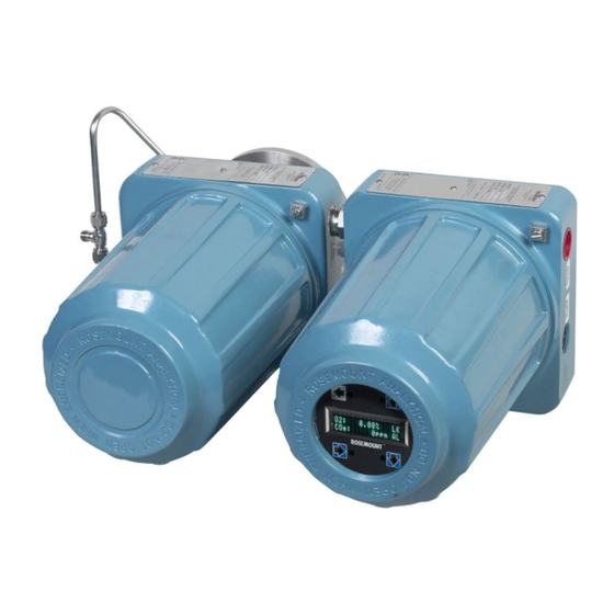
Description and specifications Description and specifications Component checklist A typical OCX 8800 Oxygen/Combustibles Transmitter package contains the items shown Figure 1-1. Reference Manual... - Page 12 OCX 8800. Check the model number against the transmitter features and options, making sure options specified by this number are on or included with the unit. Use this complete model number for any correspondence with Emerson. A list of accessories for use with the OCX 8800 is provided in Table 1-2.
-
Page 13: System Overview
This Instruction Manual supplies details needed to install, start up, operate, and maintain the OCX 8800. Signal conditioning electronics output a digital signal representing oxygen ) and combustibles (COe) values. This information, plus additional details, can be accessed with the 375 Field communicator or Emerson AMS software.. 1.2.2 System description The OCX 8800 is designed to measure oxygen and combustible concentrations in flue gas temperatures up to 1427 °C (2600 °F). -
Page 14: System Configurations
Description and specifications The transmitter measures net oxygen concentration in the presence of all the products of combustion, including water vapor. Therefore, it may be considered an analysis on a wet basis. In comparison with older methods, such as the portable apparatus, which provides an analysis on a dry gas basis, the wet analysis will, in general, indicate a lower percentage of oxygen. -
Page 15: System Features
Model 375 Field Communicator - The handheld field communicator requires Device Description (DD) software specific to the OCX 8800. The DD software is supplied with many Model 375 units, but can also be programmed into existing units at most Emerson service offices. Refer to Chapter 6Section additional information. -
Page 16: Handling The Ocx 8800
Description and specifications CPU can also initiate and perform calibrations. Three test gases and instrument air can be turned on and off by solenoids. Test gas flow to the sensors is regulated by a flow meter between the electronics and sensor housings. Instrument air is separated into eductor air, reference air, and dilution air. - Page 17 Description and specifications simplified installations for the OCX 8800.Figure 1-5 shows the dimensions for the optional sample tube support. Figure 1-6 shows the dimensions for the optional in-situ filters. Figure 1-7 shows the optional panel mounted blowback. A source of instrument air is required at the OCX 8800 for reference air, dilution air, and eductor air.
- Page 18 Description and specifications Figure 1-4: Typical System Installation - Integral Electronics Adapter plate Signal outputs (twisted pairs) Line voltage Instrument air supply (reference gas) High O test gas Low O test gas CO test gas OCX 8800...
- Page 19 Description and specifications Figure 1-5: Optional Sample Tube Support C. 0.75 (19) dia. on 7.5 (190) dia. B.C. 8 places D. 0.75 (19) dia. on 4.75 (121) dia. B.C. 4 places Reference Manual...
- Page 20 Description and specifications Probe length 18 in. 24.5 (621) 3 ft 42.5 (1078) 6 ft 78.5 (1993) 9 ft 114.5 (2907) Figure 1-6: Optional In-Situ Filters Figure 1-7: Optional Panel Mounted Blowback and Calibration/Reference Air Set (19 in. Rack or Wall Mount) OCX 8800...
-
Page 21: Specifications
Description and specifications Specifications Requires XPS transmitter, P/N 6A00358G03 Note All static performance characteristics are with operating variables constant. Specifications subject to change without notice. 1.3.1 Net O range 0-1% to 0-40% O , fully field selectable 1.3.2 Combustibles 0-1,000 ppm to 0-5%, fully field selectable 1.3.3 Accuracy Oxygen... -
Page 22: Nominal And Approximate Shipping Weights
Description and specifications Sensors housing -40 to 100 °C (-40 to 212 °F) Electronics housing -40 to 65 °C (-40 to 149 °F), ambient -40 to 85 °C (-40 to 185 °F), internal operating temperature of electronics inside housing, ® ™... -
Page 23: Calibration
Description and specifications 1.3.9 Calibration Semi-automatic or automatic 1.3.10 Calibration gas mixtures recommended (ref. test gas bottles kit #1A9919G04) 0.4% O , balance N 8% O , balance N 1000 ppm CO, balance air 1.3.11 Calibration gas flow 7 scfh (3.3 L/m), regulated to 20 to 30 psi (138 to 207 kPa) 1.3.12 Reference air 2 scfh (1 L/m), clean, dry, instrument-quality air (20.95% O... -
Page 24: Certifications
Description and specifications 1.3.16 Certifications Complies with the following standards: • 22.2 No. 94-M91; 22.2 No. 60529:05; ANSI/ISA S82.02.01; ANSI/ISA 12.00.01:2002; ANSI/ISA 12.22.01:2002;UL No. 50 (Ed 10); CAN/CSA C22.2 No. 61010-1-12; CAN/CSA C22.2 No. 60079-0:15; CAN/CSA C22.2 No. 60079-1:16; ISA 60079-0 (12.00.01) –... -
Page 25: Relative Humidity
Description and specifications 1.3.21 Relative humidity 5 to 95% (non-condensing) 1.3.22 Isolated output Oxygen 4-10 mAdc, 950 ohm maximum with HART or FOUNDATION Fieldbus capability only Combustibles 4-20 mAdc, 950 ohm maximum (not present with FOUNDATION Fieldbus) 1.3.23 Alarm Alarm output relay - dry contact, form C, 30 mA, 30 Vdc capability 1.3.24 Power consumption 750 W maximum... - Page 26 Description and specifications Table 1-1: Product matrix - OCX 8800 (continued) Code Probe mounting assembly (ANSI 2 in. 150 lb) 6 in. diameter flange. 4.75 in. BC with 4 x 0.75 in. diameter holes - standard O cell (DIN) 185 mm diameter flange, 145 mm BC with 4 x 18 mm diameter holes - standard O cell (DIN) 185 mm diameter flange, 145 mm BC with 4 x 18 mm...
- Page 27 Description and specifications Table 1-1: Product matrix - OCX 8800 (continued) Hastelloy Code Accessories None Cal. gas/flow rotometers & ref. gas set Cal. gas/flow rotometers & ref. gas set w/blowback Cal. gas/flow rotometers & ref. gas set w/blowback - panel mounted In-situ filter (stainless steel only) Example...
- Page 28 Description and specifications Table 1-2: Accessories (continued) Part number Description 6P00162H01 Flange insulator OCX 8800...
-
Page 29: Chapter 2 Install
Install Install WARNING! Before installing this equipment, read Section A.1. Failure to follow safety instructions could result in serious injury or death. WARNING! ELECTRICAL HAZARD Install all protective equipment covers and safety ground leads after installation. Failure to install covers and ground leads could result in serious injury or death. WARNING! HAZARDOUS AREAS The Xi Advanced Electronics can be installed in general purpose areas only. -
Page 30: Mechanical Installation
Install CAUTION! FLAMEPROOF DEVICES To maintain explosion-proof protection of the OCX88C in hazardous areas, all cable entry devices and blanking elements for unused apertures must be certified flameproof, suitable for the conditions of use, and properly installed. CAUTION! HIGH TEMPERATURE SURFACES To maintain explosion-proof protection of the OCX88C in hazardous areas, the sensor housing must not be mounted to any surface or flange that exceeds 195 °C (383 °F). -
Page 31: Installation
Install CAUTION! EQUIPMENT DAMAGE Do not allow the temperature of the electronics housing to exceed 185 °F (85 °C) or damage to the electronics may result. CAUTION! EQUIPMENT DAMAGE Whenever a positive stack pressure exists at the installation site, be sure to connect all pneumatic lines prior to installing the OCX 8800 in the stack or ductwork. - Page 32 I. Metal stack or duct wall J. Weld or bold adapter plate to metal wall. Joint must be air-tight. Note Dimensions are in inches with millimeters in parentheses. Only adapter plate is furnished by Emerson. Table 2-1: Adapter Plate Kit Mounting Dimensions Type part number...
- Page 33 Install Figure 2-2: Drip loops A. Duct wall Where a positive stack pressure exists at the installation site, connect all pneumatic lines prior to installing the OCX 8800 in the stack or ductwork. Reference Manual...
- Page 34 Install Note If process temperatures exceed 200 °C (392 °F), use anti-seize compound on stud threads to ease future removal of the OCX 8800. Insert sample and exhaust tubes through the opening in the mounting flange and bold the unit to the flange. CAUTION! EQUIPMENT DAMAGE Uninsulated stacks or ducts may cause ambient temperatures in the electronics housing...
- Page 35 Install Figure 2-3: Installation, OCX 8800 with Integral Electronics Insertion depth Removal envelope Table 2-2: 0.06 in. Thick Gasket ANSI 3535B18H02 3535B45H01 Table 2-3: Mounting Flange ANSI Flange dia. 6.00 (152) 7.28 (185) Hold dia. 0.75 (19) 0.71 (18) 4 holes equally spaced on B.C. 4.75 (121) 5.71 (145) dia.
-
Page 36: Electrical Installation
Install Insulate if exposed to adverse weather or extreme temperature changes. Install a protective housing and/or insulation around the unit. Electrical installation All wiring must conform to local and national codes. For reference, factory wired solenoid power connections are shown in Figure 2-4. - Page 37 Install Figure 2-4: Line Voltage, Earth, and 4 - 20 mA Connections Terminal block External tooth lockwasher Customer wiring Ground stud WARNING! ELECTRIC SHOCK Disconnect and lock out power before connecting the power supply. Failure to lock out power could result in serious injury or death. Reference Manual...
- Page 38 Install WARNING! ELECTRIC SHOCK Install all protective covers and safety ground leads after installation. Failure to install covers and ground leads could result in serious injury or death. WARNING! ELECTRIC SHOCK To meet the safety requirements of IEC 1010 (EC requirement) and ensure safe operation of this equipment, connection to the main electrical power supply must be made through a circuit breaker (min 10 A) which will disconnect all current-carrying conductors during a fault situation.
-
Page 39: Electrical Connections
Install 2.3.1 Electrical connections Electrical connections, power, and communications are made to the electronic enclosure. The connections are made through two 3/4 NPT ports in the enclosure using fittings and cables provided by you. Cable installation must meet NEC, IEC, and/or other applicable national or local codes for Class I, Zone 1, IIB +H2 T3/T6 permanently mounted equipment. -
Page 40: Remote Electronics Connections To Sensor Housing
Install 2.3.8 Remote electronics connections to sensor housing Make the following connections between the remote electronics and sensor housings with the electronics cable ordered with the package (Figure 2-5). Braided cable is available in lengths up to 150 ft (46 m). Figure 2-5: Electrical connections between remote electronics and sensor housing Note... - Page 41 Install Figure 2-6: Customer-furnished interconnect wiring or cables Heat shrink tubing, 2 ft long, 1/2 in. size 3/4 NPT hub size, liquid-tight strain relief connector Heat shrink tubing, 2 ft long, 1/2 in. size Ferrule, uninsulated 8 twisted pairs 24 AWG, stranded, insulated, tinned copper conductors, 200 °C (392 °F), 300 volts, with overall braid of 34 AWG tinned copper, 90% coverage and 24 AWG tinned copper, uninsulated drain wire See Note.
-
Page 42: Signal Connections
Install Heat shrink tubing 2 ft long, 1/2 in. size 3/4 NPT hub size, liquid-tight strain relief connectors Heat shrink tubing 2 ft long, 1/2 in. size Ferrule, uninsulated Stud size #6 Green, 16 AWG 8 conductors, 16 AWG, stranded, 200 °C (392 °F), 600 volts braided shield - tinned copper, 90% coverage with 18 AWG tinned copper, uninsulated, drain wire 4.25 ft long Teflon tubing 0.042 in. - Page 43 Install Figure 2-7: Pneumatic Installation, OCX with Reference Air Set (without Autocalibration) A. Flowmeter B. Combination filter - reg. C. 2 in. pressure gauge D. Flowmeter Table 2-4: Mounting Flange Flowmeter 1-10 scfh 771B635H01 Combination filter- 0-60 psig 1A994422H01 reg. 2 in.
-
Page 44: Reference Air Set And Solenoids Option Without Coe Zero Function
Install Install an air line between the instrument air outlet fitting on the electronics housing and the tee fitting on the sensor housing. CAUTION! FAULTY READINGS Do not use 100% nitrogen as an O low gas. It is suggested that O low gas be between 0.4% and 2.0% O . - Page 45 Install Figure 2-8: Pneumatic installation, OCX with Reference Air Set, Solenoids, and Autocalibration without COe Zero Function Flowmeter Flowmeter Combination filter - reg. 2 in. pressure gauge Table 2-5: Replacement Parts Flowmeter 1-10 scfh 771B635H01 Flowmeter 0.05 - 0.5 scfh 771B635H08 Combination filter-reg.
-
Page 46: Reference Air Set And Solenoids Option With Coe Zero Function
Install Table 2-5: Replacement Parts (continued) 2 in. pressure gauge 0-60 psig 275431-03 Procedure Install the reference air set according to the instructions in Section 2.4.1, steps 1 through 3. Refer to Figure 2-8. Connect the O low gas source to the CAL GAS LO O inlet fitting on the electronics housing. - Page 47 Install Figure 2-9: Pneumatic installation, OCX with reference air set, solenoids, and autocalibration with COe zero function Flowmeter Flowmeter Combination filter - reg 2 in. pressure gauge Table 2-6: Replacement Parts Flowmeter 0.05 - 0.5 scfh 7718635H08 Reference Manual...
-
Page 48: Reference Air Set, Solenoids, And Blowback Option With Coe Zero Function
Install Table 2-6: Replacement Parts (continued) Flowmeter 1-10 scfh 7718635H01 Combination filter - reg 0-60 psig 1A99422H01 2 in. pressure gauge 0-60 psig 275431-03 Note If instrument is to be used as the high O calibration gas, the low O and COe calibration gases must also be set to the same pressure (e.g., 45 psig) 2.4.4... - Page 49 Install Figure 2-10: Pneumatic installation, OCX with reference air set, solenoids, blowback, and autocalibration without COe zero function Flowmeter Check valve Flowmeter Combination filter-reg Combination filter-reg 2 in. pressure gauge Blowback valve, air operated Pneumatic actuator Table 2-7: Replacement Parts Flowmeter 1-10 scfh 771B635H01...
- Page 50 Pressure regulator with 1/8 in. inlet port is factory set for 45 psig. Regulator with 1/4 in. inlet port is factory set for 55 psig. If regulators are not installed in correct locations, the Rosemount OCX 8800 will not work.
- Page 51 Install Figure 2-11: Pneumatic Installation, OCX with Reference Air Set, Solenoid, Blowback, and Autocalibration with CO3 Zero Function Flowmeter Check valve Flowmeter Pneumatic actuator 2 in. pressure gauge Combination filter-reg Combination filter-reg Table 2-8: Replacement Parts Flowmeter 1-10 scfh 771B635H01 Check valve 5 psig 7309A62H01...
-
Page 52: Initial Startup
Install Table 2-8: Replacement Parts (continued) Combination filter/reg 0-60 psig 4505C21G11 Combination filter/reg 0-60 psig 1A99422H01 Note During blowback option, states of both solenoid valves change. Note Wall mount the air-operated blowback valve on a suitable mounting plate. Note Actuating air pressure at blowback valve inlet port must be at least 51 psig to fully actuate the valve. Note If instrument is to be used as the high O2 calibration gas, the low O2 and COe calibration must also be set to the same pressure (i.e., 55 psig). -
Page 53: Configuration And Startup
3.1.1 Verify configuration - HART electronics There are three switches on the microprocessor board which are user configurable for the Rosemount OCX 8800 with HART electronics (Figure 3-1). SW1 determines if the O 4-20 mA signal is internally or externally powered. SW2 determines if the COe 4-20 mA signal is internally or externally powered. - Page 54 Configuration and startup Figure 3-1: Rosemount OCX 8800 Defaults - HART Electronics Switch default positions shown. 21.1 mA/3.5 mA: O 4-20 mA signal Rail limits: Open High - 21.1 mA Closed Low - 3.5 mA COe 21.1 mA/3.5 mA: COe 4-20 mA signal Rail limits: Open High - 21.1 mA...
-
Page 55: Verify Configuration - Fieldbus Electronics
Configuration and startup • Position 1 determines the O 4-20 mA signal rail limit. The settings are high, 21.1 mA, or low, 3.5 mA. The factory setting is low, 3.5 mA. • Position 2 determines the COe 4-20 mA signal rail limit. The settings are high, 21.1 mA, or low, 3.5 mA. -
Page 56: Initial Power Up
Configuration and startup Verify that the following switch settings are correct for your transmitter installation: SW3: The factory sets this switch as follows: • Position 1 not used. • Position 2 not used. Positions 3 and 4 must be set up as shown for proper software control of the device heaters. -
Page 57: Setting Test Gas Values With The Loi
Configuration and startup Use the 375 Field Communicator to access the Fieldbus menu. From the TRANSDUCER menu, select O2 CAL. From O2 CAL, select O2 CAL SETUP. From O2 CAL SETUP, select O2 HIGH GAS. Enter the percent O used for the high test gas. -
Page 58: Configuring The Calibration Solenoids With The Field Communicator - Fieldbus
Configuration and startup From the O2 CAL PARAMS/COe CAL PARAMS menu, select Solenoids. Select Yes to enable the solenoids. 3.4.2 Configuring the calibration solenoids with the Field Communicator - Fieldbus Complete the following steps to configure the calibration solenoids with the Field Communicator using the Foundation Fieldbus communication protocol. -
Page 59: Configuring Blowback With The Field Communicator - Fieldbus
Configuration and startup From the INPUT/OUTPUT menu, select BLOWBACK. From the BLOWBACK menu, select BlBk Enabled. Select Yes to enable blowback. Also set the following parameters: • BlBk Intrvl: Length of time between blowback events (60 minutes recommended). • BlBk Period: Length of time blowback is activated (5 seconds recommended). •... -
Page 60: Calibration Verify Feature
Configuration and startup • Force Blow Bk: Initiates a blow back event manually. Calibration verify feature The calibration verify feature flows one or more calibration gases to verify the analyzer is reading correctly. The calibration verify feature flows each calibration gas on demand to verify calibration, but does not change the slope or constant of the current calibration. -
Page 61: Performing A Calibration Verify With The Field Communicator - Fieldbus
Configuration and startup 3.6.2 Performing a calibration verify with the Field Communicator - Fieldbus Complete the following steps to perform a calibration verify with the Field Communicator using the Foundation Fieldbus communication protocol. Use the 375 Communicator or AMS software to access the Fieldbus menu. From the TRANSDUCER block menu, select METHODS. -
Page 62: Calibration Tolerance Feature
Configuration and startup Calibration tolerance feature The calibration tolerance feature provides a mechanism to fail a calibration if the calibration measurement does not fall within a specific tolerance of the test gas value. The tolerance is preset within the transmitter software and is not user-adjustable. The tolerance is different between the oxygen and combustibles test gases. -
Page 63: Configuring The Calibration Tolerance Feature With The Loi
Configuration and startup 3.7.3 Configuring the calibration tolerance feature with the Complete the following steps to configure the calibration tolerance feature with the LOI. Use the Z pattern to enter the LOI menu tree. From the SYSTEM menu, select Calib Setup. From the Calib Setup menu, select the following: •... -
Page 64: Configuring The Coe Zero Feature With The Field Communicator - Hart
Configuration and startup WARNING! During the COe zero function, the analog output signals may track the oxygen and combutibles readings if configured to do so. To avoid a potentially dangerous operating condition, the transmitter must be removed from the automatic combustion control loop before performing the COe zero function. -
Page 65: Configuring The Coe Zero Feature With The Loi
Configuration and startup • COe Zero Enable: Select Yes or No to enable or disable this feature. • COe Zero Interval: Length of time between COe zero events. Range is 60 to 480 minutes. Default is 60 minutes. • COe Zero Duration: Length of time the COe zero gas flows. Range is 120 to 600 seconds. -
Page 66: Reset With The Loi
Configuration and startup 3.9.1 Reset with the LOI Complete the following steps to reset the transmitter with the LOI. Use the Z pattern to enter the LOI menu tree. Select the SYSTEM submenu. From the SYSTEM submenu, select the Status submenu. From the Status submenu, select Reset Device. -
Page 67: Using The Loi
Using the LOI Using the LOI This chapter describes the installation and operation of the LOI module in the OCX 8800. Display orientation The LOI module mounts to a connector on the LOI board. The board is installed on the end of the electronics stack in the electronics housing, Figure 4-1. -
Page 68: Loi Controls
Using the LOI LOI controls 4.2.1 Overview The LOI, shown in Figure 4-2, uses a bright blue gas-fluorescent display. Intensity is adjustable. There is an infrared LED source and a detector for each key. The detectors can detect a finger placed above the button through the glass window. There is no need to open the instrument in bad weather or in hazardous areas in order to access the electronics. -
Page 69: Loi Key Functions
Using the LOI Figure 4-2: LOI assembly Touch confirmation LED Selection arrow Lockout notation Status code Selection arrows Display window Selection arrow (Enter key) 4.2.2 LOI key functions The gray (top left) key moves one level higher in the menu structure. When entering parameter values (numbers), this key moves the cursor to the left. -
Page 70: Lockout
Using the LOI The up and down pointing keys are used to increment up and down when selecting from a vertical list of menu items. These keys are also used for incrementing values up and down for new data input. 4.2.3 Lockout The LOI has a lockout feature that prevents nuisance actuation by someone brushing... - Page 71 Using the LOI Figure 4-3: Z pattern entry Reference Manual...
-
Page 72: Loi Status Codes
Using the LOI 4.2.4 LOI status codes The LOI display shows a status code in the lower right hand corner of the display. There are nine status codes to indicate the existing status of the device during operation. The status code descriptions are shown in Table 4-1. - Page 73 Using the LOI Figure 4-4: LOI menu tree Reference Manual...
- Page 74 Using the LOI OCX 8800...
- Page 75 Using the LOI Reference Manual...
-
Page 76: First Column Submenus
Using the LOI 4.3.1 First column submenus From the operating display (O2 % and COe ppm), the left-pointing Enter key is the only option to move into the first column submenus of the LOI menu tree. The first column contains three submenus: SENSOR DATA, CALIBRATION, and SYSTEM. From the operating display, SENSOR DATA is displayed when the right-pointing key is selected. -
Page 77: Third And Fourth Column Submenus
Using the LOI 4.3.3 Third and fourth column submenus From the second column submenus, selecting the right key moves the display into the third column submenus. The third column submenu may be another menu or a list of parameters. The up and down keys allow the display to move to the different parameters or menus. - Page 78 Using the LOI OCX 8800...
-
Page 79: Chapter 5 Calibration
Calibration Calibration Overview During calibration, two calibration gases with known O concentrations and one calibration gas with a known COe concentration are applied to the transmitter. Slope and constant values are calculated to determine if the transmitter is correctly measuring net concentration of O and combustibles in the industrial process. -
Page 80: Operator-Initiated Autocalibration
Calibration If you want, the O2NxtCalTm and the COENxtCalTm (next calibration time) parameters can be changed to synchronize a calibration at a specific day or time. CAUTION! When setting automatic calibration times, set CallIntrvl and NxtCalTm so that O and COe are not calibrated simultaneously. -
Page 81: Manual Calibration Using The Optional Loi
Calibration 5.4.1 Manual calibration using the optional LOI Use the following procedure to perform a manual calibration with the LOI. If necessary, refer to the menu tree in Chapter 4. Once the manual calibration is intiated at the LOI, a series of prompts appear giving instructions to the operator. Procedure Use the Right key to select the CALIBRATION first column submenu. -
Page 82: Manual O Calibration Using The Field Communicator - Hart
Calibration 5.4.2 Manual O calibration using the Field Communicator - HART To perform a manual O calibration using the HART Communicator or AMS, use the following procedure. If necessary, refer to Section 6.3 for the HART menu tree. Note To select a menu item, either use the Up and Down keys to scroll to the menu item and press the Right key or use the number keypad to select the menu item number. -
Page 83: Manual Coe Calibration Using The Field Communicator - Hart
Calibration Select Start/Next Cal Step to start applying the O low gas. The time to apply the test gas is specified by the Gas Time. The Calibration Status is automatically changed to FlowO2Low and then ReadO2Low for a period of time. During this period, if you try to go the next calibration step by pressing OK and selecting Start/Next Cal Step, you are prompted with Operator step command is not accepted at this time. - Page 84 Calibration Select CAL CONTROL from the CALIBRATION menu. Select CAL METHODS from the CAL CONTROLPERFORM CAL menu. From the CAL METHODS menu, select the type of calibration desired: COe Calibration. In the first Calibration screen, a Loop should be removed from automatic control warning appears.
-
Page 85: Manual O And Coe Calibration Using The Field Communicator - Fieldbus
Calibration The Calibration Status is automatically changed to FlowCOeHi and then ReadCOeHi for a period of time. During this period, if you try to go the next calibration step by pressing OK and selecting START CAL/STEP CAL, you are prompted with Operator step command is not accepted at this time. - Page 86 Calibration The Select Action screen is static, and data is not automatically refreshed. • Calibration Step = Idle • Step Time Remaining = 0 seconds • O2 Value = 0.40% Combustibles Value = 1000 ppm • a. Update Display b. Next Calibration Step c.
-
Page 87: D/A Trim Procedures - Loi
Calibration The calibration step changes to Read Comb Low Gas for a period of time. When ready, the Calibration step stops at Apply Comb High Gas. Switch off the O high gas and switch on the COe test gas. Verify the COe concentration measured matches the COe test gas parameter in the setup. -
Page 88: Coe D/A Trim Procedure Using The Loi
Calibration Refer to Figure 2-2. Connect a digital multimeter to read the milliamp output from the O D/A converter circuit. Connect the positive lead to the AOUT1+ terminal and connect the negative lead to the AOUT1- terminal. Then touch Enter on the LOI. The LOI displays 4 mA...Meter. -
Page 89: D/A Trim Procedures - Hart
Calibration Note If you wish to exit D/A trim with no changes, step through the procedure using yes responses and enter no meter readings. Remove the electronics housing cover. Refer to Figure 2-2. Connect a digital multimeter to read the milliamp output from the COe D/A converter circuit. - Page 90 Calibration Procedure Prom the DIAG/SERVICE menu, select D/A TRIM. Select O2 D/A TRIM. Press Right to start the procedure. If you wish to exit D/A Trim with no changes, select ABORT. The Field Communicator displays WARNING: Loop should be removed from automatic control.
-
Page 91: Coe D/A Trim Procedure Using Hart
Calibration Using Up or Down, select 1 Yes or 2 No. Press ENTER. If No, the process repeats from step 5. The Field Communicator displays NOTE: Loop may be returned to automatic control. 5.6.2 COe D/A trim procedure using HART Use the following procedure to perform the COe D/A trim procedure using the Field Communicator. - Page 92 Calibration Press OK. Read the COe milliamp output at the digital multimeter. Enter the reading at the Field Communicator and press ENTER. Select ABORT to exit without changes. The Field Communicator displays Setting Fld dev output to 4 mA. Press OK. The Field Communicator displays Fld dev output 4.00 mA equal to reference meter? Using Up or Down, select 1 Yes or 2 No.
-
Page 93: Chapter 6 Field Communicator
Field Communicator Field Communicator Overview The 375 Field Communicator is a communication interface device. It supports HART and Fieldbus devices, letting you configure and troubleshoot in the field. The 375 Field Communicator includes an LCD with touch-screen display and keypad. Use the touch-screen or keypad to enter data into the 375 Field Communicator. -
Page 94: Connecting To A Fieldbus Segment
Field Communicator Figure 6-1: 375 Communicator connections - HART Loop connectors Field Communicator Model 375 Lead set 6.2.2 Connecting to a Fieldbus segment Connect the 375 Field Communicator with the supplied lead set in parallel with the device to a Fieldbus segment, Figure 6-2. - Page 95 Field Communicator WARNING! EXPLOSION Do not make connections to the Field Communicator's serial port, digital signal line, or NiCad recharger jack in an explosive atmosphere. Expolsions can result in death or serious injury. Figure 6-2: 375 Communicator connections - Fieldbus Terminal connectors Terminal block Terminals...
-
Page 96: Hart Menu Tree
Field Communicator HART menu tree This section provides a menu tree for the Field Communicator. This menu is specific to OCX 8800 applications. OCX 8800... - Page 97 Field Communicator Figure 6-3: HART menu tree Reference Manual...
- Page 98 Field Communicator OCX 8800...
- Page 99 Field Communicator Reference Manual...
-
Page 100: Fieldbus Menu Tree
Field Communicator Fieldbus menu tree This section consists of a menu for the Field Communicator using the Fieldbus protocol. This menu is specific to the Hazardous Area OCX 8800 applications. Refer to the Fieldbus parameter descriptions for the applicable range, units, and description for the Fieldbus menu parameters. - Page 101 Field Communicator Figure 6-4: Fieldbus menu tree Reference Manual...
- Page 102 Field Communicator OCX 8800...
- Page 103 Field Communicator Reference Manual...
- Page 104 Field Communicator OCX 8800...
-
Page 105: Chapter 7 Foundation Fieldbus
Fieldbus an enabling technology. Emerson offers a full range of products from field devices to the DeltaV scalable control system to allow an easy transition to Fieldbus technology. The Fieldbus retains the features of the 4-20 mA analog system, including standardized... -
Page 106: Function Blocks
Foundation Fieldbus 7.1.3 Function blocks Function blocks within the Fieldbus device perform the various functions required for process control. Because each system is different, the mix and configuration of functions are different. Therefore, the Fieldbus Foundation has designed a range of function blocks, each addressing a different need. -
Page 107: Device Descriptions
Foundation Fieldbus Once the inputs are snapped, the alorithm operates on them, generating outputs as it progresses. Algorithm executions are controlled through the setting of contained parameters. Contained parameters are external to function blocks and do not appear as normal input and output parameters. However, they may be accessed and modified remotely, as specified by the function block. -
Page 108: Network Communication
Foundation Fieldbus Resource blocks Resource blocks contain the hardware specific characteristics associated with a device; they have no input or output parameters. The algorithm within a resource block monitors and controls the general operation of the physical device hardware. The execution of this algorithm is dependent on the characteristics of the physical device, as defined by the manufacturer. -
Page 109: Link Active Scheduler (Las)
Addresses 0 through 15 are reserved for group addressing and for use by the data link layer. For all Emerson Fieldbus devices, addresses 20 through 35 are available to the device. If there are two or more devices with the same address, the first device to start uses its programmed address. -
Page 110: Ocx Function Blocks
Foundation Fieldbus OCX function blocks 7.3.1 Implemented function blocks Table 7-1 shows the OCX implemented function blocks. Table 7-1: OCX implemented function blocks Function block Description Resource block Transducer block Analog input block 1 (AI1) See TB Channel Assignment, Table 7-19 Analog input block 2 (AI2) See TB Channel Assignment, Table 7-19... -
Page 111: Mapping Of Pwa
Foundation Fieldbus Table 7-2: Hazardous Area OCX 8800 PWA (continued) PlantWeb Alert Severity level default Calibration Recommended Advisory NV Memory Failure Failed NV Writes Deferred Advisory High Electronics Temperature Maintenance ADC Failure Failed Line Input Out of Range Advisory Inter Board Comm Failure Failed Simulate Active Advisory... - Page 112 Foundation Fieldbus Table 7-3: Descriptions of PlantWeb Alerts What does the Recommended Alerts Alarms AMS tab alert indicate? action Description Sensor Malfunc- Transducer block: Sensor Alerts This alert is active Check sensor 1. The oxygen tion 1. O Cell Open when the sensor wires for loose or cell interface...
- Page 113 Foundation Fieldbus Table 7-3: Descriptions of PlantWeb Alerts (continued) What does the Recommended Alerts Alarms AMS tab alert indicate? action Description also cause this alarm. Refer Section 8.2 for details. Sensor Degraded Transducer block: Sensor Alerts This alert is active Replace the oxy- Oxygen cells de- Cell Impe-...
- Page 114 Foundation Fieldbus Table 7-3: Descriptions of PlantWeb Alerts (continued) What does the Recommended Alerts Alarms AMS tab alert indicate? action Description Thermocouple Transducer block: T/C Heater Alerts This alert indi- Check the ther- When the heater Malfunction 1. O T/C Open cates a miswired mocouple wires thermocouple...
- Page 115 Foundation Fieldbus Table 7-3: Descriptions of PlantWeb Alerts (continued) What does the Recommended Alerts Alarms AMS tab alert indicate? action Description Sensor Heater Transducer block: T/C Heater Alerts This alert indi- Check heater cir- Mechanical or Malfunction 1. O Heater Fail- cates that no cuit for loose or thermal stress...
- Page 116 Foundation Fieldbus Table 7-3: Descriptions of PlantWeb Alerts (continued) What does the Recommended Alerts Alarms AMS tab alert indicate? action Description Sensor Heater Transducer block: T/C Heater Alerts This alert indi- Check heater wir- A heater over- Over Tempera- 1. O Cell Temp.
- Page 117 Foundation Fieldbus Table 7-3: Descriptions of PlantWeb Alerts (continued) What does the Recommended Alerts Alarms AMS tab alert indicate? action Description Calibration Rec- Transducer block: Calibration Alerts This alert indi- Check instrument Oxygen cells de- ommended Calibration Rec- cates that the accuracy and/or grade over time ommended...
- Page 118 Foundation Fieldbus Table 7-3: Descriptions of PlantWeb Alerts (continued) What does the Recommended Alerts Alarms AMS tab alert indicate? action Description NV Memory Fail- Transducer block: FF/ Device Alerts The non-volatile At startup, wait 2 This alarm gener- EEPROM Corrupt parameter stor- minutes with ally occurs during...
- Page 119 Foundation Fieldbus Table 7-3: Descriptions of PlantWeb Alerts (continued) What does the Recommended Alerts Alarms AMS tab alert indicate? action Description NV Writes Defer- Resource block: FF/Device Alerts A high number of 1. NV Writes De- writes has been ferred detected to non- volatile memory.
-
Page 120: Pwa Simulate
Foundation Fieldbus Table 7-3: Descriptions of PlantWeb Alerts (continued) What does the Recommended Alerts Alarms AMS tab alert indicate? action Description Line Input Out of Transducer block: Device Alerts This alert indi- Check line input The device power Range 1. Line Frequen- cates that the line power for proper supply continu-... -
Page 121: Fieldbus/Pwa Simulate
Foundation Fieldbus Allowing simulating means that these parameters get write permission, and the host's written value is the only one which is used for the parameter's read back value. The data which comes from the transmitter is not used in this case. 7.4.4 Fieldbus/PWA simulate Fieldbus simulation and PWA simulation can be enabled and disabled using the DD... -
Page 122: Configure Simulation With The Model 375 Field Communicator
Foundation Fieldbus Figure 7-3: Simulate PWA screen Now select Simulation on or Simulation off from the Simulate PWA screen. When Fieldbus simulation is on, the Simulation Switch LED is illuminated. When PWA simulation is off, the PWA Simulate LED is illuminated. If PWA simulation is on, all PWA active parameters and resource and transducer block status parameters are configurable. -
Page 123: Support Resource Block Errors
Foundation Fieldbus Select Enable to enable PWA simulation or Disable to disable the simulation feature. Once the method is complete, select Resource | Simulate PWA in the resource block. If the simulation is enabled, the PWA Simulate parameter is configurable. Otherwise it is read-only. -
Page 124: Transducer Block Parameters
Foundation Fieldbus 7.6.1 Transducer block parameters Table gives a description of all parameters or gives the location of the Fieldbus specifications where the description can be found. Table 7-4: Transducer block parameter description Parameter mnemonic Valid range Units Description ALARM_RELAY_EVENT1 Table 7-8. - Page 125 Foundation Fieldbus Table 7-4: Transducer block parameter description (continued) Parameter mnemonic Valid range Units Description CAL_GAS_TIME 60 - 1200 Seconds The amount of time cali- bration gas should flow be- fore a reading is taken. CAL_PURGE_TIME 60 - 1200 Seconds The amount of time before returning the output to process after calibrating.
- Page 126 Foundation Fieldbus Table 7-4: Transducer block parameter description (continued) Parameter mnemonic Valid range Units Description COMB_HTR_DUTYCYCLE Combustibles heater duty cycle. COMB_PERCENT_OF_RANGE The percent of range of the current combustibles read- ing. COMB_PREVIOUS_CONSTANT The combustibles calibra- tion constant from the pre- vious good calibration.
- Page 127 Foundation Fieldbus Table 7-4: Transducer block parameter description (continued) Parameter mnemonic Valid range Units Description COMB_SLOPE 200-450 PPM/Ohm The combustibles calibra- tion slope. COMB_SLOPE_WARNING 25.0 - 99.0 % of FS The combustibles slope warning threshold. COMB_T90 0 - 300 Seconds The amount of time that the combustibles process variable will take to reach...
- Page 128 Foundation Fieldbus Table 7-4: Transducer block parameter description (continued) Parameter mnemonic Valid range Units Description COZERO_UPDATE 0: Off - 1: On Enumerated Indicates whether the com- bustibles calibration con- stants should be updated after combustibles sensor zero. DETAILED_STATUS_1 0 - 16777215 Bit Enum A bit-enumerated value used to communicate the...
- Page 129 Foundation Fieldbus Table 7-4: Transducer block parameter description (continued) Parameter mnemonic Valid range Units Description O2_CAL_POINT_LO 0-40 The value of the low O test gas. O2_CELL_IMPEDANCE Ohms The instantaneous impe- dance value for the O cell. O2_CONSTANT -20.0 to 20.0 The O calibration con- stant.
- Page 130 Foundation Fieldbus Table 7-4: Transducer block parameter description (continued) Parameter mnemonic Valid range Units Description O2_SENSOR_INPUT The raw value of the O sensor input. O2_SENSOR_TYPE See FF-903, Section 3.3 and Section 4.3. O2_SETPOINT ° C heater temperature set point. O2_SLOPE 34.5-47.5 mV/Decade The O...
- Page 131 Foundation Fieldbus Table 7-4: Transducer block parameter description (continued) Parameter mnemonic Valid range Units Description SENSOR_HOUSING_TEMP_IN- Sensor housing CJC voltage (valid only with Type 3 sen- sor). SENSOR_HOUSING_TEMP_ ° C The highest sensor housing temperature read since power on. SENSOR_HOUSING_TYPE 0, 1, 2, 3 Enumerated This is the sensor housing...
-
Page 132: Transducer Block Enumerations
Foundation Fieldbus Table 7-4: Transducer block parameter description (continued) Parameter mnemonic Valid range Units Description VERIFY_STATE_TIME Seconds Time remaining for the cur- rent calibration check state. XD_ERROR See FF-903, Section 3.3. Transducer block enumerations 7.7.1 Calibration states During a running calibration procedure, the states below reflect the current step that the calibration is running in. -
Page 133: Calibration Step Command
Foundation Fieldbus Table 7-5: Calibration state - values Index CAL_STATE description Operator ack required to continue Idle Yes, cal can also be initiated from in- ternally generated events. Apply O low gas Yes, if parameter Solenoids Present is Flow O low gas Read O low gas... - Page 134 Foundation Fieldbus Starting a calibration procedure of a sensor is only allowed if there is no procedure already running on the same sensor. If we do not want to wait to finish the already running procedure, we first have to cancel it before starting the new procedure. Table 7-7: Blowback state enumerations BLOWBACK_STATE description...
- Page 135 Foundation Fieldbus Table 7-9: Operating mode enumerations (continued) Operating mode description ALARM SYS FAULT CAL RECOMMENDED Table 7-10: Sensor housing enumerations SENSOR_HOUSING_TYPE description TYPE 1 TYPE 2 TYPE 3 Table 7-11: Cal results bit enumerations CAL_RESULTS description slope error constant error tolerance check failed CO slope error constant error...
- Page 136 Foundation Fieldbus Table 7-13: Calibration verify step values VERIFY_STATE_STEP description Start flow high O Start flow low O Start flow high COe gas Purge gas No effect Table 7-14: COe zero state enumerations COZERO_STATE description Idle Flowing Purging Table 7-15: COe out tracks enumerations COZERO_OUTTRAK description None...
- Page 137 Foundation Fieldbus Table 7-16: Detailed status (continued) Value of XD_ERROr (see Alarm number Description FF-903) Combustibles thermocouple Mechanical failure open Combustibles thermocouple Mechanical failure shorted Combustibles thermocouple Mechanical failure reversed Combustibles temperature low Mechanical failure Combustibles temperature Mechanical failure high Combustibles temperature Mechanical failure very high...
-
Page 138: Transducer Block Channel Assignments For Ai Blocks
Foundation Fieldbus Table 7-16: Detailed status (continued) Value of XD_ERROr (see Alarm number Description FF-903) Inter-board communication Electronics failure failure Reserved for FB 7.7.3 Transducer block channel assignments for AI blocks The following table lists the OCX transducer block I/O channels for the AI block. Table 7-17: I/O channel assignments Transducer block channel val-... -
Page 139: Transducer Block Simulate
Foundation Fieldbus • Occurrence: Normal • Quality value: GOOD • Quality substatus value: NON_SPECIFIC • Limit value: NOT_LIMITED Table 7-19: I/O channel status Quality substatus Channel Occurrence Quality value value Limit value Powerup, Warmup, NON_SPECIFIC NOT_LIMITED Stabilize Normal GOOD NON_SPECIFIC NOT_LIMITED Calibrating, Cal verify, UNCERTAIN... -
Page 140: Analog Input (Ai) Function Block
Foundation Fieldbus • Other error: Set whenever XD_ERROR is non-zero. Analog input (AI) function block 7.8.1 Introduction The transmitter has four transducer block input/output channels (Table 7-23) for the AI function blocks. The status of channel values are defined in Table 7-25. - Page 141 Foundation Fieldbus manually. The Manual mode is reflected on the output status. A discrete output (OUT_D) is provided to indicate whether a selected alarm condition is active. Alarm detection is based on the OUT value and user specified alarm limits. Table 7-20 lists the AI block parameters and their units of measure, descriptions, and index numbers.
- Page 142 Foundation Fieldbus Table 7-20: Definitions of analog input function block system parameters (continued) Parameter Index number Units Description BLOCK_ALM None The block alarm is used for all configuration, hardware, connection failure, or sys- tem problems in the block. The cause of the alert is en- tered in the Subcode field.
- Page 143 Foundation Fieldbus Table 7-20: Definitions of analog input function block system parameters (continued) Parameter Index number Units Description HI_ALM None The HI alarm data, which in- cludes a value of the alarm, a timestamp of occurrence, and the state of the alarm. HI_HI_ALM None The HI HI alarm data, which...
- Page 144 Foundation Fieldbus Table 7-20: Definitions of analog input function block system parameters (continued) Parameter Index number Units Description LO_LO_LIM EU of PV_SCALE The setting for the alarm limit used to detect the LO LO alarm condition. LO_LO_PRI None The priority of the LO LO alarm.
-
Page 145: Simulation
Foundation Fieldbus Table 7-20: Definitions of analog input function block system parameters (continued) Parameter Index number Units Description STRATEGY None The strategy field can be used to identify grouping of blocks. This data is not checked or processed by the block. - Page 146 Foundation Fieldbus With simulation enabled, the actual measurement value has no impact on the OUT value or the status. OCX 8800...
- Page 147 Foundation Fieldbus Figure 7-5: Analog input function block schematic Alarm_type Status_opts Mode Mode PV_Ftime IO_opts Field_val Out_scale XD_scale Channel Low_cut Alarm_hys Hi_Hi_Lim Hi_Lim Lo_Lo_Lim Lo_Lim Note OUT = Block output value and status. OUT_D = Discrete output that signals a selected alarm condition. Reference Manual...
-
Page 148: Filtering
Foundation Fieldbus Figure 7-6: Analog input function block timing diagram 7.8.3 Filtering The filtering feature changes the response time of the device to smooth variations in input readings caused by rapid changes in input. You can adjust the filter time constant (in seconds) using the PV_FTIME parameter. -
Page 149: Indirect Signal Conversion
Foundation Fieldbus 7.8.6 Indirect signal conversion Indirect signal conversion converts the signal linearly to the accessed channel input value (or the simulated value when simulation is enabled) from its specified range (XD_SCALE) to the range and units of the PV and OUT parameters (OUT_SCALE). 7.8.7 Indirect square root Indirect square root signal conversion takes the square root of the value computed with... -
Page 150: Modes
Foundation Fieldbus Table 7-21: BLOCK_ERR conditions (continued) Condition num- Condition name and description Device fault state set Device needs maintenance soon Input failure/process variable has bad status: The hardware is bad, or a bad sta- tus is being simulated. Output failure: The output is bad based primarily upon a bad input. Memory failure Lost static data Lost NV data... -
Page 151: Status Handling
Foundation Fieldbus In order to avoid alarm chattering when the variable is oscillating around the alarm limit, an alarm hysteresis in percent of the PV span can be set using the ALARM_HYS parameter. The priority of each alarm is set in the following parameters: •... -
Page 152: Advanced Features
Foundation Fieldbus Note The AI block only supports the BAD if Limited option. Unsupported options are not grayed out; they appear on the screen in the same manner as supported options. 7.8.12 Advanced features The AI function block provided with the Fisher-Rosemount Fieldbus devices provides added capability through the addition of the following parameters. -
Page 153: Application Examples
Foundation Fieldbus 7.8.14 Application examples Temperature transmitter - situation A temperature transmitter with a range of -200 to 450 °C (-328 to 842 °F). Temperature transmitter - solution Table lists the appropriate configuration settings, and Figure illustrates the correct function block configuration. Table 7-22: Analog input function block configuration for a typical temperature transmitter... - Page 154 Foundation Fieldbus Figure 7-8: Situation #1 diagram Solution to situation #1 Table 7-23 lists the appropriate configuration settings, and Figure 7-9 illustrates the correct function block configuration. Table 7-23: Analog input function diagram for a pressure transmitter used in level measurement (situation #1) Parameter Configured values...
- Page 155 Foundation Fieldbus Figure 7-9: Function block diagram for a pressure transmitter used in level measurement Situation #2 The transmitter in situation #1 is installed below the tank in a position where the liquid column in the impulse line, when the tank is empty, is equivalent to 2.0 psi (Figure 7-10).
- Page 156 Foundation Fieldbus Figure 7-10: Situation #2 diagram Table 7-24 lists the appropriate configuration settings. Table 7-24: Analog input function diagram for a pressure transmitter used in level measurement (situation #2) Parameter Configured values L_TYPE Indirect XD_SCALE 2 to 9 psi OUT_SCALE 0 to 16 ft OCX 8800...
-
Page 157: Differential Pressure Transmitter To Measure Flow
Foundation Fieldbus 7.8.16 Differential pressure transmitter to measure flow Situation The liquid flow in a line is to be measured using the differential pressure across an orifice plate in the line, and the flow measurement will be used in a flow control loop. Based on the orifice specification sheet, the differential pressure transmitter was calibrated for 0 to 20 in H 0 for a flow of 0 to 800 gal/min, and the transducer was not configured to take the... - Page 158 Foundation Fieldbus Table 7-26: Troubleshooting (continued) Symptom Possible cause Corrective action 2. Configuration error 2. BLOCK_ERR shows the configura- tion error bit set. The following are pa- rameters that must be set before the block is allowed out of OOS. a.
-
Page 159: Proportional/Integral/Derivative (Pid) Function Block
Foundation Fieldbus Proportional/integral/derivative (PID) function block The PID function block combines all of the necessary logic to perform proportional/ integral/derivative (PID) control. The block supports mode control, signal scaling and limiting, feedforward control, override tracking, alarm limit detection, and signal status propagation. - Page 160 Foundation Fieldbus Figure 7-13: PID equation: Standard and Series To further customize the block use for your application, you can configure filtering, feedforward inputs, tracking inputs, setpoint and output limiting, PID equation structures, and block output action. Table 7-27 lists the PID block parameters and their descriptions, units of measure, and index numbers, and Figure 7-14 illustrates the internal components...
- Page 161 Foundation Fieldbus Table 7-27: PID function block system parameters (continued) Parameter Index number Units Descriptions ALERT_KEY None The identification number of the plant unit. This infor- mation may be used in the host for sorting alarms, etc. ALG_TYPE None Selects filtering algorithm as backward or bilinear.
- Page 162 Foundation Fieldbus Table 7-27: PID function block system parameters (continued) Parameter Index number Units Descriptions BLOCK_ALM None The block alarm is used for all configuration, hardware, connection failure, or sys- tem problems in the block. The cause of the alert is en- tered in the Subcode field.
- Page 163 Foundation Fieldbus Table 7-27: PID function block system parameters (continued) Parameter Index number Units Descriptions DV_HI_PRI None The priority of the deviation high alarm. DV_LO_ALM None The DV LO alarm data, which includes a value of the alarm, a timestamp of occurrence, and the state of the alarm.
- Page 164 Foundation Fieldbus Table 7-27: PID function block system parameters (continued) Parameter Index number Units Descriptions HI_HI_ALM None The HI_HI alarm data, which includes a value of the alarm, a timestamp of oc- currence, and the state of the alarm. HI_HI_LIM EU of PV_SCALE The setting for the alarm limit used to detect the HI...
- Page 165 Foundation Fieldbus Table 7-27: PID function block system parameters (continued) Parameter Index number Units Descriptions MODE_BLK None The actual, target, permit- ted, and normal modes of the block. Target: The mode to go to Actual: The mode the block is currently in Permitted: Allowed modes that target may take on Normal: Most common...
- Page 166 Foundation Fieldbus Table 7-27: PID function block system parameters (continued) Parameter Index number Units Descriptions ROUT_OUT EU of OUT_SCALE Block output that is provi- ded to a supervisory host for a back calculation to allow action to be taken under limiting conditions or mode change.
- Page 167 Foundation Fieldbus Table 7-27: PID function block system parameters (continued) Parameter Index number Units Descriptions ST_REV None The revision level of the static data associated with the function block. The revi- sion value will be incremen- ted each time a static pa- rameter value in the block is changed.
-
Page 168: Setpoint Selection And Limiting
Foundation Fieldbus Figure 7-14: PID function block schematic 7.9.1 Setpoint selection and limiting The setpoint of the PID block is determined by the mode. You can configure the SP_HI_LIM and SP_LO_LIM parameters to limit the setpoint. In Cascade or RemoteCascade mode, the setpoint is adjusted by another function block or by a host computer, and the output is computed based on the setpoint. - Page 169 Foundation Fieldbus Figure 7-15: PID function block setpoint selection Filtering The filtering feature changes the response time of the device to smooth variations in output readings caused by rapid changes in input. You can configure the filtering feature with the FILTER_TYPE parameter, and you can adjust the filter time constant (in seconds) useing the PV_FTIME or SP_FTIME parameters.
-
Page 170: Pid Equation Structures
Foundation Fieldbus Output selection and limiting Output selection is determined by the mode and the setpoint. In Automatic, Cascade, or RemoteCascade mode, the output is computed by the PID control equation. In Manual or RemoteOutput mode, the output may be entered manually. You can limit the output by configuring the OUT_HI_LIM and OUT_LO_LIM parameters. -
Page 171: Reverse And Direct Action
Foundation Fieldbus Figure 7-16: PID equation structure 7.9.3 Reverse and direct action To configure the block output action, enable the Direct Acting control option. This option defines the relationship between a change in PV and a corresponding change in output. With Direct Acting enabled (True), an increase in PV results in an increase in the output. -
Page 172: Modes
Foundation Fieldbus Table 7-28: BLOCK_ERR conditions (continued) Condition number Condition name and description Input Failure/Process Variable has Bad Status: The parameter linking to IN is indicating a Bad status. Output Failure Memory Failure Lost Static Data Lost NV Data Readback Check Failed Device Needs Maintenance Now Power Up Out of Service: The actual mode is out of service. -
Page 173: Status Handling
Foundation Fieldbus • High (HI_LIM) • High high (HI_HI_LIM) • Low (LO_LIM) • Low low (LO_LO_LIM) In order to avoid alarm chattering when the variable is oscillating around the alarm limit, an alarm hysteresis in percent of the PV span can be set using the ALARM_HYS parameter. The priority of each alarm is set in the following parameters: •... -
Page 174: Application Information
Foundation Fieldbus Note The instrument must be in Manual or Out of Service mode to set the status option. Note The AI block only supports the BAD if Limited option. Unsupported options are not grayed out; they appear on the screen in the same manner as supported options. 7.9.9 Application information The PID function block is a powerful, flexible control algorithm that is designed to work in a... -
Page 175: Application Examples
Foundation Fieldbus • Local Override is a non-target mode that instructs the blocks to revert to Local Override when the tracking or fail-safe control options are activated. • Out of Service mode disables the block for maintenance. Abrupt changes in the quality of the input signal can result in unexpected loop behavior. To prevent the output from changing abruptly and upsetting the process, select the SP-PV Track in Man I/O option. - Page 176 Foundation Fieldbus Figure 7-18: PID function block for steam heater control example Feedforward control Situation In the previous example, control problems can arise because of a time delay caused by thermal inertia between the two flow streams (TT100 and TT101). Variations in the inlet temperature (TT100) take an excessive amount of time to be sensed in the outlet (TT101).
-
Page 177: Cascade Control With Master And Slave Loops
Foundation Fieldbus Figure 7-20: PID function block diagram for feedforward control 7.9.11 Cascade control with master and slave loops Situation A slave loop is added to a basic PID control configuration to measure and control steam flow to the steam heater. Variations in the steam pressure cause the temperature in the heat exchanger to change. - Page 178 Foundation Fieldbus Figure 7-21: PID function block cascade control example Solution If the flow is controlled, steam pressure variations will be compensated before they significantly affect the heat exchanger temperature. The output from the master temperature loop is used as the setpoint for the slave steam flow loop. the BKCAL_IN and BKCAL_OUT connections on the PID blocks are used to prevent controller windup on the master loop when the slave loop is in Manual or Automatic mode or it has reached an output constraint.
-
Page 179: Cascade Control With Override
Foundation Fieldbus Figure 7-22: PID function block diagram for cascade control example 7.9.12 Cascade control with override You can use the PID function block with other function blocks for complex control strategies. Figure 7-23 illustrates the function block diagram for cascade control with override. When configured for cascade control with override, if one of the PID function blocks connected to the selector input is deselected, that PID block filters the integral value to the selected value (the value at its BKCAL_IN). -
Page 180: Troubleshooting
Foundation Fieldbus Figure 7-23: Function block diagram for cascade control with override 7.9.13 Troubleshooting Refer to Table 7-29 to troubleshoot any problems that you may encounter. Table 7-29: Troubleshooting Symptom Possible causes Corrective action Mode will not leave OOS. 1. Target mode not set. 1. - Page 181 Foundation Fieldbus Table 7-29: Troubleshooting (continued) Symptom Possible causes Corrective action 4. Schedule 4. Block is not scheduled and there- fore cannot execute to go to Target mode. Schedule the block to execute. Mode will not leave IMAN. Back calculation BKCAL_IN a.
-
Page 182: Airthmetic (Arthm) Function Block
Foundation Fieldbus Table 7-29: Troubleshooting (continued) Symptom Possible causes Corrective action Mode sheds form ROUT to MAN 1. Remote output value 1. Host system is not writing ROUT_IN with a quality and status of good cascade within shed time (see 2 be- low). - Page 183 Foundation Fieldbus The nine arithmetic functions are: flow compensation linear, flow compensation square root, flow compensation approximate, BTU flow, traditional multiply and divide, average, summer, fourth order polynomial, and simple HTG compensate level. This arithmetic function block supports mode control (Auto, Manual, Out of Service). There is no standard alarm detection in this block.
- Page 184 Foundation Fieldbus Table 7-30: Arithmetic (ARTHM) block (continued) Index number Parameter Units Description Determined by The analog input value and status. The number of inputs is source or EU of an extensible parameter in some function blocks. PV_SCALE IN_1 Determined by The first analog input value and status.
-
Page 185: Block Errors
Foundation Fieldbus Table 7-30: Arithmetic (ARTHM) block (continued) Index number Parameter Units Description ST_REV None The revision level of the static data associated with the function block. the revision value will be incremented each time a static parameter value in the block is changed. TAG_DESC None The user description of the intended application of the... -
Page 186: Modes
Foundation Fieldbus Table 7-31: BLOCK_ERR conditions Condition number Condition name and description Other Block Configuration Error: The BY_PASS parameter is not configured and is set to 0, the SP_HI_LIM is less than the SP_LO_LIM, or the OUT_HI_LIM is less than the OUT_LO_LIM. Link Configuration Error Simulate Active Local Override: The actual mode is LO. -
Page 187: Block Execution
Foundation Fieldbus Priority number Priority description The priority of an alarm condition changes to 0 after the condition that caused the alarm is corrected. An alarm condition with a priority of 1 is recognized by the system, but is not reported to the operator. -
Page 188: Application Information
Foundation Fieldbus For complete descriptions of supported input options, refer to the Options Bitstring Parameter. 7.10.6 Application information The arithmetic function block can be used to calculate tank level changes based on greatly changing temperature conditions in devices that depend on the physical properties of the fluid. -
Page 189: Advanced Topics
Foundation Fieldbus Figure 7-27: Arithmetic function block diagram example This application can be applied to very large storage tanks whose contents are subject to thermal expansion and contraction during seasonal changes in temperature. 7.11 Advanced topics 7.11.1 Arithmetic types The parameter ARITH_TYPE determines how PV and the compensation terms (t) are combined. -
Page 190: Troubleshooting
Foundation Fieldbus If there is a divide by zero and the numerator is positve, f will be limited to COMP_HI; if the numerator is negative, f will be limited to COMP_LO. Compensation inputs which are not usable are not included in the calculation. PV is always included. 7.11.2 Troubleshooting Refer to... -
Page 191: Input Selector (Isel) Function Block
Foundation Fieldbus 7.12 Input selector (ISEL) function block The input selector (ISEL) function block can be used to select the first good, hot backup, maximum, minimum, or average of as many as four input values and place it at the output. The block supports signal status propagation. - Page 192 Foundation Fieldbus Table 7-33: Input selector function block system parameters Parameter name Index number Units Description ALERT_KEY None The identification number of the plant unit. This infor- mation may be used in the host for sorting alarms, etc. BLOCK_ALM None The block alarm is used for all configuration, hardware, connection failure, or sys-...
- Page 193 Foundation Fieldbus Table 7-33: Input selector function block system parameters (continued) Parameter name Index number Units Description GRANT_DENY None Options for controlling ac- cess of host computers and local control panels to oper- ating, tuning, and alarm pa- rameters of the block. Not used by device.
- Page 194 Foundation Fieldbus Table 7-33: Input selector function block system parameters (continued) Parameter name Index number Units Description STATUS_OPTS None Allows selection of options for status handling and pro- cessing. The supported sta- tus option for the PID block is Target to Manual if Bad IN. STRATEGY None The Strategy field can be...
-
Page 195: Block Errors
Foundation Fieldbus 7.12.1 Block errors Table 7-34 lists the conditions reported in the BLOCK_ERR parameter. Table 7-34: Block error conditions Condition num- Condition name and description Other: The output has a quality of Uncertain. Block Configuration Error Link Configuration Error Simulate Active Local Override: The actual mode is LO. -
Page 196: Alarm Detection
Foundation Fieldbus 7.12.3 Alarm detection A block alarm will be generated whenever the BLOCK_ERR has an error bit set. The types of block error for the ISEL block are defined above. Alarms are grouped into five levels of priority, Table 7-35. -
Page 197: Status Handling
Foundation Fieldbus 7.12.5 Status handling In Auto mode, OUT reflects the value and status quality of the selected input. If the number of inputs with Good status is less than MIN_GOOD, the output status will be BAD. In Man mode, the OUT status high and low limits are set to indicate that the value is constant and the OUT status is always Good. - Page 198 Foundation Fieldbus Figure 7-31: Input selector function block application example (SEL_TYPE = avg) Figure 7-32: Input selector function block application example (SEL_TYPE = Hot Backup) Table 7-36: Input selector function blocks Selected Time IN1 value Status IN2 value Status Out value Status value Status...
-
Page 199: Troubleshooting
STATUS_OPTS has Propagate Fault For- ward bit set. This should be cleared to cause an alarm to occur. 7.13 Operation with Emerson DeltaV 7.13.1 About AMS and DeltaV software AMS and DeltaV software allows you to manage your instrumentation and to perform on- line configurations of your instruments. - Page 200 The files are probably on a floppy disk or a CD-ROM that accompanies your device. On CD-ROMs delivered together with Emerson analyzers the files are located in the directory /Fieldbus. Dependent on the existing system, use the files of the appropriate subdirectory.
- Page 201 Foundation Fieldbus Figure 7-33: DeltaV Explorer Reference Manual...
- Page 202 Foundation Fieldbus OCX 8800...
-
Page 203: Chapter 8 Troubleshooting
Troubleshooting Troubleshooting WARNING! ELECTRIC SHOCK Install all protective equipment covers and safety ground leads after troubleshooting. Failure to install covers and ground leads could result in serious injury or death. Overview During calibration, two calibration gases with known O concentrations and one calibration gas with a known COe concentration are applied to the transmitter. -
Page 204: Total Power Loss
Troubleshooting 8.1.4 Total power loss In the event that the transmitter will not power up at all, check the incoming power supply to make sure power is being delivered to the transmitter. If the incoming power supply is good, then check fuses F1 and F6 in the electronics housing. - Page 205 Troubleshooting Figure 8-1: Fuse locations Neutral (N) 10 Amp, 250 Vac Line (L1) 10 Amp, 250 Vac and COe heater 4 Amp, 250 Vac Sample block heater 8 Amp, 250 Vac Reference Manual...
-
Page 206: Diagnostic Alarms
Troubleshooting Diagnostic alarms CAUTION! ELECTRONICS FAILURE Always install a blocking diode on the customer's relay coil. Failure to install a blocking diode may create noise spikes and cause faults in the OCX electronics. The transmitter is equipped with a set of alarm relay contacts on the microprocessor board in the electronics housing. - Page 207 Troubleshooting Table 8-1: Troubleshooting O2 Sensor R High (Oxygen sensor resistance high > 5000 Ohms) O2 Sensor Open (Oxygen sensor disconnected) Probable cause Recommended corrective action Loose or open O cell circuit connection. Check O cell circuit wires for breaks or loose connections. Repair lead wire break or loose connections.
- Page 208 Troubleshooting Table 8-1: Troubleshooting (continued) O2 Temp Very Hi (Oxygen sensor heater over maximum temperature, > 820 °C (1508 °F)) O2 Htr Rmp Rate (Oxygen sensor heater over maximum temperature ramp rate) Probable cause Recommended corrective action Incorrect O heater wiring Check O heater wiring per Figure...
- Page 209 Troubleshooting Table 8-1: Troubleshooting (continued) O2 TC Open (Oxygen sensor heater thermocouple open) Probable cause Recommended corrective action thermocouple or thermocouple circuit open Check O thermocouple and circuit wires for breaks or loose connections per Figure 8-3. Repair breaks or loose connections or replace failed thermocouple.
- Page 210 Troubleshooting Table 8-1: Troubleshooting (continued) Slow heatup during cold start Perform Reset procedure from Chapter 3 to continue oper- ation. If alarm persists, refer to the SB Htr Failure alarm procedure. O2 TC Reversed (Oxygen sensor heater thermocouple reversed) Probable cause Recommended action thermocouple wires reversed Check O...
- Page 211 Troubleshooting Table 8-1: Troubleshooting (continued) COe Htr Failure (Combustibles sensor heater could not reach final temperature) Probable cause Recommended corrective action COe heater circuit wiring open Check COe cell heater circuit for broken wire or loose con- nection per Figure 8-1.
- Page 212 Troubleshooting Table 8-1: Troubleshooting (continued) O2 Constant error (Constant not between -20 mV and +20 Flow calibration gas to the O cell. Read the cell millivolt output. Plot the cell millivolt output and the calibration gas concentration on the chart shown in Figure 8-2.
- Page 213 Troubleshooting Table 8-1: Troubleshooting (continued) Board Temp Hi (Electronics temperature maximum exceeded, > 85 °C (185 °F)) Probable cause Recommended corrective action Electronics housing exposed to high ambient temperature Insulate housing from source of high temperature and/or install cooling fan to remove heat from housing. Perform Reset procedure in Chapter 3 to continue operation.
- Page 214 Troubleshooting Table 8-1: Troubleshooting (continued) Line Voltage High (AC power line voltage above maximum, > 278 Vac) Probable cause Recommended correction action High noise or voltage fluctuations in power supply Check power supply for line noise or voltage fluctuations. Install power line filter kit (PN 6A00171G01) or high quality line filter for power.
-
Page 215: Alarm Relay Events
Troubleshooting Figure 8-3: Electrical connections between electronics and sensor housing Alarm relay events The transmitter contains an alarm relay that can be configured to activate on one of twelve different groups of events. These event groups and the conditions that trigger them are listed in Table 8-2. - Page 216 Troubleshooting Table 8-2: Alarm Relay Event Groups Alarm relay event Alarms/conditions In calibration Calibration in progress temperature error Oxygen sensor heater temperature low (O2 Temp Low) Oxygen sensor heater temperature high (O2 Temp Hi, O2 Temp Very Hi) RTD excitation current error (Ref Curr Err) Heater failure Oxygen sensor heater could not reach final tem- perature (O2 Htr Failure)
- Page 217 Troubleshooting Table 8-2: Alarm Relay Event Groups (continued) Alarm relay event Alarms/conditions Power input error AC power line frequency out of usable range (Line Freq Error) AC power line voltage below minimum (Line Voltage Low) AC power line voltage above maximum (Line Voltage Hi) All alarms Any alarm...
- Page 218 Troubleshooting OCX 8800...
-
Page 219: Maintenance And Service
Failure to install covers and ground leads could result in serious injury or death. WARNING! BURNS Emerson recommends that the transmitter is removed from the stack for all service activities. Allow the unit to cool and take it to a clean work area. Failure to comply may cause severe burns. - Page 220 Maintenance and service Figure 9-1: OCX with integral electronics A. Adapter plate B. Signal outputs (twisted pairs) C. AC power input D. Instrument air (reference gas) E. High O test gas F. Low O test gas G. CO test gas H.
- Page 221 Maintenance and service Figure 9-2: Electronics housing terminal blocks A. Ground stud B. Customer wiring C. External tooth lockwasher Disconnect and remove the power leads from the AC power input terminal block and remove the ground lead from the ground stud. Disconnect and remove the O and COe signal leads from the 4-20 mA signal output terminal block.
- Page 222 Maintenance and service Disconnect and remove customer power and signal wire conduits and wiring from the electronics housing. Remove insulation to access the sensor housing mounting bolts. Unbolt the transmitter from the stack and take it to a clean work area. Allow the unit to cool to a comfortable working temperature.
-
Page 223: Ocx With Remote Electronics
Maintenance and service Turn on the test gases at the cylinders and open the instrument air supply valve. 9.2.2 OCX with remote electronics Remove sensor housing Complete the following steps to remove the sensor housing from the Hazardous Area OCX 8800 with remote electronics. - Page 224 Maintenance and service Figure 9-3: OCX with remote electronics A. Sensor housing B. Heater power cable C. Signal cable D. Signal outputs E. AC power input F. Instrument air (reference gas) G. High O test gas H. Low O test gas CO test gas Electronics housing Remove the cover from the sensor housing to expose the sensor housing terminal...
- Page 225 Maintenance and service Figure 9-4: Sensor housing terminals Note Wire colors shown are for cables provided by Emerson. Disconnect the signal cable from the O and T/C terminal blocks and from the CO and CJC terminal blocks. Disconnect the heater power cable from the HTR terminal blocks.
-
Page 226: Repair Sensor Housing
Maintenance and service Install remote electronics housing Complete the following steps to install the remote electronics housing for the Rosemount OCX 8800. Mount remote electronics housing on wall or pipe within distance of signal and heater cables in use. Remove the electronics housing cover. If removed, install the power and signal cables and the customer power and signal conduits and wiring at the electronics housing. - Page 227 Maintenance and service Figure 9-5: Removal of O cell and heater strut assembly Cover O-ring Reference air tube Terminal insulator Heater rod Sensor housing Locking clip Screw Marking plate Thermal switch Heater clamp Screw Insulator Gasket Reference Manual...
- Page 228 Maintenance and service Heater strut assembly Procedure Loosen screw (1) and slide locking clip (2) away from cover. Retighten screw (1). With two hands or a strap wrench, turn the cover (3) counterclockwise to loosen. Unthread and remove the cover. Inspect the cover O-ring (4) for wear or damage.
- Page 229 Maintenance and service Figure 9-6: cell, thermocouple, and heater connections Remove the O2 cell and heater strut assembly (9, Figure 9-5) from sensor housing (8). Remove and discard gasket (10). Remove sample block heater rods Follow the steps below to remove the sample block heater rods from the OCX 8800. Disconnect sample block heater rod wires from terminal block.
- Page 230 Maintenance and service Loosen screws (11, Figure 9-5) and rotate heater clamps (12) to release heater rods (13). One heater clamp secures each heater rod. Slide sample block heater rods (13) out of housing (8). Note For easier access, you may remove two screws from the base of terminal block mounting (13) and move the terminal block assembly out of the way.
- Page 231 Maintenance and service Figure 9-7: COe sensor, thermocouple, and heater connections Note All wires at these terminals are in the CJC current loop. Remove insulator (A, Figure 9-8). Reference Manual...
- Page 232 Maintenance and service Figure 9-8: Removal of COe sensor assembly A. Insulator B. Eductor air tube C. COe extractive tube D. Dilution air tube E. CJC sensor F. Terminal block mounting G. Eductor H. Tube fitting COe sensor assembly Sensor holder K.
- Page 233 Maintenance and service Note For easier access, you may remove two screws from the base of the terminal block mounting (F) and move the terminal block mounting assembly out of the way. Remove tubes (B, C, and D) from the COe sensor assembly (I), eductor fittings (N and H), and sensor housing (P).
- Page 234 Maintenance and service Figure 9-9: Alignment of COe sensor assembly A. Matchmark B. Straightedge C. Sensor holder flat With one wrench holding the eductor elbow (N, Figure 9-8) and one wrench on flats of sensor holder (J), unthread and remove the COe sensor assembly (I). Do not allow the eductor elbow to turn.
- Page 235 Maintenance and service Prerequisites The O2 cell and heater strut assembly (9, Figure 9-5) and the COe assembly (5, Figure 9-8) must be removed before you start this procedure. Procedure Use a straightedge to matchmark alignment of the eductor flat and elbow, as shown Figure 9-10.
- Page 236 Maintenance and service Unscrew the eductor holder (14) with eductor (6) and fittings (12 and 15) from the sensor housing (7). Clamp the flats of the eductor (6) in the jaws of the bench vise. WARNING! BURNS Use heat resistant gloves when removing mating parts from the eductor. The mating parts are bonded with a thread sealing compound.
- Page 237 Maintenance and service Figure 9-11: Removal of sample and exhaust tubes Sensor housing Exhaust tube Sample tube In-situ filter Procedure Secure the sensor housing (A, Figure 9-11) in soft (plastic, wood, or brass) vice jaws. Use a propane torch to heat the sample tube (C) or exhaust tube (B) to 232 °C (450 °F) minimum.
- Page 238 Maintenance and service While heating the tube, use a pipe wrench to apply removal torque to the part being removed. Apply torque until the pipe thread sealant softens. Remove and discard the used sample tube (C), exhaust tube (B), or in-situ filter (D). Use MEK or methylene chloride solvent to clean thread sealant residue from the internal pipe threads in the housing.
- Page 239 Maintenance and service Figure 9-12: cell, heater, and thermocouple, exploded view Contact/thermocouple assembly Screw Lockwasher Return wire Heater strut assembly Strut bracket Spring Spring clip Heater tube Gasket Test gas passage holes cell Reference Manual...
- Page 240 Maintenance and service Screw Do not attempt to replace the O cell until all other possibilities for poor performance have been considered. If cell replacement is needed, order the O cell replacement kit (refer to Chapter 10). The O cell replacement cell contains an O cell and flange assembly, gaskets, socket head cap, screws, and anti-seize compound.
- Page 241 Maintenance and service Disassemble COe sensor assembly Complete the following steps to disassemble the COe sensor from the OCX 8800. Carefully remove screws (I, Figure 9-13), lockwashers (H), and COe sensor (A) from the sensor holder (E). Remove and discard the gasket (F). Reference Manual...
- Page 242 Maintenance and service Figure 9-13: COe sensor, exploded view A. COe sensor B. Pre-heater C. Stainless steel balls D. Plug E. Sensor holder F. Gasket G. Thermocouple adapter H. Lockwasher Screw OCX 8800...
-
Page 243: Sensor Housing Assembly
Maintenance and service If it is damaged, use the following procedure to remove the thermocouple adaptor (G) from the sensor holder (E). a. Use a propane torch to heat the thermcouple adapter to 232 °C (450 °F) minimum. b. While heating, use a flat-head screwdriver to apply removal torque. Apply torque until the pipe thread sealant softens. - Page 244 Maintenance and service Procedure If the pre-heater (B, Figure 9-13) was removed, apply pipe thread sealant (Loctite #567) to the external pipe threads of the pre-heater (B) and plug (D). Do not apply sealant to the first turn of the pipe threads. Clamp flats of sensor holder (E) in vise jaws with the pre-heater port pointing up.
- Page 245 Maintenance and service Lubricate and install the COe sensor gasket (F). Apply anti-seize compound to threads of screws. Install COe sensor holder (A), lockwashers (I), and screws (J). Rotate flat of COe sensor (A) to center of sensor holder (E). Align COe sensor flat parallel to sensor holder flat, as shown in Figure 9-14.
- Page 246 Maintenance and service Procedure Apply pipe thread sealant (Loctite #567) to the external pipe threads of the eductor Figure 9-15). Do not apply sealant to the first turn of the pipe threads. OCX 8800...
- Page 247 Maintenance and service Figure 9-15: Installation of eductor and COe sensor A. Insulator B. Eductor air tube C. COe extractive tube D. Dilution air tube E. CJC sensor F. Terminal block mounting G. Eductor H. Tube fitting COe sensor assembly Sensor holder K.
- Page 248 Maintenance and service Install and tighten the eductor (G) in the eductor holder (O). Install and tighten the elbow (N) on the eductor (G). The male port of the elbow must point up and be in line with the long axis of eductor.
- Page 249 Maintenance and service Install COe sensor assembly Complete the following steps to install the COe sensor in the OCX 8800. Figure 9-17: Band heater height COe sensor Insulator Band heater Reference Manual...
- Page 250 Maintenance and service Procedure Apply pipe thread sealant (Loctite #567) to the exposed pipe threads of eductor elbow (N, Figure 9-15). Do not apply sealant to the first turn of the pipe threads. Screw the sensor holder (J) onto the eductor elbow (N). With wrenches on eductor elbow (N) and on flats of sensor holder (J), tighten the sensor holder.
- Page 251 Maintenance and service Figure 9-18: COe sensor holder alignment A. Sensor holder flat B. Matchmark C. Straight edge D. Matchmark CAUTION! EQUIPMENT DAMAGE The heater insulator prevents current leakage between the band heater and the sensor holder. Failure to properly install the insulator may cause the device to trip a ground fault interrupt circuit.
- Page 252 Maintenance and service Do not tighten the band heater at this time. The heater must rotate freely around the sensor holder. Check for proper height of COe heater thermocouple (Figure 9-14). Thread bayonet connector up or down to adjust height. Install and fasten thermocouple (L, Figure 9-15).
- Page 253 Maintenance and service Figure 9-19: COe sensor, thermocouple, and heater connections A. All wires at these terminals are in the CJC current loop. Install and fasten the COe insulator (A, Figure 9-15) around the COe sensor assembly (I). All wiring must remain outside of the insulator. If terminal block mounting (F, Figure 9-15) was moved, reinstall it with two base...
- Page 254 Maintenance and service Figure 9-20: Installation of O Cell and Heater Strut Assembly Cover O-ring Reference air tube Thermal switch Heater rod Screw Locking clip Sensor housing Terminal insulator Marking plate Thermal switch Heater clamp Gasket Screw Insulator OCX 8800...
- Page 255 Maintenance and service Heater strut assembly Procedure Before installing sample block heater rods (E, Figure 9-20), evenly coat the heater rods with Watlube heater release agent. If thermal switch (K) was removed, install thermal switch on mating heater clamp (L), connect wires of heater rods (E), and install insulator (I). Install the heater rods (E), heater clamps (L), and screws (N).
- Page 256 Maintenance and service Figure 9-21: cell, thermocouple, and heater connections Install O cell and heater strut assembly Complete the following steps to install the O cell and heater strut assembly in the OCX 8800. Rub a small amount of anti-seize compound on both sides of new gasket (M, Figure 9-20).
- Page 257 Maintenance and service Apply anti-seize compound to threads of O cell and heater strut assembly (P) and sensor housing (H). CAUTION! EQUIPMENT DAMAGE Stripped threads on the O cell and heater strut assembly can allow gas leakage. Gas leakage can affect the O measurements and calibration.
-
Page 258: Repair Electronics Housing
Maintenance and service The reading should be from 10 to 13 inches, Water Column. Locate and correct leaks if the reading is less than 10 inches WC. Repair electronics housing Use the following procedures to remove damaged components from the transmitter electronics housing and to install new replacement parts. - Page 259 Maintenance and service Figure 9-22: Removal/installation of electronics housing components A. Cover B. Lockwasher C. Screw D. LOI module E. Screw F. LOI board G. Screw H. Lockwasher Solenoid valve (3 way) Solenoid valve K. Locking clip Reference Manual...
- Page 260 Maintenance and service L. Screw M. O-ring N. Electronics stack O. Flash PROM With two hands or strap wrench, turn cover (A) counterclockwise to loosen. Unthread and remove cover. Inspect O-ring (M) for wear or damage. Replace O-ring if damaged. Remove Flash PROM Complete the following steps to remove the Flash PROM from the OCX 8800.
- Page 261 Maintenance and service Unthread and remove solenoid valve base. Remove EMI filter and terminal block Complete the following steps to remove the EMI filter and terminal block from the OCX 8800. Disconnect EMI filter wiring (Figure 9-23) at terminal block (3). Figure 9-23: Removal/installation of EMI filter A.
-
Page 262: Electronics Housing Assembly
Maintenance and service Install LOI board (9, Figure 9-22) and secure it with two screws (11) and lockwashers (12). Note the location of the LOI connector (10). Plug LOI module (8) and connector into one of the four mating receptacles provided. Install three screws (7) to secure the LOI module. - Page 263 Maintenance and service Figure 9-24: Solenoid power terminals Install electronics stack Complete the following steps to install the electronics stack in the OCX 8800. Install electronics stack (5, Figure 9-22) and secure with lockwashers (14) and screws (13). Figure 9-24 Figure 9-25.
- Page 264 Maintenance and service Figure 9-25: Electronics housing cable connections Note Wire colors shown are for cables supplied by Emerson. OCX 8800...
-
Page 265: Chapter 10 Replacement Parts
Replacement parts Replacement parts 10.1 Sensor housing Refer to Figure 10-1 Figure 10-2 for sensor housing parts. Figure 10-1: Sensor housing components (sheet 1 of 2) Reference Manual... - Page 266 Replacement parts Table 10-1: Sensor housing components (sheet 1) Index number Part number Description 5R10190G02 cell and heater assembly, standard cell 5R10190G03 cell and heater assembly, high sul- fur cell 6P00177H01 Heat insulator, mica 4851B46G03 Combustibles sensor replacement kit 1A99786H01 Heater leads insulator, 14.5 in.
- Page 267 Replacement parts Figure 10-2: Sensor housing components (sheet 2 of 2) Table 10-2: Sensor housing components (sheet 2) Index number Part number Description 1A99089H02 Cover gasket (O-ring) 5R10246H06 Blowback filter, 5 micron, stainless steel 1A98448H02 O-ring 5R10247H01 Fitting 5R10183H02 Tube, sample, 18 in. (457 mm) 316 stainless steel 5R10183H06 Tube, sample, 18 in.
- Page 268 Replacement parts Table 10-2: Sensor housing components (sheet 2) (continued) Index number Part number Description 5R10183H08 Tube, sample, 6 ft (1.83 m) Inconel 5R10183H05 Tube, sample, 9 ft (2.7 m) 316 stain- less steel 5R10183H09 Tube, sample, 9 ft (2.7 m) Inconel 600 5R10183H01 Tube, exhaust 5R10185H07...
-
Page 269: Electronics Housing
Replacement parts 10.2 Electronics housing Figure 10-3: Electronics Housing Components Table 10-3: Electronics Housing Parts Index number Part number Description 1A97902H01 Hose 1A97905H02 Solenoid valve, 3-way 1A97905H01 Solenoid valve, test gas 6A00132G01 Electronics stack, HART Reference Manual... - Page 270 Replacement parts Table 10-3: Electronics Housing Parts (continued) Index number Part number Description 6A00387G01 Electronics stack, Fieldbus 1A97913H06 Fuse (F1 and F6), 10 amp, 250 Vac 1A99766H01 Fuse (F3), 4 amp, 250 Vac 1A99766H02 Fuse (F4), 8 amp, 250 Vac 1A99089H02 Cover gasket (O-ring) 5R10219G01...
- Page 271 Replacement parts Figure 10-4: EMI filter and Terminal Block Brown Blue Green Filter, EMI Ground Wire Terminal block Table 10-4: EMI filter and Terminal Block Parts Index letter Part number Description 1A98467H01 Filter, EMI 5R10238G01 Ground wire 1A99714H01 Terminal block Reference Manual...
-
Page 272: Cell And Heater Strut Assembly
Replacement parts 10.3 cell and heater strut assembly Figure 10-5: Cell and Heater Strut Assembly Table 10-5: Cell and Heater Strut Assembly Index no. Part number Description 4851B44G01 Contact and thermocouple assembly 5R10211G02 Heater strut assembly Heater tube Gasket (part of O cell replacement kit, Item 7) OCX 8800... - Page 273 Replacement parts Table 10-5: Cell and Heater Strut Assembly (continued) Index no. Part number Description cell (part of O cell replacement kit, item 7) Screw (part of O cell replacement kit, item 7) 4851B45G01 cell replacement kit, standard sens- ing cell 4851B45G03 cell replacement kit, high sulfur cell Reference Manual...
- Page 274 Replacement parts OCX 8800...
-
Page 275: Appendix A Safety Data
Safety data Appendix A Safety data Safety Instructions IMPORTANT SAFETY INSTRUCTIONS FOR THE WIRING AND INSTALLATION OF THIS APPARATUS The following safety instructions apply specifically to all EU member states. They should be strictly adhered to in order to ensure compliance with the Low Voltage Directive. Non-EU states should also comply with the following unless superseded by local or national standards. -
Page 276: Safety Data Sheet For Ceramic Fiber Products
Safety data Where equipment or covers are marked with the symbol to the right, re- fer to the instruction manual for instructions. All graphical symbols used in this product are from one or more of the following standards: EN61010, IEC417, and ISO3864. Where equipment or labels are marked "Do Not Open While Energized"... -
Page 277: Hazardous Ingredients
Safety data Boiling point Volatiles (% by weight) N/A Water solubility A.2.3 Hazardous ingredients Table A-1: Material, quantity, and threshold/exposure limit values Aluminosilicate (vitreous) 99 + % 1 fiber/cc TWA CAS No. 142844-00-06 10 fibers/cc CL Zirconium silicate 0-10% 5 mg/cubic meter (TLV) Black surface coating 0-1% 5 mg/cubic meter (TLV) Amorphous silica/silicon dioxide... - Page 278 Safety data Exposure to used ceramic fiber product Product which has been at service in elevated temperatures (greater than 932 °C/1800 °F) may undergo partial conversion to cristobalite, a form of crystalline silica which can cause severe respiratory disease (pneumoconiosis). The amount of cristobalite present will depend on the temperature and length of time in service.
-
Page 279: Reactivity Data
Safety data The International Agency for Research on Cancer (IARC) reviewed the carcinogenicity data on man-made vitreous fibers (including ceramic fiber, glasswool, rockwool, and slagwool) in 1987. IARC classified ceramic fibers, fibrous glasswool and mineral wool (rockwool and slagwool) as possible human carcinogens (Group 2B). Emergency first aid procedures •... - Page 280 Safety data Emerson recommends that you wear full body clothing to reduce the potential for skin irritation. Use washable or disposable clothing. Do not take unwashed work clothing home. Wash work clothes separately from other clothing. Rinse washing machine thoroughly after use. If clothing is to be laundered by someone else, inform launderer of proper procedure.
-
Page 281: High Pressure Gas Cylinders
Safety data After RCF removal is completed, use dust suppressing cleaning methods, such as wet sweeping or vacuuming, to clean the work area. If dry vacuuming is used, the vacuum must be equipped with HEPA filter. Do not use air blowing or dry sweeping. Use dust suppressing components to clean up light dust. -
Page 282: Atex Clarification
Safety data ATEX clarification A.4.1 ATEX compliant gas analysis performed within a flameproof enclosure Special conditions apply to using a flameproof enclosure analyzer under the scope of the European Directive for Equipment used in Explosive Atmosphere (2014/34/EU; ATEX). To stay compliant to the directive, please consider the following clarification sheet released by the European ATEX notified body group: 264. - Page 283 Safety data Reference Manual...
- Page 284 Safety data OCX 8800...
-
Page 285: Appendix Bspa With Hart Alarm
SPA with HART Alarm Appendix B SPA with HART Alarm Overview This section describes the SPA with HART alarm option for the OCX 8800. Description The Moore Industries SPA with HART Alarm, Figure B-1, is a 4-wire (line or mains powered), site-programmable, digital process alarm. - Page 286 SPA with HART Alarm Figure B-1: SPA with HART Alarm SPA display window Right-hand buttons Left-hand buttons OCX 8800...
-
Page 287: Installation
SPA with HART Alarm Figure B-2: OCX 8800 and SPA interface connections Installation Refer to Figure B-2 for the typical interface connections for the OCX8800 and the SPA with HART alarm. Refer to the Moore Industries SPA user manual for additional information concerning SPA installation, setup, and operation. -
Page 288: Jumper And Switch Settings
B.4.1 Jumper and switch settings If the SPA with HART was factory-configured by Emerson for operation with your transmitter, jumper and switch setting adjustments are not required. However, you may use the following procedure to verify that the jumper and switch settings are correct. -
Page 289: Configuration/Calibration
SPA with HART Alarm Verify that the Password jumper is set to the Off position. If the jumper is in the On position, reposition the jumper. Check the position of the failsafe Dip switches. Position the Dip switches as shown in Figure B-3. - Page 290 SPA with HART Alarm Procedure Figure B-4. Connect a calibrated ammeter (Fluke Model 87 or equivalent, accurate to ±0.025%) to the SPA analog output terminals. Observe polarity. Connect a 90 to 260 Vac or 22 to 300 Vdc power source to the SPA power terminals. When connecting an AC power source, use the AC and ACC (AC Common) terminals.
- Page 291 SPA with HART Alarm Figure B-5: SPA front panel A. SPA display window B. Right-hand buttons C. Left-hand buttons a. A process value display in the SPA window indicates that the SPA is operational. Four buttons are located below the display window. b.
- Page 292 SPA with HART Alarm Note In VIEW mode, you can scroll through and display the output zero and full scale settings and the alarm relay trip points and configurations. d. Press SELECT to select the displayed menu or submenu command or select a displayed parameter variable.
- Page 293 SPA with HART Alarm a. Press SELECT. Observe the display window on the SPA front panel. The display window should read SET HART. See the SET HART command in Figure B-6. The SET HART submenu and related parameter values that must be selected via the front panel buttons on the SPA are to the right of the command window.
- Page 294 SPA with HART Alarm OCX 8800...
-
Page 295: Appendix C Returning Material
To expedite the return process outside of the United States, contact the nearest Rosemount representative. Within the United States, call the Emerson Instrument and Valves Response Center using the 1-800-654-RSMT (7768) toll-free number. This center, available 24 hours a day, will assist you with any needed information or materials. - Page 296 Returning material OCX 8800...
- Page 297 This declaration is issued under the sole responsibility of the manufacturer: Rosemount Inc., 8200 Market Blvd., Chanhassen, MN 55317 USA The product, Rosemount OCX 8800 Oxygen / Combustibles Transmitters, Models OCX88A & OCX88C to which this declaration relates, is in conformity with relevant Union harmonization legislation: (2014/30/EU) EMC Directive...
- Page 298 Appendix D Reference Manual...
- Page 299 OCX 8800...
- Page 300 2018 Emerson. All rights reserved. youtube.com/RosemountMeasurement The Emerson logo is a trademark and service mark of Emerson Electric Co. Rosemount is a google.com/+RosemountMeasurement mark of one of the Emerson family of companies. All other marks are the property of their AnalyticExpert.com respective owners.
Need help?
Do you have a question about the Rosemount OCX 8800 and is the answer not in the manual?
Questions and answers