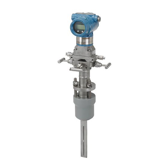
Emerson Rosemount 3051SF Series Quick Start Manual
Pressure transmitter and flowmeter with hart protocol
Hide thumbs
Also See for Rosemount 3051SF Series:
- Quick start manual (44 pages) ,
- Quick installation manual (36 pages) ,
- Quick start manual (32 pages)

Related Manuals for Emerson Rosemount 3051SF Series


Summary of Contents for Emerson Rosemount 3051SF Series
- Page 1 Quick Start Guide 00825-0100-4801, Rev NB December 2018 ™ Rosemount 3051S Series Pressure Transmitter and Rosemount 3051SF Series Flowmeter ® with HART Protocol...
-
Page 2: Table Of Contents
Refer to the Rosemount 3051S HART Reference Manual for more instruction. This document is also available electronically on Emerson.com/Rosemount. WARNING Explosions could result in death or serious injury. Installation of device in an explosive environment must be in accordance with appropriate local, national, and international standards, codes, and practices. - Page 3 December 2018 Quick Start Guide Rosemount 3051S Declaration of Conformity China RoHS..........49 ..............45 Quick Start Guide...
- Page 4 Quick Start Guide December 2018 Rosemount 3051S...
-
Page 5: Mount The Transmitter
December 2018 Quick Start Guide Mount the transmitter Liquid flow applications Procedure 1. Place taps to the side of the line. 2. Mount beside or below the taps. 3. Mount the transmitter so that the drain/vent valves are oriented upward. A. - Page 6 Only use bolts ™ supplied with the transmitter or sold by Emerson as spare parts. Figure 1-1 illustrates common transmitter assemblies with the bolt length required for proper transmitter assembly.
- Page 7 Table 1-1 . If bolt material is not shown in Table 1-1, contact the local Emerson representative for more information. Use the following bolt installation procedure: Procedure 1. Carbon steel bolts do not require lubrication and the stainless steel bolts are coated with a lubricant to ease installation.
- Page 8 Quick Start Guide December 2018 5. Verify the flange bolts are protruding through the sensor module before applying pressure (see Figure 1-2). Example Table 1-1: Torque Values for the Flange and Flange Adapter Bolts Bolt material Head markings Initial torque Final torque Carbon Steel 300 in-lb...
- Page 9 December 2018 Quick Start Guide O-rings with flange adapters WARNING Failure to install proper flange adapter O-rings may cause process leaks, which can result in death or serious injury. Only use the O-ring that is designed for its specific flange adapter. A.
- Page 10 Quick Start Guide December 2018 Figure 1-3: In-line Gage Transmitter A. Low side pressure port (under neck label) Rosemount 3051S...
-
Page 11: Consider Housing Rotation
December 2018 Quick Start Guide Consider housing rotation About this task To improve field access to wiring or to better view the optional LCD display: Procedure 1. Loosen the housing rotation set screw. 2. Turn the housing up to 180° left or right of its original (as shipped) position. -
Page 12: Set Switches And Jumpers
Quick Start Guide December 2018 Set switches and jumpers About this task If alarm and security adjustment option is not installed, the transmitter will operate normally with the default alarm condition alarm “high” and the security “off”. Procedure 1. Do not remove the transmitter covers in explosive atmospheres when the circuit is live. - Page 13 December 2018 Quick Start Guide Figure 3-2: Transmitter Switch and Jumper Configuration (Junction Box) A. Meter/adjustment module B. Security C. Alarm Quick Start Guide...
-
Page 14: Connect Wiring And Power Up
Quick Start Guide December 2018 Connect wiring and power up Procedure 1. Remove and discard orange conduit plugs. 2. Remove the housing cover labeled “Field Terminals.” Note Do not connect the power across the test terminals. Power could damage the test diode in the test connection. Twisted pairs yield best results. - Page 15 December 2018 Quick Start Guide Figure 4-1: Transmitter Wiring (Plantweb Housing) A. RL ≥ 250 Ω B. Power supply Figure 4-2: Transmitter Wiring (Junction Box Housing) A. RL ≥ 250 Ω B. Power supply Note Installation of the transient protection terminal block does not provide transient protection unless the Rosemount 3051S case is properly grounded.
- Page 16 Quick Start Guide December 2018 • Be trimmed close and insulated from touching the transmitter housing • Continuously connect to the termination point • Be connected to a good earth ground at the power supply end Figure 4-3: Wiring A. Insulate shield B.
- Page 17 December 2018 Quick Start Guide Cable type Recommend Madison AWM Style 2549 cable. Other comparable cable may be used as long as it has independent dual twisted shielded pair wires with an outer shield. The power wires must be 22 AWG minimum and the CAN communication wires must be 24 AWG minimum.
- Page 18 Quick Start Guide December 2018 Figure 4-4: Remote Mount Display Wiring Diagram (white) 24 AWG (blue) 24 AWG (black) 22 AWG (red) 22 AWG A. Remote mount display B. Junction box housing C. 4–20 mA Note Wire colors provided are per Madison AWM Style 2549 cable. Wire color may vary depending on cable selected.
- Page 19 December 2018 Quick Start Guide Figure 4-5: Rosemount 3051S Quick Connect Exploded View A. Straight field wireable connector (part number 03151-9063-0001), supplied by customer B. Right angle field wireable connector (part number 03151-9063-0002), supplied by customer C. Quick Connect housing D.
- Page 20 Quick Start Guide December 2018 Figure 4-6: Quick Connect Housing Pin-Out “+” “ ” A. Ground B. No connection Note For other wiring details, refer to pin-out drawing and the cordset manufacturer’s installation instructions. Conduit electrical connector wiring (option GE or GM) For Rosemount 3051S with conduit electrical connectors GE or GM, refer to the cordset manufacturer’s installation instructions for wiring details.
- Page 21 December 2018 Quick Start Guide Figure 4-7: Load Limitation 1387 1000 Operating Region 10.5 42.4 Voltage (Vdc) Maximum loop resistance = 43.5 x (power supply voltage – 10.5) The Field Communicator requires a minimum loop resistance of 250Ω for communication. Quick Start Guide...
-
Page 22: Verify Configuration
Quick Start Guide December 2018 Verify configuration Use any HART-compliant master to communicate with and verify configuration of the Rosemount 3051S. Field Communicator user interface Fast Key sequences vary with the device driver revision. Reference Table 5-1 for DD Rev. 8 or older. Reference Table 5-2 for DD Rev. - Page 23 December 2018 Quick Start Guide Table 5-1: Fast Key Sequences-Traditional Interface (Device Revision 6 or 7 and DD Revision 7) (continued) Function Fast Key sequence Analog Output Alarm 1, 4, 2, 7, 6 Direction Analog Output Trim 1, 2, 3, 2 Burst Mode On/Off 1, 4, 3, 3, 3 Burst Options...
- Page 24 Quick Start Guide December 2018 Table 5-1: Fast Key Sequences-Traditional Interface (Device Revision 6 or 7 and DD Revision 7) (continued) Function Fast Key sequence Sensor Temperature 1, 1, 4 Sensor Trim 1, 2, 3, 3 Sensor Trim Points 1, 2, 3, 3, 5 Status 1, 2, 1, 2 ✓...
- Page 25 December 2018 Quick Start Guide Table 5-2: Fast Key Sequences-Device Dashboard (Device Revision 7 and DD Revision 9) (continued) Function Fast Key sequence Loop Test 3, 5, 1 Lower Sensor Trim 3, 4, 1, 2 Message 2, 2, 5, 6 Range Values 2, 2, 1, 3 Scaled D/A Trim (4–20 mA...
-
Page 26: Trim The Transmitter
Quick Start Guide December 2018 Trim the transmitter Transmitters are shipped fully calibrated per request or by the factory default of full scale (lower range value = zero, upper range value = upper range limit). Zero trim Prerequisites Choose your trim procedure 1. - Page 27 December 2018 Quick Start Guide Figure 6-1: Transmitter Adjustment Buttons (Plantweb Housing) A. Zero B. Span Figure 6-2: Transmitter Adjustment Buttons (Junction Box Housing) A. Zero B. Span Quick Start Guide...
-
Page 28: Safety Instrumented Systems Installation
Quick Start Guide December 2018 Safety instrumented systems installation For safety certified installations, refer to the Rosemount 3051S Reference Manual for installation procedure and system requirements. Rosemount 3051S... -
Page 29: Rosemount 3051S/3051Sfx/3051S-Ers Product Certifications
A copy of the EU Declaration of Conformity can be found at the end of the Quick Start Guide. The most recent revision of the EU Declaration of Conformity can be found at Emerson.com/Rosemount. Ordinary Location Certification As standard, the transmitter has been examined and tested to determine that... - Page 30 Quick Start Guide December 2018 Special Condition for Safe Use: 1. The Model 3051S/3051S-ERS Pressure Transmitter contains aluminum and is considered to constitute a potential risk of ignition by impact or friction. Care must be taken into account during installation and use to prevent impact and friction.
- Page 31 December 2018 Quick Start Guide Standards CAN/CSA C22.2 No. 0-10, CSA Std C22.2 No. 25-1966, CSA Std C22.2 No. 30-M1986, CAN/CSA C22.2 No. 94-M91, CSA Std C22.2 No. 142-M1987, CSA Std C22.2 No. 157-92, ANSI/ISA 12.27.01-2003, CSA Std C22.2 No. 60529:05 Markings Intrinsically Safe Class I, Division 1;...
- Page 32 Quick Start Guide December 2018 environmental conditions to which the diaphragm will be subjected. The manufacturer's instructions for installation and maintenance shall be followed in detail to assure safety during its expected lifetime. 2. Flameproof joints are not intended for repair. 3.
- Page 33 December 2018 Quick Start Guide 2. The terminal pins of the Model 3051S SuperModule must be provided with a degree of protection of at least IP20 in accordance with IEC/EN 60529. 3. The Model 3051S enclosure may be made of aluminum alloy and given a protective polyurethane paint finish;...
- Page 34 Quick Start Guide December 2018 Special Conditions for Safe Use (X): 1. Cable entries must be used which maintain the ingress protection of the enclosure to at least IP66. 2. Unused cable entries must be filled with suitable blanking plugs which maintain the ingress protection of the enclosure to at least IP66.
- Page 35 December 2018 Quick Start Guide Special Conditions for Safe Use (X): 1. This device contains a thin wall diaphragm less than 1 mm thickness that forms a boundary between EPL Ga (process connection) and EPL Gb (all other parts of the equipment). The model code and datasheet are to be consulted for details of the diaphragm material.
- Page 36 Quick Start Guide December 2018 Table 8-5: Input Parameters SuperModule 30 V 300 mA 1.0 W 30 nF 3051S...A; 3051SF…A; 30 V 300 mA 1.0 W 12 nF 3051SAL…C 3051S…F; 3051SF…F 30 V 300 mA 1.3 W 3051S …A…M7, M8, or 30 V 300 mA 1.0 W...
- Page 37 December 2018 Quick Start Guide Table 8-6: Input Parameters (continued) 3051S…F; 3051SF…F 30 V 300 mA 1.3 W 3051S …A…M7, M8, or 30 V 300 mA 1.0 W 12 nF 60 µH M9; 3051SF …A…M7, M8, or M9; 3051SAL…C… M7, M8, or M9 3051SAL or 3051SAM 30 V...
- Page 38 Quick Start Guide December 2018 Special Conditions for Safe Use (X): 1. The Model 3051S Transmitters fitted with transient protection are not capable of withstanding the 500 V test as defined in Clause 6.3.13 of EN 60079-11:2012. This must be taken into account during installation.
- Page 39 December 2018 Quick Start Guide Markings Ex nA IIC T5 Gc,(–40 °C ≤ T ≤ +85 °C) Special Condition for Safe Use (X): 1. The equipment is not capable of withstanding the 500 V insulation test required by clause 6.5 of EN 60079-15:2010. This must be taken into account when installing the equipment.
- Page 40 Quick Start Guide December 2018 2. The Model 701PBKKF Power Module may be replaced in a hazardous area. The Power Module has a surface resistivity greater than 1 GΩ and must be properly installed in the wireless device enclosure. Care must be taken during transportation to and from the point of installation to prevent electrostatic charge buildup.
- Page 41 December 2018 Quick Start Guide Markings 3051S: Ex d IIC T6…T4; Ex tD A20 T105 °C T 95 °C; IP66 3051SFx: Ex d IIC T4~T6 Ga/Gb; Ex tD A20 IP66 T105 °CT °C; IP66 3051S-ERS: Ex d IIC T4~T6 Ga/Gb 8.6.2 I3 China Intrinsic Safety Certificate 3051S: GYJ16.1250X[Mfg USA, China, Singapore] 3051SFx: GYJ16.1465X [Mfg USA, China, Singapore]...
- Page 42 Quick Start Guide December 2018 8.7.3 IN Technical Regulation Customs Union (EAC) Intrinsic Safety Certificate: RU C-US.AA87.B.00378 Markings: 0Ex ia IIC T4 Ga X Japan 8.8.1 E4 Japan Flameproof Certificate TC15682, TC15683, TC15684, TC15685, TC15686, TC15687, TC15688, TC15689, TC15690, TC17099, TC17100, TC17101, TC17102, TC18876 3051ERS: TC20215, TC20216, TC20217, TC20218, TC20219, TC20220, TC20221...
- Page 43 December 2018 Quick Start Guide 8.9.2 IP Republic of Korea Intrinsic Safety Certificate 12-KB4BO-0202X [HART - Mfg USA],12-KB4BO-0204X [Fieldbus - Mfg USA], 12-KB4BO-0203X [HART - Mfg Singapore], 13- KB4BO-0296X [Fieldbus - Mfg Singapore] Markings Ex ia IIC T4 8.10 Combinations Combination of E1, I1, N1, and ND Combination of E2 and I2 Combination of E5 and I5...
- Page 44 Quick Start Guide December 2018 8.11.3 SDN Det Norske Veritas (DNV) Type Approval Certificate TAA00000K9 Intended Use Det Norske Veritas' Rules for Classification of Ships, High Speed & Light Craft, and Det Norske Veritas' Offshore Standards Application Location classes Type 3051S Temperature Humidity...
- Page 45 December 2018 Quick Start Guide Rosemount 3051S Declaration of Conformity Quick Start Guide...
- Page 46 Quick Start Guide December 2018 Rosemount 3051S...
- Page 47 December 2018 Quick Start Guide Quick Start Guide...
- Page 48 Quick Start Guide December 2018 Rosemount 3051S...
- Page 49 December 2018 Quick Start Guide China RoHS Rosemount 3051S China RoHS List of Rosemount 3051S Parts with China RoHS Concentration above MCVs / Hazardous Substances Hexavalent Polybrominated Polybrominated Part Name Lead Mercury Cadmium Chromium biphenyls diphenyl ethers (Pb) (Hg) (Cd) (Cr +6) (PBB) (PBDE)
- Page 50 Quick Start Guide December 2018 Rosemount 3051S...
- Page 51 December 2018 Quick Start Guide Quick Start Guide...
- Page 52 The Emerson logo is a Facebook.com/Rosemount trademark and service mark of Emerson Electric Youtube.com/user/ Co. Rosemount is mark of one of the Emerson RosemountMeasurement family of companies. All other marks are the Google.com/+RosemountMeasurement property of their respective owners.
Need help?
Do you have a question about the Rosemount 3051SF Series and is the answer not in the manual?
Questions and answers