
Related Manuals for Emerson Rosemount X-STREAM O2 Transmitter


Summary of Contents for Emerson Rosemount X-STREAM O2 Transmitter
- Page 1 Instruction Manual IM-106-910C, Rev. 1.0 November 2009 Hazardous Area X-STREAM O Combustion Flue Gas Transmitter http://www.raihome.com...
- Page 3 HIGHLIGHTS OF CHANGES Effective November 30, 2009 Rev 1.0 Page Summary General Updates Updated master Table of Contents, Section Tables of Content, and Index. Updated IM page header revision level and release date throughout manual. Page v Revised text of 2nd step 3 and Xi Mounting description of Installation Summary. Page 1-6 Added new descriptive onto end of first paragraph.
-
Page 5: Table Of Contents
Hazardous Area Instruction Manual IM-106-910C, Rev. 1.0 X-STREAM O Transmitter November 2009 Table of Contents Essential Instructions........i SECTION i Preface . - Page 6 Hazardous Area Instruction Manual IM-106-910C, Rev. 1.0 X-STREAM O Transmitter November 2009 SECTION 3 Verify Installation ......... 3-1 Configuration of Transmitter .
- Page 7 Hazardous Area Instruction Manual IM-106-910, Rev. 1.0 X-STREAM O Transmitter November 2009 SECTION 6 Overview ..........6-1 Maintenance and Service Maintenance Intervals .
- Page 8 Hazardous Area Instruction Manual IM-106-910C, Rev. 1.0 X-STREAM O Transmitter November 2009 TOC-4...
-
Page 9: Essential Instructions
November 2009 X-STREAM Oxygen Transmitters READ THIS PAGE BEFORE PROCEEDING! ESSENTIAL Emerson Process Management designs, manufactures and tests its products to meet many national November 2009and international standards. Because INSTRUCTIONS these instruments are sophisticated technical products, you MUST properly install, use, and maintain them to ensure they continue to operate within their normal specifications. - Page 10 Hazardous Area Instruction Manual IM-106-910C, Rev. 1.0 X-STREAM O Transmitter November 2009...
-
Page 11: Preface
Hazardous Area Instruction Manual IM-106-910C, Rev. 1.0 X-STREAM O Transmitter November 2009 Section i Introduction Preface ......... page iii Definitions . -
Page 12: Symbols
Hazardous Area Instruction Manual IM-106-910C, Rev. 1.0 X-STREAM O Transmitter November 2009 SYMBOLS EARTH (GROUND) TERMINAL PROTECTIVE CONDUCT OR TERMINAL RISK OF ELECTRICAL SHOCK WARNING: REFER TO INSTRUCTION MANUAL NOTE TO USERS The number in the lower right corner of each illustration in this publication is a manual illustration number. - Page 13 1. HART communications through a 375 Field Communicator 2. HART communications through Emerson's AMS 3. An optional Xi Enhanced Interface. The Xi can act as interface to one or two X-STREAM probes. The Xi also carries advanced features such as...
-
Page 14: Quick Start Guide For X-Stream Systems
Transmitter. 3. Connect HART communications, either through a handheld communicator like the Rosemount 375 Field Communicator, or through Emerson's AMS Suite PC software, or on an AMS-aware DCS. NOTE For a transmitter with optional Xi Enhanced Interface, the 375 Field Communicator must be connected only to the 4 to 20 mA signal loop between the Xi and the control room or data acquisition system. -
Page 15: Quick Reference Guide Manual Calibration Instructions
Hazardous Area Instruction Manual IM-106-910C, Rev. 1.0 X-STREAM O Transmitter November 2009 Figure 1. X-STREAM Integral Electronics Wiring Diagram QUICK REFERENCE Performing a Manual Calibration with a 375 Field Communicator GUIDE MANUAL Use the following procedure to perform a calibration using the 375 Field CALIBRATION Communicator. -
Page 16: Field Communicator Fast Key Sequences
In addition to the CSC, you may also contact Field Watch. Field Watch coordinates Emerson Process Management’s field service throughout the U.S. and abroad. Phone: 1-800-654-RSMT (1-800-654-7768) Emerson Process Management may also be reached via the Internet through e-mail and the World Wide Web: e-mail: GAS.CSC@emerson.com World Wide Web: www.raihome.com... -
Page 17: Component Checklist
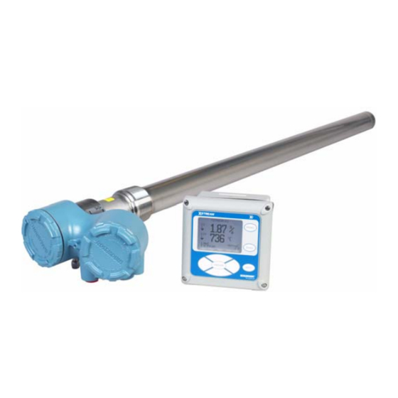
Hazardous Area Instruction Manual IM-106-910C, Rev. 1.0 X-STREAM O Transmitter November 2009 Section 1 Description and Specifications Component Checklist ......page 1-1 System Overview . - Page 18 Hazardous Area Instruction Manual IM-106-910C, Rev. 1.0 X-STREAM O Transmitter November 2009 Figure 1-1. Typical System Package 1. Instruction Manual 2. Hazardous Area X-STREAM O Transmitter with Integral Electronics (or optional DR Probe) 3. Weld Plate 4. Traditional Architecture Cable (Optional) 5.
-
Page 19: System Description
Hazardous Area Instruction Manual IM-106-910C, Rev. 1.0 X-STREAM O Transmitter November 2009 The Hazardous Area X-STREAM O Transmitter is designed to measure the System Description net concentration of oxygen in an industrial combustion process; i.e., the oxygen remaining after all fuels have been burned. The probe utilizes an "in situ"... -
Page 20: System Features
Hazardous Area Instruction Manual IM-106-910C, Rev. 1.0 X-STREAM O Transmitter November 2009 The sensor cell will read the O concentration as a percentage of the total volume of flue gases including water vapor. Therefore, it may be considered an analysis on a "wet" basis. In comparison with older methods such as the portable apparatus, which provides an analysis on a "dry"... - Page 21 Hazardous Area Instruction Manual IM-106-910C, Rev. 1.0 X-STREAM O Transmitter November 2009 Figure 1-2. Hazardous Area X-STREAM with Integral Transmitter Electronics Figure 1-3. Hazardous Area X-STREAM with Integral Transmitter Electronics and Optional Xi Enhanced Interface Integral Transmitter Electronics, HART and Xi Communications The optional Xi enhanced interface (Figure 1-3) provides a local display/key- pad for setting up, calibrating, and displaying O , and for diagnosing probe...
- Page 22 Hazardous Area Instruction Manual IM-106-910C, Rev. 1.0 X-STREAM O Transmitter November 2009 Traditional Architecture, HART and Xi Communications Some customers prefer not to mount electronics onto the probe, so a "tradi- tional architecture" version is offered. This probe sends raw millivolt signals via a 7-conductor cable to an Xi electronics (Figure 1-4) which does all heater control and signal conditioning in addition to it's display/keypad functions.
-
Page 23: Automatic Calibration
X-STREAM. The DD software will be supplied with many Model 375 units but can also be programmed into existing units at most Emerson Process Management service offices. See Section 4, Startup and Operation, for additional information. • Personal Computer (PC) - The use of a personal computer requires AMS software available from Emerson Process Management. - Page 24 Graphic License for operation with the Hazardous Area X-STREAM O Transmitter. The AMS software must be upgraded to AMS 8.0 or above. Contact Emerson Process Management’s Global Service Center (GSC) at 1-800-833-8314 to upgrade the 375 Field Communicator software to System Software 2.0 with Graphic License.
-
Page 25: Probe Options
Hazardous Area Instruction Manual IM-106-910C, Rev. 1.0 X-STREAM O Transmitter November 2009 PROBE OPTIONS Diffusion Elements Snubber Diffusion Assembly The standard snubber diffusion assembly (Figure 1-7) is satisfactory for most applications, however the snubber diffuser should not be used in flue gas °... -
Page 26: Specifications
Hazardous Area Instruction Manual IM-106-910C, Rev. 1.0 X-STREAM O Transmitter November 2009 SPECIFICATIONS Measurement Specifications Net O Range: 0 to 50% O user scalable -2 to 50% O user scalable with stoichiometer Accuracy in Oxidizing Conditions: ±0.75% of reading or 0.05% O , whichever is greater Lowest Detectable Limit: 0.01% O... - Page 27 Internally powered input to remove heater power. Actuated via dry contact output from user’s flame scanner. Emerson Process Management has satisfied all obligations coming from the European legislation to harmonize the product requirements in Europe. All static performance characteristics are with operating variables constant. Specifications subject to change without notice.
- Page 28 Hazardous Area Instruction Manual IM-106-910C, Rev. 1.0 X-STREAM O Transmitter November 2009 Table 1-1. Product Matrix, Hazardous Area O Transmitter with Process End Flame Arrestor XS-O2XPFA X-STREAM O Transmitter - Flameproof - with Process End Flame Arrestor Code Probe Type Snubber Diffuser, Standard Sensing Cell Snubber Diffuser, Acid-Resistant Stoichiometer Sensing Cell Ceramic Diffuser, Standard Sensing Cell...
- Page 29 Hazardous Area Instruction Manual IM-106-910C, Rev. 1.0 X-STREAM O Transmitter November 2009 Table 1-2. Product Matrix, Hazardous Area O Transmitter without Process End Flame Arrestor XS-O2XP X-STREAM O Transmitter - Flameproof - No Process End Flame Arrestor Code Probe Type Snubber Diffuser, Standard Sensing Cell Snubber Diffuser, Acid-Resistant Stoichiometer Sensing Cell Ceramic Diffuser, Standard Sensing Cell...
- Page 30 Hazardous Area Instruction Manual IM-106-910C, Rev. 1.0 X-STREAM O Transmitter November 2009 Table 1-3. Product Matrix, Xi Interface and Advanced Feature Electronics (For use in non-hazardous areas only.) X-STREAM O Remote Code Remote Type Single Channel X-STREAM Interface Single Channel X-STREAM Interface, accepting a loss-of-flame input to remove heater power with flame status relay Dual Channel X-STREAM Interface Single Channel X-STREAM Traditional Architecture for 120V Probes Single Channel X-STREAM Traditional Architecture for 44V Probes...
- Page 31 Hazardous Area Instruction Manual IM-106-910C, Rev. 1.0 X-STREAM O Transmitter November 2009 Table 1-4. Product Matrix, X-STREAM O Autocalibration Accessories (For use in non-hazardous areas only.) XSO2CAL X-STREAM O Autocalibration Accessories Code Single Probe Sequencers Autocalibration Options None SPS 4001B Single Probe Sequencer, general purpose NEMA 4X, includes check valve for probe Code Intelligent Multiprobe Sequencers (IMPS) None...
- Page 32 Hazardous Area Instruction Manual IM-106-910C, Rev. 1.0 X-STREAM O Transmitter November 2009 1-16...
- Page 33 Hazardous Area Instruction Manual IM-106-910C, Rev. 1.0 X-STREAM O Transmitter November 2009 Section 2 Installation System Considerations ......page 2-2 Hazardous Area Considerations .
-
Page 34: System Considerations
Hazardous Area Instruction Manual IM-106-910C, Rev. 1.0 X-STREAM O Transmitter November 2009 To maintain explosion-proof protection the X-STREAM O Transmitter Model XS-O2XP must not be installed in processes classified as hazardous areas. The model XS-O2XP Transmitter is for use in non-hazardous areas only. The Hazardous Area X-STREAM O Transmitter and probe with abrasive shield are heavy. - Page 35 Hazardous Area Instruction Manual IM-106-910C, Rev. 1.0 X-STREAM O Transmitter November 2009 Figure 2-1. Typical System Installation If the calibration gas bottles will be permanently connected a check valve is required next to the calibration fittings on the probe. This check valve is to prevent breathing of the calibration gas line and subsequent flue gas condensation and corrosion.
-
Page 36: Hazardous Area Considerations
Hazardous Area Instruction Manual IM-106-910C, Rev. 1.0 X-STREAM O Transmitter November 2009 HAZARDOUS AREA The Hazardous Area X-STREAM O probe system (Figure 2-2) is an in-situ device. The process end of the probe places a heated (736°C) sensing cell CONSIDERATIONS directly into the process;... -
Page 37: Mechanical Installation
Hazardous Area Instruction Manual IM-106-910C, Rev. 1.0 X-STREAM O Transmitter November 2009 MECHANICAL INSTALLATION Selecting Location 1. Figure 2-3 through Figure 2-10 provide reference illustrations for the mechanical installations of the equipment. 2. The location of the X-STREAM O Transmitter in the stack or flue is most important for maximum accuracy in the oxygen analyzing process. -
Page 38: Probe Installation
Hazardous Area Instruction Manual IM-106-910C, Rev. 1.0 X-STREAM O Transmitter November 2009 Figure 2-3. Probe Installation Details Probe Installation The probe was specially packaged to prevent breakage due to handling. Do not remove the padding material from the probe until immediately before installation. - Page 39 Hazardous Area Instruction Manual IM-106-910C, Rev. 1.0 X-STREAM O Transmitter November 2009 1. Ensure all components are available to install the X-STREAM O probe. Refer to the probe installation details in Figure 2-3. 2. Standard mounting uses a 6-inch square weld plate with a 2-½ inch NPT probe port welded to the stack or duct wall.
- Page 40 Hazardous Area Instruction Manual IM-106-910C, Rev. 1.0 X-STREAM O Transmitter November 2009 Figure 2-6. OXT/WC Retrofit Mounting Flange (threads onto probe) Figure 2-7. Optional Adapter Plate...
- Page 41 Hazardous Area Instruction Manual IM-106-910C, Rev. 1.0 X-STREAM O Transmitter November 2009 5. Insert probe through the opening in the mounting flange and bolt the unit to the flange. Do not thread the probe by turning the blue electronics housing. Use a pipe wrench on the probe tube between the housing and threaded fitting.
-
Page 42: Optional Xi Enhanced Interface Installation
Hazardous Area Instruction Manual IM-106-910C, Rev. 1.0 X-STREAM O Transmitter November 2009 Figure 2-8. Installation with Drip Loop and Insulation Removal Optional Xi Enhanced The optional Xi Enhanced Interface is available in a panel mounting, wall mounting, or pipe mounting configuration. Refer to Figure 2-9 or Figure 2-10 Interface Installation for the panel, wall, or pipe mounting details. - Page 43 Hazardous Area Instruction Manual IM-106-910C, Rev. 1.0 X-STREAM O Transmitter November 2009 Figure 2-9. Xi Enhanced Interface - Panel Mounting Details 2-11...
- Page 44 Hazardous Area Instruction Manual IM-106-910C, Rev. 1.0 X-STREAM O Transmitter November 2009 Figure 2-10. Xi Enhanced Interface - Wall/Surface and Pipe Mounting Details 2-12...
-
Page 45: Electrical Installation
Hazardous Area Instruction Manual IM-106-910C, Rev. 1.0 X-STREAM O Transmitter November 2009 ELECTRICAL All wiring must conform to local and national codes. Multiple wiring diagrams are shown in this section. Always refer to the diagrams that apply to your INSTALLATION transmitter configuration and disregard all other wiring diagrams. - Page 46 Hazardous Area Instruction Manual IM-106-910C, Rev. 1.0 X-STREAM O Transmitter November 2009 NOTE If metal conduit is used with the Xi Enhanced Interface the conduit should be reliably bonded to protective earth. The grounding plate inside the Xi is not bonded to PE and does not provide adequate grounding.
-
Page 47: Optional Xi Enhanced Interface
Hazardous Area Instruction Manual IM-106-910C, Rev. 1.0 X-STREAM O Transmitter November 2009 Optional Xi Enhanced 1. Remove cover screws from the front cover of the Xi Enhanced Interface. Swing down the front cover of the interface box. Interface 2. Pull out the I/O board on the right-hand side of the card rack inside the Xi Enhanced Interface. -
Page 48: Power Connections - Xi Enhanced Interface
Hazardous Area Instruction Manual IM-106-910C, Rev. 1.0 X-STREAM O Transmitter November 2009 4. Terminate the shield of the 4-20 mA signal wires at the designated ground terminal of the Xi Enhanced Interface. Do not allow bare shield wires to contact the circuit boards. Insulate the shield wires prior to termination. -
Page 49: Optional Flame Safety Interlock
IM-106-910C, Rev. 1.0 X-STREAM O Transmitter November 2009 A flame safety interlock by Emerson Process Management is available for Optional Flame Safety heater power disconnect whenever there is a loss of the process flame or a Interlock heater runaway condition (heater over-temperature) in the X-STREAM O Transmitter. - Page 50 Hazardous Area Instruction Manual IM-106-910C, Rev. 1.0 X-STREAM O Transmitter November 2009 1. Run the 7-conductor cable between the Hazardous Area X-STREAM traditional architecture probe and the installation site for Xi Enhanced Interface. Use new cable conduit or trough as needed. 2.
- Page 51 Hazardous Area Instruction Manual IM-106-910C, Rev. 1.0 X-STREAM O Transmitter November 2009 5. Connect the cable lead wires to the probe connector, Figure 2-17. 6. At the Xi Enhanced Interface, connect the cable leads to the connectors on the transmitter I/O board as indicated in Figure 2-18. Figure 2-17.
- Page 52 Hazardous Area Instruction Manual IM-106-910C, Rev. 1.0 X-STREAM O Transmitter November 2009 Figure 2-18. Transmitter Board Connections at Xi - Traditional Architecture Figure 2-19. DR Probe - Wiring Diagram 2-20...
-
Page 53: Direct Replacement (Dr) Probe Connections
Hazardous Area Instruction Manual IM-106-910C, Rev. 1.0 X-STREAM O Transmitter November 2009 Direct Replacement (DR) A direct replacement probe is available for connection to an existing electronics package. Use the following procedure to connect a DR probe to Probe Connections the transmitter electronics. - Page 54 Hazardous Area Instruction Manual IM-106-910C, Rev. 1.0 X-STREAM O Transmitter November 2009 Figure 2-20. DR Probe Wired to the YEW Electronics 2-22...
-
Page 55: Pneumatic Installation
Hazardous Area Instruction Manual IM-106-910C, Rev. 1.0 X-STREAM O Transmitter November 2009 PNEUMATIC INSTALLATION Reference Air Package After the X-STREAM is installed, connect the reference air set to the X-STREAM unit. Refer to the schematic diagram in Figure 2-21 and the mounting dimensions in Figure 2-22 for a locally assembled reference air supply. - Page 56 Hazardous Area Instruction Manual IM-106-910C, Rev. 1.0 X-STREAM O Transmitter November 2009 Figure 2-23. Manual Calibration Panel 2-24...
-
Page 57: Calibration Gas
Hazardous Area Instruction Manual IM-106-910C, Rev. 1.0 X-STREAM O Transmitter November 2009 Reference air components are included in the optional Manual Calibration Panel (Figure 2-23), the SPS 4001 Single Probe Autocalibration Sequencer, and the IMPS 4000 Intelligent Multiprobe Test Gas Sequencer. NOTES The optional SPS 4001B or IMPS 4000 Sequencer can only be used when the Xi Enhanced Interface option is selected. -
Page 58: Transmitter
Hazardous Area Instruction Manual IM-106-910C, Rev. 1.0 X-STREAM O Transmitter November 2009 2-26... -
Page 59: Verify Installation
Hazardous Area Instruction Manual IM-106-910C, Rev. 1.0 X-STREAM O Transmitter November 2009 Section 3 Configuration of Hazardous Area X-STREAM O Transmitter Verify Installation ....... . page 3-1 Transmitter . -
Page 60: Configuration (If Equipped)
Hazardous Area Instruction Manual IM-106-910C, Rev. 1.0 X-STREAM O Transmitter November 2009 Refer to Figure 3-1 for the configuration of jumpers JP1 through JP8. The Xi Configuration jumper configuration for your I/O board depends on the X-STREAM system (if equipped) design and system components used in your installation. -
Page 61: Alarm Relay Output Configuration
Hazardous Area Instruction Manual IM-106-910C, Rev. 1.0 X-STREAM O Transmitter November 2009 Set Test Gas Values Using Xi Enhanced Interface Keypad/Display 1. Press the MENU button once. 2. From the main menu, select PROBE 1. 3. From PROBE 1, select DETAILED SETUP. 4. -
Page 62: Analog Output Configuration
Hazardous Area Instruction Manual IM-106-910C, Rev. 1.0 X-STREAM O Transmitter November 2009 4. From ALARM RELAY, select as follows: Alm Relay1 - Alarm 1 mode Alm Relay2 - Alarm 2 mode Low O2 Alm SP - Low O2 alarm setpoint High Temp Alm SP - High temperature alarm setpoint 5. -
Page 63: Autocalibration Setup
Hazardous Area Instruction Manual IM-106-910C, Rev. 1.0 X-STREAM O Transmitter November 2009 Configuring the Analog Output with the Xi Enhanced Interface Keypad/Display 1. Press the MENU button once. 2. From the main menu, select PROBE 1. 3. From PROBE 1, select DETAILED SETUP. 4. -
Page 64: Extended Process Temperature Range To 800°C (1472°F)
Failure to do so will cause a false analog output signal to the DCS. NOTE For enhanced software feature option upgrades or to enable the feature to duplicate the existing configuration, contact Emerson Process Management at 1-800-433-6076. Reference the following: 6A00269G01... -
Page 65: Programmable Reference
Hazardous Area Instruction Manual IM-106-910C, Rev. 1.0 X-STREAM O Transmitter November 2009 NOTE Make sure the DCS is configured for the same range as the Xi. For instance: -1% O to 10% O The zirconium oxide sensing technology has historically measured process Programmable oxygen by using ambient or instrument air as a reference (20.95% oxygen). - Page 66 Hazardous Area Instruction Manual IM-106-910C, Rev. 1.0 X-STREAM O Transmitter November 2009...
-
Page 67: Overview
Hazardous Area Instruction Manual IM-106-910C, Rev. 1.0 X-STREAM O Transmitter November 2009 Section 4 Startup and Operation Overview ........page 4-1 Startup . -
Page 68: Startup Display
Hazardous Area Instruction Manual IM-106-910C, Rev. 1.0 X-STREAM O Transmitter November 2009 The transmitter probe will take approximately 45 minutes to warm up to the ° C heater setpoint. The 4-20 mA signal will remain at a default value of 3.5 mA through this warm-up period. -
Page 69: Error Conditions
Hazardous Area Instruction Manual IM-106-910C, Rev. 1.0 X-STREAM O Transmitter November 2009 Error Conditions If there is an error condition at startup, an alarm message will be displayed. Refer to Section 5: Troubleshooting to determine the cause of the error. Clear the error and cycle power. - Page 70 Hazardous Area Instruction Manual IM-106-910C, Rev. 1.0 X-STREAM O Transmitter November 2009 Figure 4-2. Xi Menu, Sheet 1 of 3...
- Page 71 Hazardous Area Instruction Manual IM-106-910C, Rev. 1.0 X-STREAM O Transmitter November 2009 Figure 4-2. Xi Menu, Sheet 2 of 3...
- Page 72 Hazardous Area Instruction Manual IM-106-910C, Rev. 1.0 X-STREAM O Transmitter November 2009 Figure 4-2. Xi Menu, Sheet 3 of 3...
-
Page 73: System Parameter Descriptions
Hazardous Area Instruction Manual IM-106-910C, Rev. 1.0 X-STREAM O Transmitter November 2009 SYSTEM PARAMETER Among the parameters available through the Xi and 375 Field Communicator menus are a number of "System Parameters". The system parameters define DESCRIPTIONS variables that configure the Xi in the transmitter system. System parameters are described in the following table. -
Page 74: Probe Parameter Descriptions
Hazardous Area Instruction Manual IM-106-910C, Rev. 1.0 X-STREAM O Transmitter November 2009 PROBE PARAMETER Among the parameters available through the Xi and 375 Communicator menus are a number of "Probe Parameters". The probe parameters define DESCRIPTIONS variables that configure a specific probe in the transmitter system. Probe parameters are described in the following table. - Page 75 Hazardous Area Instruction Manual IM-106-910C, Rev. 1.0 X-STREAM O Transmitter November 2009 PARAMETER NAME UNITS PARAMETER DESCRIPTION Prev Cal Imp Previous Cell Impedance. This is the sensor resistance that was calculated as a result of previous successful calibration. There are ten calibration results. Index 1 is the most recent and Index 10 is the least recent sensor resistance measured.
-
Page 76: Operation Via Hart/Ams
Transmitter. The AMS software must be upgraded to AMS 8.0 or above for operation with the Hazardous Area X-STREAM O Transmitter. Contact Emerson Process Management’s Global Service Center (GSC) at 1-800-833-8314 to upgrade the 375 Field Communicator software to System Software 2.0 with Graphic License. - Page 77 Hazardous Area Instruction Manual IM-106-910C, Rev. 1.0 X-STREAM O Transmitter November 2009 ≥ Figure 4-3. Signal Line Connections, 250 Ohms Load Resistance Signals are not intrinsically safe. In an explosive atmosphere do not make connections to the 375 Field Communicator’s serial port, 4-20 mA signal line, or NiCad recharger jack. Using the supplied lead set, connect the 375 Field Communicator in parallel with the X-STREAM.
- Page 78 Hazardous Area Instruction Manual IM-106-910C, Rev. 1.0 X-STREAM O Transmitter November 2009 Figure 4-4. 375 Field Communicator Connection at the O Transmitter 4-12...
- Page 79 Hazardous Area Instruction Manual IM-106-910C, Rev. 1.0 X-STREAM O Transmitter November 2009 Method 2, For Load Resistance < 250 ohms Refer to Figure 4-5 and the following steps to connect the 375 Field Commu- nicator to a signal line with < 250 ohms load resistance. Signals are not intrinsically safe.
-
Page 80: Field Communicator Signal Line Connections
Hazardous Area Instruction Manual IM-106-910C, Rev. 1.0 X-STREAM O Transmitter November 2009 Whenever the Hazardous Area X-STREAM O Transmitter includes the Xi Field Communicator Enhanced Interface option, be sure to connect the 375 Field Communicator Signal Line Connections only to the 4 to 20 mA signal loop wiring between the Xi Enhanced Interface (with Xi) and the control room or data acquisition system as shown in Figure 4-6. -
Page 81: Field Communicator Menu Trees
Hazardous Area Instruction Manual IM-106-910C, Rev. 1.0 X-STREAM O Transmitter November 2009 When the 375 Field Communicator is connected as shown in Figure 4-3, Field Communicator Figure 4-4, or Figure 4-5, refer to Figure 4-7 for the 375 Field Communicator Menu Trees Transmitter menu tree. - Page 82 Hazardous Area Instruction Manual IM-106-910C, Rev. 1.0 X-STREAM O Transmitter November 2009 Figure 4-7. 375 Field Communicator Transmitter Menu Tree (Sheet 1 of 2) 4-16...
- Page 83 Hazardous Area Instruction Manual IM-106-910C, Rev. 1.0 X-STREAM O Transmitter November 2009 Figure 4-7. 375 Field Communicator Transmitter Menu Tree (Sheet 2 of 2) 4-17...
- Page 84 Hazardous Area Instruction Manual IM-106-910C, Rev. 1.0 X-STREAM O Transmitter November 2009 Figure 4-8. 375 Field Communicator Xi Menu Tree (Sheet 1 of 2) 4-18...
- Page 85 Hazardous Area Instruction Manual IM-106-910C, Rev. 1.0 X-STREAM O Transmitter November 2009 Figure 4-8. 375 Field Communicator Xi Menu Tree (Sheet 2 of 2) 4-19...
-
Page 86: Calibration - General
Hazardous Area Instruction Manual IM-106-910C, Rev. 1.0 X-STREAM O Transmitter November 2009 New O cells may operate for more than a year without requiring calibration, CALIBRATION - but older cells may require recalibration every few weeks as they near the end GENERAL of their life. -
Page 87: O 2 Calibration Without Xi
Hazardous Area Instruction Manual IM-106-910C, Rev. 1.0 X-STREAM O Transmitter November 2009 For systems with configuration 1, shown in Figure 4-9, use the following Calibration without Xi procedure to perform a calibration using the 375 Field Communicator. If necessary, use the menu tree in Figure 4-7 for reference. NOTE To select a menu item, either use the up and down arrow keys to scroll to the menu item and press the right arrow key or use the number keypad to select... -
Page 88: O 2 Calibration With Xi
Hazardous Area Instruction Manual IM-106-910C, Rev. 1.0 X-STREAM O Transmitter November 2009 4. Return to the SYSTEM menu and select the last menu item, CALIBRATION, to access the CALIBRATION menu. 5. From the O CALIBRATION options, select Start Cal to start the O calibration procedure. -
Page 89: D/A Trim
Hazardous Area Instruction Manual IM-106-910C, Rev. 1.0 X-STREAM O Transmitter November 2009 7. In the first O2 CAL screen, a "Loop should be removed from automatic control" warning appears. Remove the Hazardous Area X-STREAM O Transmitter from any automatic control loops to avoid a potentially dan- gerous operating condition and press OK. -
Page 90: D/A Trim With Xi
Hazardous Area Instruction Manual IM-106-910C, Rev. 1.0 X-STREAM O Transmitter November 2009 For systems with configuration 2, shown in Figure 4-10, use the handheld 375 D/A Trim with Xi Field Communicator to access the D/A trim procedure according to the instructions that follow. -
Page 91: Overview Of Operating Principles
Hazardous Area Instruction Manual IM-106-910C, Rev. 1.0 X-STREAM O Transmitter November 2009 Section 5 Troubleshooting Overview of Operating Principles ....page 5-1 General . -
Page 92: General
Hazardous Area Instruction Manual IM-106-910C, Rev. 1.0 X-STREAM O Transmitter November 2009 Figure 5-1. O Sensor mV Reading vs. %O at 736°C (1357°F) (Reference Air, 20.95% O O2 % EMF (mV) 7.25 16.1 18.4 21.1 23.8 27.2 31.2 36.0 O2 % 0.01 EMF (mV) 42.3... -
Page 93: Electrical Noise
Hazardous Area Instruction Manual IM-106-910C, Rev. 1.0 X-STREAM O Transmitter November 2009 Electrical Noise The Hazardous Area X-STREAM O Transmitter has been designed to operate in the type of environment normally found in a boiler room or control room. Noise suppression circuits are employed on all field terminations and main inputs. -
Page 94: Identifying And Correcting Fault Indications
Hazardous Area Instruction Manual IM-106-910C, Rev. 1.0 X-STREAM O Transmitter November 2009 IDENTIFYING AND There are two types of alarms; recoverable and non recoverable. If an existing alarm is recoverable, the alarm-active indication will disappear when CORRECTING FAULT the alarm condition no longer exists. If an alarm is not recoverable, the alarm INDICATIONS indication will continue to be displayed after the cause of the alarm condition is corrected. -
Page 95: Calibration Passes, But Still Reads Incorrectly
Hazardous Area Instruction Manual IM-106-910C, Rev. 1.0 X-STREAM O Transmitter November 2009 Table 5-2. Diagnostic/Unit Alarm Fault Definitions - Transmitter with Xi Enhanced Interface Message Status Self Clearing NV Mem Fail A checksum error was detected in the nonvolatile memory configuration data when the unit was turned on. - Page 96 Hazardous Area Instruction Manual IM-106-910C, Rev. 1.0 X-STREAM O Transmitter November 2009 1. Make sure that the calibration gas line is capped tightly between calibrations. If autocal is used, make sure the check valve is seating properly. 2. A leak in the Oxycore viton o-ring seal can allow ambient air to migrate down the annular space between the sensor core and probe tube, and then into the cell.
-
Page 97: Probe Passes Calibration, O2 Still Reads Low
Hazardous Area Instruction Manual IM-106-910C, Rev. 1.0 X-STREAM O Transmitter November 2009 NOTE Always install a new corrugated washer whenever the sensing cell is removed from the probe. Bad Reference Side Cell Electrode - A bad reference side cell electrode can cause an elevated O2 reading.This fault is usually indicated by a frequent "Calibration Recommended"... - Page 98 Hazardous Area Instruction Manual IM-106-910C, Rev. 1.0 X-STREAM O Transmitter November 2009 Calibration Record Rosemount Analytical In Situ O Probe Probe Serial Number: ______________________________________________________________________ Probe Tag Number: _______________________________________________________________________ Probe Location: __________________________________________________________________________ Date Placed Into Service: __________________________________________________________________ Date Slope Constant Impedance Response Response initial...
-
Page 99: Overview
Hazardous Area Instruction Manual IM-106-910C, Rev. 1.0 X-STREAM O Transmitter November 2009 Section 6 Maintenance and Service Overview ........page 6-1 Maintenance Intervals . -
Page 100: Maintenance Intervals
Hazardous Area Instruction Manual IM-106-910C, Rev. 1.0 X-STREAM O Transmitter November 2009 The maintenance interval required is quite variable, depending on the type of MAINTENANCE service the analyzer is placed into. The zirconium oxide sensing cell is INTERVALS non-depleting, and has no specific shelf life or a defined life in flue gas operation. -
Page 101: Replacement Parts
Hazardous Area Instruction Manual IM-106-910C, Rev. 1.0 X-STREAM O Transmitter November 2009 Refer to Section 7: Replacement Parts for individual replacement parts and Replacement Parts part replacement kits. Part replacement kits are available for each of the components discussed in this section. REMOVAL AND Remove Probe INSTALLATION... - Page 102 Hazardous Area Instruction Manual IM-106-910C, Rev. 1.0 X-STREAM O Transmitter November 2009 Figure 6-1. Hazardous Area X-STREAM O Transmitter - Exploded View...
-
Page 103: X-Stream O2 Transmitter Probe Repair
Hazardous Area Instruction Manual IM-106-910C, Rev. 1.0 X-STREAM O Transmitter November 2009 Each of the procedures that follow details how to remove and replace a X-STREAM O specific component of the Hazardous Area X-STREAM O Transmitter. Part TRANSMITTER replacement kits are available for each of the transmitter components PROBE REPAIR replaced in this repair section. - Page 104 Hazardous Area Instruction Manual IM-106-910C, Rev. 1.0 X-STREAM O Transmitter November 2009 5. Disconnect cal gas and reference air hoses (Figure 6-3) from lower left and lower right ports in core assembly front plate. 6. See Figure 6-4. Use the bail wire at the front of sensor core assembly to pull the assembly from probe tube.
- Page 105 Hazardous Area Instruction Manual IM-106-910C, Rev. 1.0 X-STREAM O Transmitter November 2009 7. Loosen the setscrews in diffuser (6, Figure 6-1). The snubber diffuser is shown but the ceramic and Hastelloy diffusers are attached similarly. NOTE If removing a ceramic or Hastelloy diffuser be sure to note the orientation of the rounded deflector so the diffuser can be reinstalled the same way.
-
Page 106: Cell Removal
Hazardous Area Instruction Manual IM-106-910C, Rev. 1.0 X-STREAM O Transmitter November 2009 Use the following instructions to remove the O sensing cell. Removal of the Cell Removal cell requires the special tools contained in tool kit PN 6A00290G01. 1. Follow the instructions in "Sensor Core or Diffuser Replacement", steps 1 through 6, to remove the sensor core assembly from the Hazardous Area X-STREAM O Transmitter. - Page 107 Hazardous Area Instruction Manual IM-106-910C, Rev. 1.0 X-STREAM O Transmitter November 2009 Figure 6-5. Sensor Core Assembly - Exploded View...
- Page 108 Hazardous Area Instruction Manual IM-106-910C, Rev. 1.0 X-STREAM O Transmitter November 2009 NOTE Handle the new contact with care to avoid bending the wires. The wires must remain straight for proper installation. 7. Uncoil the new contact assembly. Install the assembly into the ceramic insulator from the process end.
- Page 109 Hazardous Area Instruction Manual IM-106-910C, Rev. 1.0 X-STREAM O Transmitter November 2009 Figure 6-8. Positioning Contact Pad Lead Insulation 10. See Figure 6-8. Slide the clear Teflon sleeve over the end of the contact pad lead wire and into the 4-bore ceramic insulator. Use a twisting motion to ease sleeve installation.
-
Page 110: Cell Installation
Hazardous Area Instruction Manual IM-106-910C, Rev. 1.0 X-STREAM O Transmitter November 2009 Use the following instructions to install a new O sensing cell. Cell Installation 1. Apply anti-seize compound to flange of new cell, Figure 6-9. 2. Place new corrugated washer onto cell flange with the ridges pointing up as shown in Figure 6-9. -
Page 111: Replace Contact & Thermocouple Assembly
Hazardous Area Instruction Manual IM-106-910C, Rev. 1.0 X-STREAM O Transmitter November 2009 1. See Figure 6-1. Loosen and remove the lock clip (22) from the cover Replace Contact & lock slots. Thermocouple Assembly 2. Remove left housing cover (18) to access the core. 3. -
Page 112: Replacing Gas/Air Hoses, O-Rings And Spacers
Hazardous Area Instruction Manual IM-106-910C, Rev. 1.0 X-STREAM O Transmitter November 2009 Use the procedure that follows to replace the gas and reference air hoses. Replacing Gas/Air Hoses, O-rings and 1. See Figure 6-1. Remove left housing cover (18) to access the core. Spacers 2. -
Page 113: Blind Cover(S) Replacement
Hazardous Area Instruction Manual IM-106-910C, Rev. 1.0 X-STREAM O Transmitter November 2009 Figure 6-11. Thermal Pad Placement NOTE The single flat washer (16) must be installed in the specified location to maintain EMC/EMI noise protection. 10. Connect the sensor core connector plug to electronics board (8). 11. - Page 114 Hazardous Area Instruction Manual IM-106-910C, Rev. 1.0 X-STREAM O Transmitter November 2009 NOTE A Core Information Label (18, Figure 6-1) is required for the inside surface of the left housing cover. 3. Peel off the backing from the Core Information Label (21, Figure 6-1). Attach the new label to the inside of the new cover (18).
- Page 115 Hazardous Area Instruction Manual IM-106-910C, Rev. 1.0 X-STREAM O Transmitter November 2009 Replacing Right Housing Cover 1. See Figure 6-1. Loosen and remove the lock clip (22) from the cover lock slots. 2. Remove existing housing cover (12, Figure 6-1) from the right hand side of the probe housing.
-
Page 116: Components Replacement
Hazardous Area Instruction Manual IM-106-910C, Rev. 1.0 X-STREAM O Transmitter November 2009 Each of the following procedures details how to replace a specific component XI COMPONENTS of the Xi Enhanced Interface. Most of these procedures include component REPLACEMENT setup instructions that must be performed before returning the related Hazardous Area X-STREAM O Transmitter to service. -
Page 117: I/O Board Replacement
Hazardous Area Instruction Manual IM-106-910C, Rev. 1.0 X-STREAM O Transmitter November 2009 Figure 6-15. Xi Front Panel Components Use the procedure that follows to replace and set up the I/O board in the Xi I/O Board Replacement Enhanced Interface. Disconnect and lock out power before working on any electrical components. The I/O Board is shipped from the factory without any of the enhanced software features activated. - Page 118 Hazardous Area Instruction Manual IM-106-910C, Rev. 1.0 X-STREAM O Transmitter November 2009 Replacing an Existing I/O Board 1. Loosen the four screws securing the Xi cover. The screws are captive and do not need to be completely removed. 2. Swing the Xi cover down to expose the inner components. 3.
- Page 119 Hazardous Area Instruction Manual IM-106-910C, Rev. 1.0 X-STREAM O Transmitter November 2009 Figure 6-17. I/O Board Wiring Connections 6-21...
- Page 120 Hazardous Area Instruction Manual IM-106-910C, Rev. 1.0 X-STREAM O Transmitter November 2009 Figure 6-18. /O Board Flame Safety Interlock Wiring 11. Reinstall wiring for Alarm Outputs, Flame Status Input and/or SPS/IMPS as applicable. See Figure 6-17 and Figure 6-18 for wiring diagrams. 12.
- Page 121 Hazardous Area Instruction Manual IM-106-910C, Rev. 1.0 X-STREAM O Transmitter November 2009 Adding a Second I/O Board 1. Loosen the four screws securing the Xi cover. The screws are captive and do not need to be completely removed. 2. Swing the Xi cover down to expose the inner components. 3.
-
Page 122: Ac Relay Board Replacement
Hazardous Area Instruction Manual IM-106-910C, Rev. 1.0 X-STREAM O Transmitter November 2009 Use the procedure that follows to replace and set up the AC Relay board in AC Relay Board the Xi Enhanced Interface. Replacement Disconnect and lock out power before working on any electrical components. Replacing an Existing AC ReIay Board 1. - Page 123 Hazardous Area Instruction Manual IM-106-910C, Rev. 1.0 X-STREAM O Transmitter November 2009 8. Reinstall wiring for Relay In. See Figure 6-20 for wiring diagram. 9. Swing the cover up in place and tighten the four screws. Installing and configuring an AC Relay Board for the Flame Status Interlock function will dedicate alarm output 2 for this function.
-
Page 124: Power Supply Board Replacement
Hazardous Area Instruction Manual IM-106-910C, Rev. 1.0 X-STREAM O Transmitter November 2009 Figure 6-21. I/O and AC Relay Board Position in Xi Enclosure 8. Connect two wires approximately 6" long each between the "HTR COM" and the "HTR NC" connections on the I/O Board and the "RELAY IN" connections on the AC Relay Board;... -
Page 125: Front Panel Replacement
Hazardous Area Instruction Manual IM-106-910C, Rev. 1.0 X-STREAM O Transmitter November 2009 Figure 6-22. Power Supply Board Wiring 6. Hold the AC input wiring to the right and slide the Power Supply board out of the Xi enclosure. 7. Install the new mounting bracket (9, Figure 6-14) on the new Power Supply board (10, Figure 6-14). - Page 126 Hazardous Area Instruction Manual IM-106-910C, Rev. 1.0 X-STREAM O Transmitter November 2009 Replacing Front Panel Assembly with CPU Board 1. Loosen the four screws securing the Xi cover. The screws are captive and do not need to be completely removed. 2.
- Page 127 Hazardous Area Instruction Manual IM-106-910C, Rev. 1.0 X-STREAM O Transmitter November 2009 Replacing Front Panel Assembly without CPU Board 1. Loosen the four screws securing the Xi cover. The screws are captive and do not need to be completely removed. 2.
-
Page 128: Dr Board Replacement
Hazardous Area Instruction Manual IM-106-910C, Rev. 1.0 X-STREAM O Transmitter November 2009 13. Reinstall the bumper and 4 screws to secure the CPU board in place. The two longer screws are used with the plastic bumper on the top edge of the CPU board. - Page 129 Hazardous Area Instruction Manual IM-106-910C, Rev. 1.0 X-STREAM O Transmitter November 2009 Figure 6-23. DR Board Wiring, Right-Hand Side 6-31...
- Page 130 Hazardous Area Instruction Manual IM-106-910C, Rev. 1.0 X-STREAM O Transmitter November 2009 Figure 6-24. DR Board Wiring, Left-Hand Side 6-32...
-
Page 131: O2 Transmitter
Hazardous Area Instruction Manual IM-106-910C, Rev. 1.0 X-STREAM O Transmitter November 2009 Section 7 Replacement Parts O2 Transmitter ........page 7-1 Xi Enhanced Interface . -
Page 132: Xi Enhanced Interface
Hazardous Area Instruction Manual IM-106-910C, Rev. 1.0 X-STREAM O Transmitter November 2009 Xi Enhanced Interface Table 7-2. Replacement Parts for Xi Enhanced Interface Part Number Description 6A00265G01 Kit, Power Supply Board (Obsolete - Replaced by 6A00329G01) 6A00329G01 Kit, Switching Power Supply Board 6A00266G01 Kit, I/O Board* 6A00267G01... -
Page 133: Hart Handheld 375 Field Communicator
Hazardous Area Instruction Manual IM-106-910C, Rev. 1.0 X-STREAM O Transmitter November 2009 Section 8 Optional Accessories HART Handheld 375 Field Communicator ... . page 8-1 Asset Management Solutions (AMS) ....page 8-2 By-Pass Packages . -
Page 134: Asset Management Solutions (Ams)
Hazardous Area Instruction Manual IM-106-910C, Rev. 1.0 X-STREAM O Transmitter November 2009 ASSET MANAGEMENT Asset Management Solutions (AMS) software works in conjunction with the HART Communication Protocol and offers the capability to communicate with SOLUTIONS (AMS) all HART plant devices from a single computer terminal. For more information, call Rosemount Analytical Inc. -
Page 135: Sps 4001B Single Probe Autocalibration Sequencer
Hazardous Area Instruction Manual IM-106-910C, Rev. 1.0 X-STREAM O Transmitter November 2009 SPS 4001B SINGLE PROBE AUTOCALIBRATION SEQUENCER Figure 8-2. SPS 4001B Rosemount Analytical Inc. specifically designed the SPS 4001B Single Probe Autocalibration Sequencer to provide the capability to perform automatic or on-demand X-STREAM calibrations. -
Page 136: Imps 4000 Intelligent Multiprobe Test Gas Sequencer
Hazardous Area Instruction Manual IM-106-910C, Rev. 1.0 X-STREAM O Transmitter November 2009 IMPS 4000 INTELLIGENT MULTIPROBE TEST GAS SEQUENCER Figure 8-3. IMPS 4000 The IMPS 4000 Intelligent Multiprobe Test Gas Sequencer is housed within an IP56 (NEMA 4X) enclosure and has the intelligence to provide calibration gas sequencing of up to four Hazardous Area X-STREAM units to accommodate automatic and semi-automatic calibration routines. -
Page 137: O 2 Calibration Gas
Hazardous Area Instruction Manual IM-106-910C, Rev. 1.0 X-STREAM O Transmitter November 2009 CALIBRATION GAS Figure 8-4. Calibration Gas Bottles Rosemount Analytical's O Calibration Gas and Service Kits have been carefully designed to provide a more convenient and fully portable means of testing, calibrating, and servicing. -
Page 138: Oxybalance Display And Averaging System
Hazardous Area Instruction Manual IM-106-910C, Rev. 1.0 X-STREAM O Transmitter November 2009 OXYBALANCE DISPLAY AND AVERAGING SYSTEM Figure 8-5. OxyBalance Optional OxyBalance Display and Averaging System. Reviews up to eight 4-20 mA signals from individual probes. Trends individual outputs, calculates four programmable averages as additional 4-20 mA outputs. - Page 139 Hazardous Area Instruction Manual IM-106-910C, Rev. 1.0 X-STREAM O Transmitter November 2009 Appendix A Safety Data Safety Instructions ....... page A-2 MSDS - Refractory in Items 1 and 2, Figure 6-1 .
-
Page 140: Safety Instructions
Hazardous Area Instruction Manual IM-106-910C, Rev. 1.0 X-STREAM O Transmitter November 2009 IMPORTANT SAFETY INSTRUCTIONS SAFETY INSTRUCTIONS FOR THE WIRING AND INSTALLATION OF THIS APPARATUS The following safety instructions apply specifically to all EU member states. They should be strictly adhered to in order to assure compliance with the Low Voltage Directive. - Page 141 Hazardous Area Instruction Manual IM-106-910C, Rev. 1.0 X-STREAM O Transmitter November 2009 DŮLEŽITÉ Bezpečnostní pokyny pro zapojení a instalaci zařízení Následující bezpečnostní pokyny se speciálně vztahují na všechny členské státy EU. Pokyny by měly být přísně dodržovány, aby se zajistilo splnění Směrnice o nízkém napětí. Pokud nejsou pokyny nahrazeny místními či národními normami, měly by je dodržovat i nečlenské...
- Page 142 Hazardous Area Instruction Manual IM-106-910C, Rev. 1.0 X-STREAM O Transmitter November 2009 VIGTIGT Sikkerhedsinstruktion for tilslutning og installering af dette udstyr. Følgende sikkerhedsinstruktioner gælder specifikt i alle EU-medlemslande. Instruktionerne skal nøje følges for overholdelse af Lavsspændingsdirektivet og bør også følges i ikke EU-lande medmindre andet er specificeret af lokale eller nationale standarder.
- Page 143 Hazardous Area Instruction Manual IM-106-910C, Rev. 1.0 X-STREAM O Transmitter November 2009 BELANGRIJK Veiligheidsvoorschriften voor de aansluiting en installatie van dit toestel. De hierna volgende veiligheidsvoorschriften zijn vooral bedoeld voor de EU lidstaten. Hier moet aan gehouden worden om de onderworpenheid aan de Laag Spannings Richtlijn (Low Voltage Directive) te verzekeren.
- Page 144 Hazardous Area Instruction Manual IM-106-910C, Rev. 1.0 X-STREAM O Transmitter November 2009 BELANGRIJK Veiligheidsinstructies voor de bedrading en installatie van dit apparaat. Voor alle EU lidstaten zijn de volgende veiligheidsinstructies van toepassing. Om aan de geldende richtlijnen voor laagspanning te voldoen dient men zich hieraan strikt te houden.
- Page 145 Hazardous Area Instruction Manual IM-106-910C, Rev. 1.0 X-STREAM O Transmitter November 2009 WICHTIG Sicherheitshinweise für den Anschluß und die Installation dieser Geräte. Die folgenden Sicherheitshinweise sind in allen Mitgliederstaaten der europäischen Gemeinschaft gültig. Sie müssen strickt eingehalten werden, um der Niederspannungsrichtlinie zu genügen. Nichtmitgliedsstaaten der europäischen Gemeinschaft sollten die national gültigen Normen und Richtlinien einhalten.
- Page 146 Hazardous Area Instruction Manual IM-106-910C, Rev. 1.0 X-STREAM O Transmitter November 2009 ΣΗΜΑΝΤΙΚΟ Οδηγιεσ ασφαλειασ για την καλωδιωση και εγκατασταση τησ συσκευησ Οι ακόλουθες οδηγίες ασφαλείας εφαρµόζονται ειδικά για όλες τις χώρες µέλη της Ευρωπαϊκής Κοινότητας. Θα πρέπει να ακολουθούνται αυστηρά ώστε...
- Page 147 Hazardous Area Instruction Manual IM-106-910C, Rev. 1.0 X-STREAM O Transmitter November 2009 OLULINE TEAVE Juhtmestiku ja seadme paigaldamisega seotud ohutusjuhised Alljärgnevad ohutusjuhised rakenduvad eriti kõigi Euroopa Liidu liikmesriikide suhtes. Antud juhiseid tuleb täpselt järgida, et kindlustada vastavus madalpinge direktiiviga. Euroopa Liitu mittekuuluvad riigid peavad samuti alljärgnevaid juhiseid järgima, va juhul, kui on olemas vastavad kohalikud riiklikud standardid.
- Page 148 Hazardous Area Instruction Manual IM-106-910C, Rev. 1.0 X-STREAM O Transmitter November 2009 TÄRKEÄÄ Turvallisuusohje, jota on noudatettava tämän laitteen asentamisessa ja kaapeloinnissa. Seuraavat ohjeet pätevät erityisesti EU:n jäsenvaltioissa. Niitä täytyy ehdottomasti noudattaa jotta täytettäisiin EU:n matalajännitedirektiivin (Low Voltage Directive) yhteensopivuus. Myös EU:hun kuulumattomien valtioiden tulee nou-dattaa tätä...
- Page 149 Hazardous Area Instruction Manual IM-106-910C, Rev. 1.0 X-STREAM O Transmitter November 2009 IMPORTANT Consignes de sécurité concernant le raccordement et l'installation de cet appareil. Les consignes de sécurité ci-dessous s'adressent particulièrement à tous les états membres de la communauté européenne. Elles doivent être strictement appliquées afin de satisfaire aux directives concernant la basse tension.
- Page 150 Hazardous Area Instruction Manual IM-106-910C, Rev. 1.0 X-STREAM O Transmitter November 2009 FONTOS Biztonsági előírások a készülék vezetékeléséhez és üzembeállításához A következő biztonsági előírások kifejezetten vonatkoznak az összes EU-tagállamra. Ezeket szigorúan be kell tartani a Kisfeszültségű irányelvnek való megfelelés biztosításához. A nem EU-tagállamok szintén tartsák be a következőket, kivéve ha a helyi és nemzeti szabványok azt másként nem írják elő.
- Page 151 Hazardous Area Instruction Manual IM-106-910C, Rev. 1.0 X-STREAM O Transmitter November 2009 IMPORTANTE Norme di sicurezza per il cablaggio e l'installazione dello strumento. Le seguenti norme di sicurezza si applicano specificatamente agli stati membri dell'Unione Europea, la cui stretta osservanza è richiesta per garantire conformità...
- Page 152 Hazardous Area Instruction Manual IM-106-910C, Rev. 1.0 X-STREAM O Transmitter November 2009 SVARBU š io prietaiso laidų prijungimo ir instaliacijos saugos instrukcijos Toliau išvardinti saugumo reikalavimai taikomi konkrečiai visoms ES šalims narėms. Jų turi būti griežtai paisoma, kad būtų užtikrintai laikomasi Žemos įtampos direktyvos.
- Page 153 Hazardous Area Instruction Manual IM-106-910C, Rev. 1.0 X-STREAM O Transmitter November 2009 SVARĪGI Droš ības norādījumi š īs iekārtas pievienoš anai un uzstādīš anai Turpmākie drošības norādījumi attiecas uz visām ES dalībvalstīm. Tie ir stingri jāievēro, lai nodrošinātu atbilstību Zemsprieguma direktīvai. Turpmāk norādītais jāievēro arī...
- Page 154 Hazardous Area Instruction Manual IM-106-910C, Rev. 1.0 X-STREAM O Transmitter November 2009 IMPORTANTI STRUZZJONIJIET TAS-SIGURTÀ GĦALL-WIRING U L-INSTALLAZZJONI TAT-TAGĦMIR L-istruzzjonijiet tas-sigurtà japplikaw speċifikament għall-Istati Membri ta' l-UE. Dawn għandhom jiġu osservati b'mod strett biex tkun żgurata l- konformità mad-Direttiva dwar il-Vultaġġ Baxx. Stati li mhumiex membri ta' l-UE għandhom ukoll ikunu konformi ma' dan li ġej ħlief jekk dawn ikunu sostituti mill-Istandards lokali jew Nazzjonali.
- Page 155 Hazardous Area Instruction Manual IM-106-910C, Rev. 1.0 X-STREAM O Transmitter November 2009 VIKTIG Sikkerhetsinstruks for tilkobling og installasjon av dette utstyret. Følgende sikkerhetsinstruksjoner gjelder spesifikt alle EU medlemsland og land med i EØS-avtalen. Instruksjonene skal følges nøye slik at installasjonen blir i henhold til lavspenningsdirektivet. Den bør også følges i andre land, med mindre annet er spesifisert av lokale- eller nasjonale standarder.
- Page 156 Hazardous Area Instruction Manual IM-106-910C, Rev. 1.0 X-STREAM O Transmitter November 2009 WAŻNE! Zalecenia dotyczące bezpieczeństwa w zakresie podłączania i instalacji tego urządzenia Następujące zalecenia dotyczą zwłaszcza stosowania urządzenia we wszystkich krajach Unii Europejskiej. Należy się ściśle do nich stosować w celu zapewnienia zgodności z dyrektywą niskonapięciową. W przypadku instalacji urządzenia w krajach nienależących do Unii Europejskiej należy również...
- Page 157 Hazardous Area Instruction Manual IM-106-910C, Rev. 1.0 X-STREAM O Transmitter November 2009 IMPORTANTE Instruções de segurança para ligação e instalação deste aparelho. As seguintes instruções de segurança aplicam-se especificamente a todos os estados membros da UE. Devem ser observadas rigidamente por forma a garantir o cumprimento da Directiva sobre Baixa Tensão.
- Page 158 Hazardous Area Instruction Manual IM-106-910C, Rev. 1.0 X-STREAM O Transmitter November 2009 DÔLEŽITÉ Bezpečnostné pokyny pre zapojenie káblov a inš taláciu tohto prístroja Nasledovné bezpečnostné pokyny sa vzt’ahujú konkrétne na všetky členské štáty EÚ. Musia byt’ striktne dodržané, aby sa zaistila zhoda so Smernicou o nízkom napätí.
- Page 159 Hazardous Area Instruction Manual IM-106-910C, Rev. 1.0 X-STREAM O Transmitter November 2009 POMEMBNO Varnostna navodila za povezavo in vgradnjo naprave Naslednja varnostna navodila veljajo za vse države članice EU. Zaradi zagotovitve skladnosti z nizkonapetostno direktivo morate navodila strogo upoštevati. V državah, ki niso članice EU, je treba upoštevati tudi naslednje smernice, razen če jih ne zamenjujejo lokalni ali nacionalnimi standardi.
- Page 160 Hazardous Area Instruction Manual IM-106-910C, Rev. 1.0 X-STREAM O Transmitter November 2009 IMPORTANTE Instrucciones de seguridad para el montaje y cableado de este aparato. Las siguientes instrucciones de seguridad, son de aplicacion especifica a todos los miembros de la UE y se adjuntaran para cumplir la normativa europea de baja tension.
- Page 161 Hazardous Area Instruction Manual IM-106-910C, Rev. 1.0 X-STREAM O Transmitter November 2009 VIKTIGT Säkerhetsföreskrifter för kablage och installation av denna apparat. Följande säkerhetsföreskrifter är tillämpliga för samtliga EU-medlemsländer. De skall följas i varje avseende för att överensstämma med Lågspännings direktivet. Icke EU medlemsländer skall också...
- Page 162 Hazardous Area Instruction Manual IM-106-910C, Rev. 1.0 X-STREAM O Transmitter November 2009 MSDS - Refractory in Items 1 and 2, Figure 6-1 Refractory Specialties, Inc. MATERIAL SAFETY DATA SHEET Effective Date: 03/15/2007 Supersedes: 10/25/2001 Print Date: 3/29/2007 1. IDENTIFICATION OF THE PRODUCT AND OF THE COMPANY IDENTIFICATION OF THE PRODUCT Solulite™...
- Page 163 Hazardous Area Instruction Manual IM-106-910C, Rev. 1.0 X-STREAM O Transmitter November 2009 4. FIRST AID MEASURES FIRST AID PROCEDURES EYE IRRITATION If eyes become irritated, wash immediately with large amounts of lukewarm water for at least 15 minutes. Eyelids should be held away from the eyeball to ensure thorough rinsing. Do not rub eyes. Get medical attention if irritation persists.
- Page 164 Hazardous Area Instruction Manual IM-106-910C, Rev. 1.0 X-STREAM O Transmitter November 2009 CLEAN-UP Clean up dust carefully. Use wet sweeping or high efficiency vacuum to remove dust. Do not use compressed air. During after-service removal activities, wet exposed material frequently to minimize airborne dust. A surfactant may be added to the water to improve the wetting process.
- Page 165 Hazardous Area Instruction Manual IM-106-910C, Rev. 1.0 X-STREAM O Transmitter November 2009 PERSONAL PROTECTION EQUIPMENT Eye Protection: In case of overhead work, wear goggles or safety glasses with side shields to prevent eye contact. Skin Protection: Wear gloves, head coverings and full body clothing as necessary to prevent skin irritation. Respiratory Protection: When effective engineering and/or administrative controls are insufficient, the use of appropriate respiratory protection, pursuant to the requirements of OSHA 1910.134, is recommended.
- Page 166 Hazardous Area Instruction Manual IM-106-910C, Rev. 1.0 X-STREAM O Transmitter November 2009 pursuant to EU protocol ECB/TM/26, rev. 7, Nota Q, Directive 97/69/EC. The results for the short term biopersistence test by inhalation (IH test) was 6 days; well below the regulatory threshold of 10 days cited in Directive 97/69/EC.
- Page 167 Hazardous Area Instruction Manual IM-106-910C, Rev. 1.0 X-STREAM O Transmitter November 2009 Comprehensive Environmental Response Compensation and Liability Act of 1980 (CERCLA): Solulite™ THERMAL INSULATION fibers are composed of fiber with an average diameter greater than 1 micron, and therefore are not considered CERCLA hazardous substances. See 60 FR 30934 (June 12, 1995).
- Page 168 Hazardous Area Instruction Manual IM-106-910C, Rev. 1.0 X-STREAM O Transmitter November 2009 possible at temperatures of approximately 2192° F. (1200° C), however, the formation of crystalline silica is highly dependent on temperature, the duration of time that the fibers are exposed to high temperatures, fiber chemistry and/or the presence of fluxing agents.
-
Page 169: Returning Material
Emerson Process Management instructions or it will not be accepted. In no event will Emerson Process Management be responsible for equipment returned without proper authorization and identification. Observe proper ESD handling and packaging precautions when returning individual circuit boards. - Page 170 If failure was due to conditions listed in the standard Rosemount Analytical warranty, the defective unit will be repaired or replaced at Emerson Process Management's option, and an operating unit will be returned to the customer in accordance with shipping instructions furnished in the cover letter.
- Page 171 Hazardous Area Instruction Manual IM-106-910C, Rev. 1.0 X-STREAM O Transmitter November 2009 Index Diffusion Elements ..1-9 DR Board Replacement ..6-30 AC Relay Board Maintenance ....6-1 DR Board Wiring, Left-Hand Replacement .
- Page 172 Hazardous Area Instruction Manual IM-106-910C, Rev. 1.0 X-STREAM O Transmitter November 2009 Support Hotline ... . i-viii Replacement Parts ..7-1 System Configuration .
- Page 173 WARRANTY Rosemount Analytical warrants that the equipment manufactured and sold by it will, upon shipment, be free of defects in workmanship or material. Should any failure to conform to this warranty become apparent during a period of one year after the date of shipment, Rosemount Analytical shall, upon prompt written notice from the purchaser, correct such nonconformity by repair or replacement, F.O.B.
- Page 174 Republic of Singapore England T 713 467 6000 T 65 6 777 8211 T 44 1243 863121 F 713 827 3329 F 65 6 777 0947 F 44 1243 845354 E analytical@ap.emerson.com http://www.raihome.com © 2009 Emerson Process Management. All rights reserved.
Need help?
Do you have a question about the Rosemount X-STREAM O2 Transmitter and is the answer not in the manual?
Questions and answers