Emerson Rosemount OCX8800 Quick Start Manual
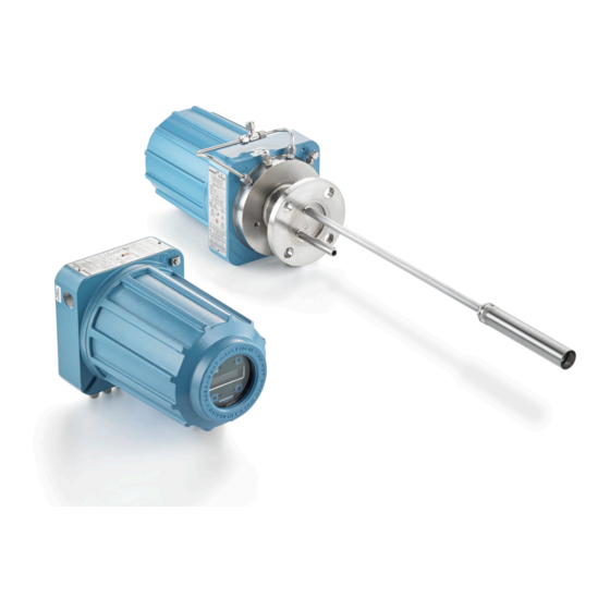
Oxygen and combustibles transmitter
Hide thumbs
Also See for Rosemount OCX8800:
- Instruction manual (306 pages) ,
- Reference manual (300 pages) ,
- Quick start manual (64 pages)

Related Manuals for Emerson Rosemount OCX8800


Summary of Contents for Emerson Rosemount OCX8800
- Page 1 Quick Start Guide 00825-0200-4880, Rev AD February 2020 ™ Rosemount OCX8800 Oxygen and Combustibles Transmitter ™ with F Fieldbus Protocol OUNDATION...
-
Page 2: Table Of Contents
February 2020 Essential instructions Emerson designs, manufactures, and tests its products to meet many national and international standards. Because these instruments are sophisticated technical products, you must properly install, use, and maintain them to ensure they continue to operate within their normal specifications. You must adhere to the following instructions and integrate them into your safety program when installing, using, and maintaining Emerson's Rosemount products. -
Page 3: Description And Specifications
Quick Start Guide Description and specifications Component checklist Check the model number of your Rosemount OCX8800 against the transmitter features and options, making sure options specified by this number are on or included with the unit. Use this complete model number for any correspondence with Emerson. -
Page 4: Installation
The sensor housing must not be mounted to any surface or flange that exceeds 383 °F (195 °C). The sample entering the sensor housing must not exceed 383 °F (195 °C). Rosemount OCX8800... - Page 5 February 2020 Quick Start Guide WARNING Electrical shock Failure to install covers and ground leads could result in serious injury or death. Install all protective equipment covers and ground leads after installation. If external loop power is used, the power supply must be a safety extra low voltage (SELV) type.
- Page 6 1. Ensure all components are available to install the Rosemount OCX8800. Refer to Figure 1-1 2. The Rosemount OCX8800 may be installed intact as it is received. 3. Weld or bolt adapter plate onto the duct. 4. Use the pipe or wall mounting hardware to mount a remote electronics housing.
- Page 7 Uninsulated stacks or ducts may cause ambient temperatures in the electronics housing to exceed 185 °F (85 °C) and damage the electronics. 8. If insulation is removed to access the duct for Rosemount OCX8800 mounting, make sure to replace insulation afterward. Quick Start Guide...
- Page 8 Quick Start Guide February 2020 Example Figure 2-1: Installation, Rosemount OCX8800 with Integral Electronics A. Alarm output relay terminal block ™ B. F fieldbus OUNDATION ® C. HART D. Signal output terminal block E. Ground stud F. Earth ground typical for electronics and sensor housing G.
- Page 9 February 2020 Quick Start Guide J. EMI filter K. External tooth lockswasher L. Signal port ¾ NPT M. Power port ¾ NPT Electrical installation All wiring must conform to local and national codes. Figure 2-2 shows factory wired solenoid power connections. WARNING Failure to install covers and ground leads could result in serious injury or death.
- Page 10 Fieldbus signal provides all output information and is OUNDATION accessible through a Handheld Communicator. 2.3.7 Alarm output relay Connect any customer-supplied relay input to the alarm output relay terminal. Use shielded wire and terminate the shield at the electronics Rosemount OCX8800...
- Page 11 February 2020 Quick Start Guide housing. The alarm output relay terminal is a set of dry, number 2, form C contacts with 30 mA, 30 Vdc capacity. 2.3.8 Remote electronics connections to sensor housing Make the following connections between the remote electronics and sensor housings with the electronics cable ordered with the package (Figure Braided cable is available in lengths up to 150 ft.
- Page 12 A. Alarm output relay terminal block ™ B. F Fieldbus OUNDATION ® C. HART D. Signal output terminal block E. Ground stud F. Earth ground typical for electronics and sensor housing G. Ground H. Customer wiring I. Terminal block J. EMI filter Rosemount OCX8800...
- Page 13 Failure to use proper gases will result in erroneous readings. Do not use 100 percent nitrogen as an O low gas. Emerson suggests using O low gas between 0.4 percent and 2.0 percent O Do not use gases with hydrocarbon concentrations of more than 40 parts per million.
- Page 14 Quick Start Guide February 2020 Figure 2-3: Pneumatic Installation, Rosemount OCX8800 with Reference Air Set without Autocalibration A. Sensor housing B. Eductor air in C. Electronics housing D. Calibration gas in E. Reference air in F. Dilution air in G. Dilution air flow meter 0.1 scfh H.
- Page 15 February 2020 Quick Start Guide M. 2-in. (50.8 mm) pressure gauge, 0 to 60 psig (0 to 413.7 kPa) N. Combination filter-regulator, 0 to 60 psig (0 to 413.7 kPa) O. Flow meter, 1-10 scfh P. Flow meter, 0.05-0.5 scfh 2.4.2 Reference air set and solenoids option without COe zero function When the reference air set and test gas solenoids are included with your...
- Page 16 Quick Start Guide February 2020 Figure 2-4: Pneumatic Installation, Rosemount OCX8800 with Reference Air Set, Solenoids, and Autocalibration, without COe Zero Function A. Sensor housing B. Eductor air in C. Electronics housing D. Calibration gas in E. Reference air in F.
- Page 17 February 2020 Quick Start Guide O. Flow meter 1-10 scfh P. Flow meter 0.05-0.5 scfh Q. Calibration gas out 2.4.3 Reference air set and solenoids option with COe zero function Figure 2-5 shows the piping arrangement for the transmitter with autocalibration when the COe Zero Function is used.
- Page 18 Quick Start Guide February 2020 Figure 2-5: Pneumatic Installation, Rosemount OCX8800 with Reference Air Set, Solenoids, and Autocalibration, with COe Zero Function A. Sensor housing B. Eductor air in C. Electronics housing D. Calibration gas in E. Reference air in F.
- Page 19 February 2020 Quick Start Guide O. Flow meter, 1-10 scfh P. Flow meter, 0.05-0.5 scfh Q. Calibration gas out Note If instrument is to be used as the high O calibration gas, the low O and COe calibration gases must also be set to the same pressure (e.g., 35 psig). 2.4.4 Reference air set, solenoids, and blowback option with COe zero function...
- Page 20 G. Instrument air H. Calibration gas flow meter (7 scfh, 20-30 psig recommended) I. Two-stage regulators J. Instrument air supply K. Pressure regulator/filter, 35 psig - general purpose L. Calibration gas out M. Check valve N. Actuating air Rosemount OCX8800...
- Page 21 February 2020 Quick Start Guide O. Normally open solenoid valve P. Normally closed solenoid valve Q. Blowback valve, air operated R. 2-in. (50.8 mm) pressure gauge, 0-60 psig S. Combination filter/regulator, 0-60 psig T. Flow metet, 1-10 scfh U. Flow meter, 0.05-0.5 scfh V.
- Page 22 8. Install an air line between the instrument air outlet fitting on the electronics housing and the control air inlet fitting on the air- operated solenoid valve. Rosemount OCX8800...
- Page 23 February 2020 Quick Start Guide Figure 2-7: Pneumatic Installation, Rosemount OCX8800 with Reference Air Set, Solenoids, Blowback, and Autocalibration without COe Zero Function A. Sensor housing B. Eductor air in C. Electronics housing D. Reference air in E. Dilution air in F.
- Page 24 2-6. Piping arrangement for blowback panel with autocalibration without COe Zero Function is shown in Figure 2-7. Piping arrangement for blowback panel with autocalibration with COe Zero Function is shown in Figure 2-8. During blowback operation, states of both solenoid valves change. Rosemount OCX8800...
- Page 25 February 2020 Quick Start Guide Figure 2-8: Pneumatic Installation, Blowback Panel without Autocalibration without COe Zero Function A. Sensor housing B. Eductor air in C. Electronics housing D. CAL gas in E. Reference air in F. Dilution air in G. Instrument air H.
- Page 26 Quick Start Guide February 2020 J. Dilution air out K. Blowback air out L. Blowback control air M. Instrument air supply N. Instrument air to electronics O. Two-stage regulators P. Actuating air Q. Check valve Rosemount OCX8800...
- Page 27 February 2020 Quick Start Guide Figure 2-9: Pneumatic Installation, Blowback Panel with Autocalibration without COe Zero Function A. Sensor housing B. Eductor air in C. Electronics housing D. CAL gas in E. Reference air in F. Dilution air in G. Instrument air H.
- Page 28 Quick Start Guide February 2020 J. Dilution air out K. Blowback air out L. Blowback control air M. Instrument air supply N. Instrument air to electronics O. Two-stage regulators P. Actuating air Q. Check valve Rosemount OCX8800...
- Page 29 February 2020 Quick Start Guide Figure 2-10: Pneumatic Installation, Blowback Panel with Autocalibration with COe Zero Function A. Sensor housing B. Eductor air in C. Electronics housing D. CAL gas in E. Reference air in F. Dilution air in G. Instrument air H.
- Page 30 Upon completing installation, make sure that the transmitter is turned on and operating prior to firing up the combustion process. During outages, and whenever possible, leave the transmitter running to prevent condensation and premature aging from thermal cycling. Rosemount OCX8800...
-
Page 31: Configuration And Startup
This switch is accessible through holes in the electronics box. CAUTION If defaults are changed under power, damage to the electronics may occur. Remove power from the Rosemount OCX8800 before changing defaults. Quick Start Guide... - Page 32 Quick Start Guide February 2020 Figure 3-1: Rosemount OCX8800 Defaults - Fieldbus Electronics A. Switch default positions shown Verify that the following switch settings are correct for your Rosemount OCX8800 installation: SW3 The factory sets this switch as follows: •...
- Page 33 5. Press Down several times to display COe Test Gas. Enter the CO concentration (ppm) used for COe test gas. Calibration solenoids Emerson can provide the transmitter with optional calibration solenoids for autocalibration. The transmitter's software controls the solenoids, which automatically switch in the proper calibration gas during the calibration cycle.
- Page 34 The blowback feature requires the optional blowback hardware to be properly installed external to the transmitter. A Rosemount OCX8800 shipped from the factory must be configured before blowback can be implemented. This same process must be performed any time a replacement card stack is installed.
- Page 35 Also set the following parameters: • Blow Bk Intrvl: Length of time between blowback events. Range is 0 to 32,000 minutes. Default is 60 minutes. Emerson recommeneds 60 minutes. • Blow Bk Period: Length of time blowback in activated. Range is one to five seconds.
- Page 36 The COe zero feature is only valid if the transmitter is supplied with calibration solenoids and the solenoids have been activated. A Rosemount OCX8800 shipped from the factory must be configured before the COe zero feature can be implemented. This same process must be performed any time a replacement card stack is installed.
- Page 37 February 2020 Quick Start Guide • COe Zero Update - Determines if the COe calibration constant is updated at the end of the function. Valid choices are Yes and No. A Yes choice will cause the COe calibration constant to update. 3.6.2 Configure COe zero with the LOI Procedure...
-
Page 38: Using The Local Operator Interface (Loi)
When you touch the Enter key, the new parameter value, if accepted, will appear in the top line of the display. Rosemount OCX8800... - Page 39 February 2020 Quick Start Guide Use the blue (bottom left) key as a selector when choosing from among several menu items. This right-pointing key also will move the cursor to the right when entering the digits of a new parameter value. Use the up and down pointing keys to increment up and down when selecting from a vertical list of menu items.
- Page 40 Quick Start Guide February 2020 Figure 4-2: Z Pattern Entry Rosemount OCX8800...
-
Page 41: Calibration
5.1.1 Set up autocalibration using the optional LOI Use the following procedure to set up the Rosemount OCX8800 for automatic calibration. Note Automatic calibration is only available on units equipped with calibration solenoids. - Page 42 5.1.2 Set up autocalibration using the Field Communicator - Fieldbus Use the following procedure to specify a time interval (in hours) at which the Rosemount OCX8800 will automatically calibrate. Note Automatic calibration is only available on units equipped with calibration solenoids.
- Page 43 February 2020 Quick Start Guide 5.2.2 Autocalibrate using the Field Communicator - Fieldbus To initiate an automatic calibration using the Field Communicator, perform the following steps: Procedure 1. From the Transducer screen, select Methods. 2. Select OCX Calibration from the Methods menu. 3.
- Page 44 OK. 7. Set the Select Action screen to the following values/settings. From the Select Action screen, select Update Display to refresh the calibration status, select Next Calibration Step to continue calibration, select Rosemount OCX8800...
- Page 45 February 2020 Quick Start Guide Abort Calibration to abort calibration, or select Exit to exit calibration. Select one item from the list and press OK. The Select Action screen is static and data will not be automatically refreshed. • Calibration Step: Idle •...
- Page 46 When the Purge step is complete, the Calibration Step will be at . The alarm will be set if the Idle Calibration Failed calibration has failed. 17. When calibration is complete, select Exit to exit the calibration method. Rosemount OCX8800...
-
Page 47: Product Certifications
A copy of the EU Declaration of Conformity can be found at the end of the Quick Start Guide. The most recent revision of the EU Declaration of Conformity can be found at Emerson.com/Rosemount. Ordinary location certification As standard, the transmitter has been examined and tested to determine... - Page 48 2. The pressure within the enclosure and gas lines shall not be higher than 1.1 times the atmospheric pressure during the normal operation of the equipment. 3. Flameproof joints are not intended to repaired. Rosemount OCX8800 Oxygen/Combustibles Transmitter (OCX88C) for Hazardous Locations 6.5.1 Certificate: 1602514 Standards: C22.2 No.
- Page 49 February 2020 Quick Start Guide UL 50 (Tenth Edition) Markings: Class 1, Zone 1, AEx db IIB+H T* Gb Ex db IIB+H T* Gb Type 4X, IP66** *Sensor assembly enclosure: T3 (-40 °C <= Tamb <= +100 °C) *Electronics assembly enclosure: T6 (-40 °C <= Tamb <= +65 °C) *Integral configuration: T3 (-40 °C <= Tamb <= +65 °C) **when reference air vents are routed to a dry area...
- Page 50 2. The pressure within the enclosure and gas lines shall not be higher than 1.1 times atmospheric pressure during normal operation. 3. Flameproof joints are not intended to be repaired. 4. Precautions shall be taken to minimize the risk from electrostatic discharge of painted parts. Rosemount OCX8800...
- Page 51 February 2020 Quick Start Guide 6.5.4 International IECEx Certificate: IECEx CSA 10.0002X Standards: IEC 60079-0: 2017 Edition 7.0 IEC 60079-1: 2014-06 Edition 7.0 Markings: Transmitter: Ex db IIB+H T6 Gb; Tamb: -40 °C to 65 °C Sensor: Ex db IIB+H T3 Gb;...
-
Page 52: Declaration Of Conformity
Quick Start Guide February 2020 Declaration of Conformity Rosemount OCX8800... - Page 53 February 2020 Quick Start Guide Quick Start Guide...
- Page 54 Quick Start Guide February 2020 Rosemount OCX8800...
-
Page 55: China Rohs Table
February 2020 Quick Start Guide China RoHS table Quick Start Guide... - Page 56 Quick Start Guide February 2020 Rosemount OCX8800...
- Page 57 February 2020 Quick Start Guide Quick Start Guide...
- Page 58 Quick Start Guide February 2020 Rosemount OCX8800...
- Page 59 February 2020 Quick Start Guide Quick Start Guide...
- Page 60 Linkedin.com/company/Emerson- Automation-Solutions The Emerson logo is a trademark and service mark of Emerson Electric Co. Rosemount is a twitter.com/rosemount_news mark of one of the Emerson family of companies. Facebook.com/Rosemount All other marks are the property of their youtube.com/RosemountMeasurement respective owners.
Need help?
Do you have a question about the Rosemount OCX8800 and is the answer not in the manual?
Questions and answers