Sign In
Upload
Manuals
Brands
Emerson Manuals
Transmitter
Rosemount OCX 8800
Emerson Rosemount OCX 8800 Manuals
Manuals and User Guides for Emerson Rosemount OCX 8800. We have
7
Emerson Rosemount OCX 8800 manuals available for free PDF download: Instruction Manual, Reference Manual, Quick Start Manual
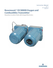
Emerson Rosemount OCX 8800 Instruction Manual (306 pages)
Oxygen and Combustibles Transmitter, Hazardous Location Probe with Integral Electronics
Brand:
Emerson
| Category:
Transmitter
| Size: 5.89 MB
Table of Contents
Table of Contents
11
Section 1:Description and Specifications
25
Section Contents
25
Component Checklist
25
System Overview
26
Scope
26
Figure 1-1 Typical System Package
26
System Description
27
System Configuration
28
System Features
29
System Operation
30
Figure 1-2 System Operation Diagram
30
Handling the Hazardous Area OCX 8800
31
System Considerations
31
Figure 1-3 Communication Connections and Afigure 1-3 AMS Application - Hazardous Area OCX 8800 with Integral Electronics
32
Figure 1-4 Typical System Installation - Integral Electronics
32
Figure 1-5 Typical System Installation - Remote Electronics
33
Figure 1-6 Optional Sample Tube Support
34
Figure 1-7. Optional In-Situ Filters
35
Figure 1-8. Optional Panel Mounted Blowback and Calibration/Reference Air Set
35
Specifications
36
Product Matrix - Hazardous Area OCX 8800
38
Table 1-1 Product Matrix - Hazardous Area OCX 8800
38
Table 1-2 Accessories
39
Section 2: Installation
40
Section Contents
40
Product Safety
40
Mechanical Installation
42
Selecting a Location
42
Installation
42
Figure 2-2 Installation, Hazardous Area OCX 8800 with Integral Electronics
43
Figure 2-3 Installation, Hazardous Area OCX 8800 with Remote Electronics
44
Figure 2-4 Adapter Plate Installation
45
Figure 2-5 Wall or Pipe Mounting of Electronics Housing
46
Figure 2-6 Installation with Drip Loops
47
Electrical Installation
48
Electrical Connections
49
Connect Line Voltage
49
Connect Output Signals
49
O2 4-20 Ma Signal
50
Coe 4-20 Ma Signal
50
Foundation Fieldbus Signal
50
Alarm Output Relay
50
Remote Electronics Connections to Sensor Housing
50
Signal Connections
50
Heater Power Connections
50
Figure 2-7 Line Voltage, Earth, and 4-20 Ma Connections
51
Figure 2-9 Customer-Furnished Interconnect Wiring or Cables
53
Pneumatic Installation
54
Reference Air Set Option (Only)
54
Figure 2-10 Pneumatic Installation, OCX with Reference Air Set Without Autocalibration
55
Figure 2-11 Pneumatic Installation, OCX with Reference Air Set, Solenoids and Autocalibration
56
Reference Air Set and Solenoids Option Without Coe Zero Function
57
Reference Air Set and Solenoids Option with Coe Zero Function
58
Figure 2-12 Pneumatic Installation, OCX with Reference Air Set, Solenoids and Autocalibration, with
58
Reference Air Set, Solenoids, and Blowback Option with Coe Zero Function
59
Coe Zero Function35
59
Reference Air Set, Solenoids, and Blowback Option Without
59
Figure 2-13 Pneumatic Installation, OCX with Reference Air Set, Solenoids, Blowback and
60
Reference Air Set and Blowback Panels
62
Figure 2-15 Pneumatic Installation, Blowback Panel Without Autocalibration Without Coe Zero Function
63
Figure 2-16 Pneumatic Installation, Blowback Panel with Autocalibration Without Coe Zero Function
64
Figure 2-17 Pneumatic Installation, Blowback Panel with Autocalibration with Coe Zero Function
65
Initial Startup
66
Section 3: Configuration and Startup
67
Section Contents
67
Verify Installation
67
Verify Configuration - HART Electronics
67
Figure 3-1 Hazardous Area OCX 8800 Defaults - HART Electronics
69
Verify Configuration - Fieldbus Electronics
70
Figure 3-2 Hazardous Area OCX 8800 Defaults - Fieldbus Electronics
70
Initial Power up
71
Set Test Gas Values
71
Setting Test Gas Values with the Field Communicator
71
Setting Test Gas Values with Fieldbus Communicator
71
Setting Test Gas Values with the LOI
72
Calibration Solenoids
72
Configuring the Calibration Solenoids with the Field Communicator - HART
72
Configuring the Calibration Solenoids with the Field Communicator - Fieldbus
72
Configuring the Calibration Solenoids with the LOI
73
Blowback Feature
73
Configuring Blowback with the Field Communicator - HART
73
Use the 375 Field Communicator or AMS Software
73
Configuring Blowback with the LOI
74
Calibration Verify Feature
74
Performing a Calibration Verify with the Field Communicator - HART
75
Performing a Calibration Verify with the Field Communicator - Fieldbus
75
Performing a Calibration Verify with the LOI
76
Calibration Tolerance Feature
77
Configuring the Calibration Tolerance Feature with the Field
77
Communicator - HART
77
Communicator - Fieldbus
77
Configuring the Calibration Tolerance Feature with the LOI
77
Coe Purge/ Zero Feature
78
Configuring the Coe Zero Feature with the Field
79
Communicator - HART
79
Configuring the Calibration Tolerance Feature with the Field Communicator - Fieldbus
79
Configuring the Coe Zero Feature with the LOI
80
OCX 8800 Reset Procedure
80
OCX Reset with the LOI
81
OCX Reset with the Field Communicator
81
Section 4: Using the LOI
82
Section Contents
82
Overview
82
Display Orientation
82
Figure 4-2. LOI Components Mounting
82
LOI Controls
83
Overview
83
LOI Assembly
83
LOI Key Functions
83
Figure 4-3 LOI Assembly
83
Lockout
84
Figure 4-4 'Z' Pattern Entry
84
LOI Status Codes
85
LOI Menu Tree
85
First Column Submenus
85
Second Column Submenus
85
Table 4-1. LOI Status Codes
85
Third and Fourth Column Submenus
86
Figure 4-5 LOI Menu Tree (Sheet 1 of 4)
86
Figure 4-6 LOI Menu Tree (Sheet 2 of 4)
87
Figure 4-7 LOI Menu Tree (Sheet 3 of 4)
88
Figure 4-8 LOI Menu Tree (Sheet 4 of 4)
89
Section 5: Calibration
90
Section Contents
90
Overview
90
Fully Automatic Calibration
90
Autocalibration Setup Using HART
90
Operator - Initiated Autocalibration
91
Autocalibration Using HART
91
Manual Calibration
92
Manual Calibration Using the Optional LOI
92
Manual O2 Calibration Using the Field Communicator - HART
93
Manual Coe Calibration Using the Field Communicator - HART
94
Manual O2 and Coe Calibration Using the Field Communicator - HART
96
Manual O2/Coe Calibration Using the Field Communicator - Fieldbus
98
D/A Trim Procedures - LOI
100
O2 D/A Trim Procedure Using the LOI
100
Coe D/A Trim Procedure Using the LOI
101
D/A Trim Procedures - HART
102
O2 D/A Trim Procedure Using HART
102
Coe D/A Trim Procedure Using HART
103
Section 6: Field Communicator
104
Section Contents
104
Overview
104
Field Communicator Connections
104
Connecting to a HART Loop
104
Connecting to a Fieldbus Segment
105
Figure 6-2 375 Communicator Connections - HART
105
Off-Line and On-Line Operations
106
Figure 6-3 375 Communicator Connections - Fieldbus
106
Hart Menu Tree
107
Figure 6-4 HART Menu Tree (Sheet 1 of 4)
107
Figure 6-5 HART Menu Tree (Sheet 2 of 4)
108
Figure 6-6 HART Menu Tree (Sheet 3 of 4)
109
Figure 6-7 HART Menu Tree (Sheet 4 of 4)
110
Fieldbus Menu Tree
111
Figure 6-8 Fieldbus Menu Tree (Sheet 1 of 3)
111
Figure 6-9 Fieldbus Menu Tree (Sheet 2 of 3)
112
Figure 6-10 Fieldbus Menu Tree (Sheet 3 of 3)
113
Section 7: Foundation Fieldbus
114
Section Contents
114
Foundation Fieldbus Technology
114
Overview
114
Introduction
116
Function Blocks
116
Device Descriptions
117
Figure 7-2 Function Block Internal Structure
117
Instrument-Specific Function Blocks
118
Resource Blocks
118
Transducer Blocks
118
Alerts
118
Network Communication
119
Link Active Scheduler (LAS)
119
Figure 7-3 Single Link Fieldbus Network
119
Device Addressing
120
OCX Function Blocks
120
Implemented Function Blocks
120
Table 7-1 OCX Implemented Function Blocks
120
Resource Block
121
Plantweb Alerts
121
Table 7-2 Hazardous Area OCX 8800 PWA
121
Mapping of PWA
122
Table 7-3 Description of Plantweb Alerts
122
PWA Simulate
125
Fieldbus/Pwa Simulate
126
Configure Simulation from AMS
126
Figure 7-4 Simulate PWA Screen
127
Configure Simulation with the Model 375 Field Communicator
128
Support Resource Block Errors
129
Transducer Block
129
Transducer Block Parameters
129
Table 7-4 Transducer Block Parameter Description
130
Transducer Block Enumerations
134
Calibration States
134
Calibration Step Command
134
Table 7-5 Calibration State- Values
134
Table 7-6 Calibration Control Enumerations
134
Table 7-7 Blowback State Enumerations
135
Table 7-8 Alarm Event Enumerations
135
Table 7-9 Operating Mode Enumerations
135
Table 7-10 Sensor Housing Enumerations
136
Table 7-11 Cal Results Bit Enumerations
136
Table 7-12 Calibration Verify State Values
136
Table 7-13 Calibration Verify Step Values
136
Table 7-14 Coe Zero State Enumerations
137
Table 7-15 Coe out Tracks Enumerations
137
Table 7-16 Detailed Status
137
Transducer Block Channel Assignments for AI Blocks
138
Table 7-17 I/O Channel Assignments
138
Table 7-18 Recommended Settings for the I/O Channel Assignments for the AI Blocks
138
Transducer Block Channel Status
139
Table 7-19 I/O Channel Status
139
Transducer Block Simulate
140
Support Transducer Block Errors
140
Analog Input (AI) Function Block
140
Introduction
140
Figure 7-5 AI Function Block
140
Table 7-20 Definitions of Analog Input Function Block System Parameters
141
Simulation
143
Figure 7-6 Analog Input Function Block Schematic
143
Filtering
144
Signal Conversion
144
Direct Signal Conversion
144
Figure 7-7 Analog Input Function Block Timing Diagram
144
Indirect Signal Conversion
145
Indirect Square Root
145
Block Errors
146
Modes
146
Table 7-21 BLOCK_ERR Conditions
146
Alarm Detection
147
Status Handling
148
Advanced Features
148
Application Information
149
Application Examples
149
Table 7-22 Analog Input Function Block Configuration for a Typical Temperature Transmitter
149
Pressure Transmitter Used to Measure Level in an Open Tank
150
Figure 7-8 Analog Input Function Block Configuration for a Typical Temperature Transmitter
150
Figure 7-9 Situation #1 Diagram
150
Table 7-23 Analog Input Function Diagram for a Pressure Transmitter Used in Level Measurement (Situation #1)
151
Figure 7-10 Function Block Diagram for a Pressure Transmitter Used in Level Measurement
151
Table 7-24 Analog Input Function Diagram for a Pressure Transmitter Used in
152
Figure 7-11 Situation #2 Diagram
152
Differential Pressure Transmitter to Measure Flow
153
Table 7-25 Analog Input Function Block Configuration for a Differential Pressure Measurement
153
Figure 7-12 Function Block Diagram for a Differential Pressure Transmitter Used in a
153
Troubleshooting
154
Table 7-26 Troubleshooting
154
Proportional/ Integral/Derivative (PID) Function Block
155
Figure 7-13 Proportional/ Integral/Derivative (PID) Function Block
155
Figure 7-14 PID Equation: Standard and Series
155
Table 7-27 PID Function Block System Parameters
156
Figure 7-15 PID Function Block Schematic
160
Figure 7-16 PID Function Block Setpoint Selection
161
Setpoint Selection and Limiting
161
Figure 7-17 PID Equation Structure
163
PID Equation Structures
163
Reset Limiting
163
Reverse and Direct Action
163
Block Errors
164
Modes
164
Table 7-28 BLOCK _ERR Conditions
164
Alarm Detection
165
Table 7-29 Alarm Priority Levels
165
Application Information
166
Status Handling
166
Application Examples
168
Figure 7-18 PID Function Block Steam Heater Control
168
Figure 7-19 PID Function Block Diagram for Steam Heater Control Example
169
Figure 7-20 PID Function Block Feedforward Control Example
169
Cascade Control with Master and Slave Loops
170
Figure 7-21 PID Function Block Diagram for Feedfoward Control
170
Figure 7-22 PID Function Block Cascade Control Example
171
Cascade Control with Override
172
Figure 7-23 PID Function Block Diagram for Cascade Control Example
172
Figure 7-24 Function Block Diagram for Cascade Control with Override
173
Table 7-30 Troubleshooting
174
Troubleshooting
174
Figure 7-25 Arithmetic (ARTHM) Function Block
175
Table 7-31 Arithmetic (ARTHM) Block
176
Block149 Errors
178
Figure 7-26 Arithmetic Function Block Diagram
178
Table 7-32 BLOCK_ERR Parameters
178
Alarm Detection
179
Block Execution
179
Modes
179
Table 7-33 Alarm Level Priorities
179
Application Information
180
Compensation Input Calculations
180
Figure 7-27 Relative Temperature Effects on Level
181
Figure 7-28 Arithmetric Function Block Diagram Example
181
Arithmetric Types
182
Table 7-34 Troubleshooting
183
Troubleshooting
183
Input Selector (ISEL) Function Block
184
Table 7-35 Input Selector Function Block System Parameters
184
Block Errors
186
Figure 7-30 Input Selector Function Block Schematic
186
Table 7-36 Block Error Conditions
186
Alarm Detection
187
Block Execution
187
Modes
187
Table 7-37 Alarm Priorities
187
Application Information
188
Figure 7-31 Input Selector Function Block Application Example (SEL_TYPE = Max)
188
Status Handling
188
Figure 7-32 Input Selector Function Block Application Example (SEL_TYPE = Avg.)
189
Figure 7-33 Input Selector Function Block Application Example (SEL_TYPE = Hot Backup)
189
Table 7-38 Input Selector Function Blocks
189
Operation with Emerson Deltav
190
About AMS and Deltav Software
190
Table 7-39 Troubleshooting ISEL Block
190
Figure 7-34 Deltav Explorer
191
Troubleshooting
190
Section 8: Troubleshooting
193
Section Contents
193
Overview
193
Grounding
193
Electrical Noise
193
Electrostatic Discharge
193
Total Power Loss
193
Diagnostic Alarms
195
Figure 8-3 Fuse Locations
195
Fault Isolation
196
Table 8-1 Troubleshooting
196
Figure 8-4. Oxygen and Cell Output
200
Figure 8-5 Electrical Connections between Electronics and Sensor Housing
203
Alarm Relay Events
204
Table 8-2 Alarm Relay Event Groups
204
Section 9:Maintenance and Service
206
Section Contents
206
Overview
206
OCX 8800 Removal and Installation
207
OCX with Integral Electronics
207
Figure 9-1 OCX with Integral Electronics
207
Figure 9-2 Electronics Housing Terminal Blocks
209
Install Hazardous Area OCX 8800
210
OCX with Remote Electronics
210
Figure 9-3 OCX with Remote Electronics
211
Install Sensor Housing
212
Figure 9-4 Sensor Housing Terminals
212
Remove Remote Electronics Housing
213
Figure 9-5 Electronics Housing Terminal Blocks
214
Install Remote Electronics Housing
215
Figure 9-6 Remote Electronics Housing Cable Connections
215
Repair Sensor Housing
216
Sensor Housing Disassembly
216
Figure 9-7 Removal of O2 Cell and Heater Strut Assembly
217
Remove O2 Cell and Heater Strut Assembly
218
Remove Sample Block Heater Rods
218
Remove Coe Sensor Assembly
219
Figure 9-8 O2 Cell, Thermocouple, and Heater Connections
219
Figure 9-9 Coe Sensor, Thermocouple, and Heater Connections
220
Figure 9-10 Removal of Coe Sensor Assembly
221
Figure 9-11 Alignment of Coe Sensor Assembly
222
Remove Eductor
223
Figure 9-12 Eductor Alignment Matchmarks
223
Figure 9-13 Removal of Sample and Exhaust Tubes
225
Figure 9-14 O2 Cell, Heater, and Thermocouple, Exploded View
227
Disassemble Coe Sensor Assembly
229
Figure 9-15 Coe Sensor, Exploded View
229
Sensor Housing Assembly
230
Figure 9-16 Coe Sensor and Pre-Heater Alignment
231
Assemble O2 Sensor and Heater Strut Assembly
232
Install Sample and Exhaust Tubes
232
Install Eductor
233
Figure 9-17 Installation of Eductor and Coe Sensor
233
Figure 9-18 Eductor Alignment Matchmarks
234
Install Coe Sensor Assembly
235
Figure 9-19 Band Heater Height
235
Figure 9-20 Coe Sensor Holder Alignment
236
Figure 9-21 Coe Sensor, Thermocouple, and Heater Connections
237
Figure 9-22 Installation of O2 Cell and Heater Strut Assembly
238
Install Sample Block Heater Rods
239
Install O2 Cell and Heater Strut Assembly
240
Install Terminals Insulator and Cover
240
Sensor Housing Leak Test
241
Repair Electronics Housing
241
Electronics Housing Disassembly
242
Remove Electronics Stack
243
Figure 9-24 Removal/Installation of Electronics Housing Components
243
Remove Solenoid Valves
244
Remove EMI Filter and Terminal Block
244
Figure 9-25 Removal/Installation of EMI Filter
244
Electronics Housing Assembly
245
Install EMI Filter and Terminal Block
245
Install Solenoid Valves
245
Install Electronics Stack
245
Install LOI Module and Board
245
Figure 9-26 Electronics Housing Cable Connections
246
Install Cover
247
Figure 9-27 Solenoid Power Terminals
247
Replace Tube Fittings
248
Remove Tube Fittings
249
Install Tube Fittings
250
Figure 9-28 Removal of Tube Fittings
250
Section 10:Replacement Parts
252
Section Contents
252
Sensor Housing
252
Figure 10-2 Sensor Housing Components (Sheet 1 of 2)
252
Table 10-1 Sensor Housing Components (Sheet 1)
253
Figure 10-3 Sensor Housing Components (Sheet 2 of 2)
254
Electronics Housing
256
Figure 10-4 Electronics Housing Components
256
Table 10-3 Electronics Housing Parts
257
Table 10-4 EMI Filter and Terminal Block Parts
257
Figure 10-5 EMI Filter and Terminal Block
257
Table 10-5 O2 Cell and Heater Strut Assembly
258
Figure 10-6 O2 Cell and Heater Strut Assembly
258
Appendix A: Safety Data
260
Appendix Contents
260
Safety Instructions
263
Safety Data Sheet for Ceramic Fiber Products
283
High Pressure Gas Cylinders
288
General Precautions for Handling and Storing High Pressure Gas Cylinders
288
ATEX Clarification
289
ATEX Compliant Gas Analysis Performed Within a Flameproof Enclosure
289
Appendix B: SPA with HART Alarm
291
Appendix Contents
291
Overview
291
Figure B-1 SPA with HART Alarm
291
Installation
292
Setup
292
Figure B-2 OCX 8800 and SPA Interface Connections
292
Figure B-3 SPA Jumper and Dip Switch Settings
293
Jumper and Switch Settings
293
Configuration/Calibration
294
Figure B-4 SPA Setup for Calibration
294
Figure B-5 SPA Front Panel
296
Figure B-6 SPA Configuration Menu for Hazardous Area OCX 8800 Communication
297
Appendix C: Returning Material
299
Returning Material
299
Appendix D: Index
300
Manual Index
300
Advertisement
Emerson Rosemount OCX 8800 Reference Manual (300 pages)
Oxygen and Combustibles Transmitter
Brand:
Emerson
| Category:
Transmitter
| Size: 18.17 MB
Table of Contents
Table of Contents
5
Chapter 1 Description and Specifications
11
Component Checklist
11
System Overview
13
Scope
13
System Description
13
System Configurations
14
System Features
15
System Operation
15
Handling the OCX 8800
16
System Considerations
16
Specifications
21
Net O Range
21
Combustibles
21
Accuracy
21
System Response to Test Gas
21
Temperature Limits
21
Nominal and Approximate Shipping Weights
22
Mounting
22
Materials
22
Calibration
23
Calibration Gas Mixtures Recommended (Ref. Test Gas Bottles Kit #1A9919G04)
23
Calibration Gas Flow
23
Reference Air
23
Eductor Air
23
Dilution Air
23
Blowback Air (Optional)
23
Certifications
24
Electrical Noise
24
Line Voltage
24
Pollution Degree
24
Over Voltage Category
24
Relative Humidity
25
Isolated Output
25
Alarm
25
Power Consumption
25
Product Matrix - OCX 8800
25
Chapter 2 Install
29
Product Safety
29
Mechanical Installation
30
Selecting a Location
30
Installation
31
Electrical Installation
36
Electrical Connections
39
Connect Line Voltage
39
Connect Output Signals
39
4-20 Ma Signal
39
Coe 4-20 Ma Signal
39
Foundation Fieldbus Signal
39
Alarm Output Relay
39
Remote Electronics Connections to Sensor Housing
40
Signal Connections
42
Heater Power Connections
42
Pneumatic Installation
42
Reference Air Set Option (Only)
42
Reference Air Set and Solenoids Option Without Coe Zero Function
44
Reference Air Set and Solenoids Option with Coe Zero Function
46
Reference Air Set, Solenoids, and Blowback Option with Coe Zero Function
48
Initial Startup
52
Chapter 3 Configuration and Startup
53
Verify Installation
53
Verify Configuration - HART Electronics
53
Verify Configuration - Fieldbus Electronics
55
Initial Power up
56
Set Test Gas Values
56
Setting Test Gas Values with the Field Communicator
56
Setting Test Gas Values with Fieldbus Communicator
56
Setting Test Gas Values with the LOI
57
Calibration Solenoids
57
Configuring the Calibration Solenoids with the Field Communicator - HART
57
Configuring the Calibration Solenoids with the Field Communicator - Fieldbus
58
Configuring the Calibration Solenoids with the LOI
58
Blowback Feature
58
Configuring Blowback with the Field Communicator - HART
58
Configuring Blowback with the Field Communicator - Fieldbus
59
Configuring Blowback with the LOI
59
Calibration Verify Feature
60
Performing a Calibration Verify with the Field Communicator - HART
60
Performing a Calibration Verify with the Field Communicator - Fieldbus
61
Performing a Calibration Verify with the LOI
61
Calibration Tolerance Feature
62
Configuring the Calibration Tolerance Feature with the Field Communicator -HART
62
Configuring the Calibration Tolerance Feature with the Field Communicator - Fieldbus
62
Configuring the Calibration Tolerance Feature with the LOI
63
Coe Purge / Zero Feature
63
Configuring the Coe Zero Feature with the Field Communicator - HART
64
Configuring the Coe Zero Feature with the Field Communicator - Fieldbus
64
Configuring the Coe Zero Feature with the LOI
65
Reset Procedure
65
Reset with the LOI
66
Reset with Field Communicator
66
Chapter 4 Using the LOI
67
Display Orientation
67
LOI Controls
68
Overview
68
LOI Key Functions
69
Lockout
70
LOI Status Codes
72
LOI Menu Tree
72
First Column Submenus
76
Second Column Submenus
76
Third and Fourth Column Submenus
77
Chapter 5 Calibration
79
Overview
79
Fully Automatic Calibration
79
Autocalibration Setup Using HART
79
Operator-Initiated Autocalibration
80
Autocalibration Using HART
80
Manual Calibration
80
Manual Calibration Using the Optional LOI
81
Manual O Calibration Using the Field Communicator - HART
82
Manual Coe Calibration Using the Field Communicator - HART
83
Manual O and Coe Calibration Using the Field Communicator - Fieldbus
85
D/A Trim Procedures - LOI
87
O 2 D/A Trim Procedure Using the LOI
87
Coe D/A Trim Procedure Using the LOI
88
D/A Trim Procedures - HART
89
O 2 D/A Trim Procedure Using HART
89
Coe D/A Trim Procedure Using HART
91
Chapter 6 Field Communicator
93
Overview
93
Field Communicator Connections
93
Connecting to a HART Loop
93
Connecting to a Fieldbus Segment
94
HART Menu Tree
96
Fieldbus Menu Tree
100
Chapter 7 Foundation Fieldbus
105
Foundation Fieldbus Technology
105
Overview
105
Introduction
105
Function Blocks
106
Device Descriptions
107
Instrument-Specific Function Blocks
107
Network Communication
108
Link Active Scheduler (LAS)
109
Device Addressing
109
OCX Function Blocks
110
Implemented Function Blocks
110
Resource Block
110
Plantweb Alerts
110
Mapping of PWA
111
Pwa Simulate
120
Fieldbus/Pwa Simulate
121
Configure Simulation from AMS
121
Configure Simulation with the Model 375 Field Communicator
122
Support Resource Block Errors
123
Transducer Block
123
Transducer Block Parameters
124
Transducer Block Enumerations
132
Calibration States
132
Calibration Step Command
133
Transducer Block Channel Assignments for AI Blocks
138
Transducer Block Channel Status
138
Transducer Block Simulate
139
Support Transducer Block Errors
139
Analog Input (AI) Function Block
140
Introduction
140
Simulation
145
Filtering
148
Signal Conversion
148
Direct Signal Conversion
148
Indirect Signal Conversion
149
Indirect Square Root
149
Block Errors
149
Modes
150
Alarm Detection
150
Status Handling
151
Advanced Features
152
Application Information
152
Application Examples
153
Pressure Transmitter Used to Measure Level in an Open Tank
153
Differential Pressure Transmitter to Measure Flow
157
Troubleshooting
157
Proportional/Integral/Derivative (PID) Function Block
159
Setpoint Selection and Limiting
168
PID Equation Structures
170
Reverse and Direct Action
171
Reset Limiting
171
Block Errors
171
Modes
172
Alarm Detection
172
Status Handling
173
Application Information
174
Application Examples
175
Cascade Control with Master and Slave Loops
177
Cascade Control with Override
179
Troubleshooting
180
Airthmetic (ARTHM) Function Block
182
Block Errors
185
Modes
186
Alarm Detection
186
Block Execution
187
Compensation Input Calculations
187
Application Information
188
Advanced Topics
189
Arithmetic Types
189
Troubleshooting
190
Input Selector (ISEL) Function Block
191
Block Errors
195
Modes
195
Alarm Detection
196
Block Execution
196
Status Handling
197
Application Information
197
Troubleshooting
199
Operation with Emerson Deltav
199
About AMS and Deltav Software
199
Chapter 8 Troubleshooting
203
Overview
203
Grounding
203
Electrical Noise
203
Electrostatic Discharge
203
Total Power Loss
204
Diagnostic Alarms
206
Fault Isolation
206
Alarm Relay Events
215
Chapter 9 Maintenance and Service
219
Overview
219
Removal and Installation
219
OCX with Integral Electronics
219
OCX with Remote Electronics
223
Repair Sensor Housing
226
Sensor Housing Assembly
243
Repair Electronics Housing
258
Electronics Housing Disassembly
258
Electronics Housing Assembly
262
Chapter 10 Replacement Parts
265
Sensor Housing
265
Electronics Housing
269
Cell and Heater Strut Assembly
272
Appendix A Safety Data
275
Safety Instructions
275
Safety Data Sheet for Ceramic Fiber Products
276
Identification
276
Physical Data
276
Hazardous Ingredients
277
Fire and Explosion Data
277
Health Hazard Data
277
Reactivity Data
279
Spill or Leak Procedures
279
Special Precautions
279
High Pressure Gas Cylinders
281
General Precautions for Handling and Storing High Pressure Gas Cylinders
281
ATEX Clarification
282
ATEX Compliant Gas Analysis Performed Within a Flameproof Enclosure
282
Appendix Bspa with HART Alarm
285
Overview
285
Description
285
Installation
287
Setup
287
Jumper and Switch Settings
288
Configuration/Calibration
289
Appendix C Returning Material
295
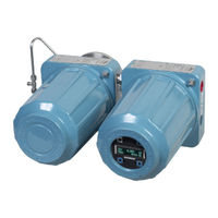
Emerson Rosemount OCX 8800 Instruction Manual (168 pages)
Oxygen/Combustibles Transmitter
Brand:
Emerson
| Category:
Transmitter
| Size: 4.4 MB
Table of Contents
Table of Contents
5
Essential Instructions
7
Preface
8
Definitions
8
Symbols
8
Component Checklist
9
System Overview
9
Sensor Housing
13
System Considerations
14
Specifications
17
Installation
21
Electrical Installation
27
Pneumatic Installation
30
Initial Startup
36
Verify Installation
37
Initial Power up
39
Set Test Gas Values
40
OCX 8800 Reset Procedure
40
Overview
41
Display Orientation
41
LOI Controls
42
Overview
42
LOI Key Functions
42
LOI Status Codes
43
LOI Menu Tree
44
D/A Trim Procedures
48
Overview
51
HART Communicator Signal Connections
51
HART Communicator PC Connections
54
HART Menu Tree
55
D/A Trim Procedures
59
Overview
61
Fully Automatic Calibration
61
Operator - Initiated Autocalibration
64
Manual Calibration
64
Overview
71
OCX 8800 Removal
71
And Installation
71
OCX with
72
Integral Electronics
72
Repair Sensor Housing
75
Sensor Housing Disassembly
75
Sensor Housing Assembly
85
Repair Electronics Housing
95
Electronics Housing Disassembly
95
Electronics Housing Assembly
98
Replace Tube Fittings
101
Remove Tube Fittings
101
Install Tube Fittings
102
Overview
103
Grounding
103
Electrical Noise
103
Electrostatic Discharge
103
Total Power Loss
104
Diagnostic Alarms
104
Fault Isolation
105
Alarm Relay Events
113
Sensor Housing
116
Electronics Housing
120
O2 Cell and Heater Strut Assembly
123
Safety Instructions
126
Appendix A
148
Safety Data Sheet for Ceramic Fiber Products
148
High Pressure Gas Cylinders
153
Atex Clarification
155
Appendix B
157
Overview
157
Description
157
Installation
158
Setup
158
Returning Material
163
Advertisement
Emerson Rosemount OCX 8800 Quick Start Manual (64 pages)
Oxygen and Combustibles Transmitter with 4–20 mA HART Protocol
Brand:
Emerson
| Category:
Transmitter
| Size: 5.35 MB
Table of Contents
Table of Contents
2
Description and Specifications
3
Installation
5
Configuration and Startup
33
Using the LOI
41
Calibration
44
Product Certifications
53
Declaration of Conformity
58
Emerson Rosemount OCX 8800 Quick Start Manual (60 pages)
Oxygen and Combustibles Transmitter
Brand:
Emerson
| Category:
Transmitter
| Size: 4.79 MB
Table of Contents
Table of Contents
2
Description and Specifications
3
Installation
4
Configuration and Startup
31
Using the Local Operator Interface (LOI)
38
Calibration
41
Product Certifications
47
Declaration of Conformity
52
China Rohs Table
55
Emerson Rosemount OCX 8800 Quick Start Manual (56 pages)
Oxygen and Combustibles Transmitter with 4–20 mA HART Protocol
Brand:
Emerson
| Category:
Transmitter
| Size: 3.95 MB
Table of Contents
Table of Contents
3
Installation
6
Configuration and Startup
30
Using the Local Operator Interface (LOI)
38
Calibration
41
Product Certifications
49
Declaration of Conformity
53
China Rohs Table
55
Emerson Rosemount OCX 8800 Quick Start Manual (56 pages)
Oxygen and Combustibles Transmitter with FOUNDATION Fieldbus Protocol
Brand:
Emerson
| Category:
Transmitter
| Size: 3.95 MB
Table of Contents
Table of Contents
3
Configuration and Startup
30
Using the Local Operator Interface (LOI)
37
Calibration
40
Product Certifications
46
Declaration of Conformity
50
China Rohs Table
52
Advertisement
Related Products
Emerson OCX 8800
Emerson Rosemount OCX8800A
Emerson Rosemount X-STREAM O2 Transmitter
Emerson Rosemount5081
Emerson Rosemount
Emerson Rosemount 3051S Series
Emerson Rosemount 5081-T
Emerson Rosemount 3300 Series
Emerson Rosemount 644h
Emerson Rosemount 3051SF Series
Emerson Categories
Controller
Control Unit
Transmitter
Measuring Instruments
Fan
More Emerson Manuals
Login
Sign In
OR
Sign in with Facebook
Sign in with Google
Upload manual
Upload from disk
Upload from URL