Table of Contents
Advertisement
Quick Links
Advertisement
Table of Contents

Related Manuals for Leica Viva TS16


Summary of Contents for Leica Viva TS16
- Page 1 Leica TS16 User Manual Version 4.1 English...
- Page 2 Introduction Purchase Congratulations on the purchase of the Leica TS16. This manual contains important safety directions as well as instructions for setting up the product and operating it. Refer to 1 Safety Directions for fur- ther information. Read carefully through the User Manual before you switch on the product.
- Page 3 • Video tutorials are available on: http://www.leica-geosystems.com/captivate-howto Leica Geosystems On the last page of this manual, you can find the address of Leica Geosystems address book headquarters. For a list of regional contacts, please visit http://leica-geosystems.com/contact-us/sales_support. myWorld@Leica Geosystems (https://myworld.leica-geosystems.com) offers a wide range of services, information and training material.
- Page 4 Service Description myDownloads Downloads of software, manuals, tools, training material and news for Leica Geosystems products.
-
Page 5: Table Of Contents
Table of Contents Safety Directions General Introduction Definition of Use Limits of Use Responsibilities Hazards of Use Laser Classification 1.6.1 General 1.6.2 Distancer, Measurements with Reflectors 1.6.3 Distancer, Measurements without Reflectors 1.6.4 Red Laser Pointer 1.6.5 Automatic Target Aiming (ATRplus) 1.6.6 PowerSearch (PS) 1.6.7... - Page 6 Combined Adjustment (l, t, i, c and ATRplus) Tilting Axis Adjustment (a) Adjusting the Circular Level of the Instrument and Tribrach Adjusting the Circular Level of the Prism Pole Inspecting the Laser Plummet of the Instrument Adjusting the Laser Guide Servicing the Tripod Care and Transport Transport...
-
Page 7: Safety Directions
Safety Directions General Introduction Description The following directions enable the person responsible for the product, and the person who actually uses the equipment, to anticipate and avoid opera- tional hazards. The person responsible for the product must ensure that all users understand these directions and adhere to them. -
Page 8: Definition Of Use
Responsibilities Manufacturer of the Leica Geosystems AG, CH-9435 Heerbrugg, hereinafter referred to as Leica product Geosystems, is responsible for supplying the product, including the User Manual and original accessories, in a safe condition. -
Page 9: Hazards Of Use
To be familiar with local regulations relating to safety and accident pre- • vention To inform Leica Geosystems immediately if the product and the applica- • tion become unsafe To ensure that the national laws, regulations and conditions for the oper- •... - Page 10 WARNING Lightning strike If the product is used with accessories, for example masts, staffs, poles, you may increase the risk of being struck by lightning. Precautions: ▶ Do not use the product in a thunderstorm. WARNING Distraction/loss of attention During dynamic applications, for example stakeout procedures, there is a danger of accidents occurring if the user does not pay attention to the envir- onmental conditions around, for example obstacles, excavations or traffic.
- Page 11 WARNING Inappropriate mechanical influences to batteries During the transport, shipping or disposal of batteries it is possible for inap- propriate mechanical influences to constitute a fire hazard. Precautions: ▶ Before shipping the product or disposing it, discharge the batteries by the product until they are flat.
-
Page 12: Laser Classification
WARNING Improperly repaired equipment Risk of injuries to users and equipment destruction due to lack of repair knowledge. Precautions: ▶ Only authorised Leica Geosystems Service Centres are entitled to repair these products. Laser Classification 1.6.1 General General The following chapters provide instructions and training information about laser safety according to international standard IEC 60825-1 (2014-05) and technical report IEC TR 60825-14 (2004-02). -
Page 13: Distancer, Measurements With Reflectors
1.6.2 Distancer, Measurements with Reflectors General The EDM module built into the product produces a visible laser beam which emerges from the telescope objective. The laser product described in this section is classified as laser class 1 in accordance with: IEC 60825-1 (2014-05): “Safety of laser products”... - Page 14 Description Value R500 R1000 Wavelength 658 nm Maximum average radiant power 4.8 mW Pulse duration 800 ps Pulse repetition frequency (PRF) 100 MHz Beam divergence 0.2 mrad x 0.3 mrad NOHD (Nominal Ocular Hazard Distance) @ 0.25 s 44 m / 144 ft CAUTION Class 3R laser products From a safety perspective, class 3R laser products should be treated as poten-...
-
Page 15: Red Laser Pointer
TS16 Art.No.: 123456 Equip.No.: 1234567 S.No.: Power: 12-15V 12W max Leica Geosystems AG 123456 CH-9435 Heerbrugg Manufactured: XX.20XX Made in Switzerland Complies with 21 CFR 1040.10 and 1040.11 except for conformance with IEC 60825-1 Ed. 3., as described in Laser Notice No. 56, dated May 8, 2019. - Page 16 TS16 Art.No.: 123456 Equip.No.: 1234567 S.No.: Power: 12-15V 12W max Leica Geosystems AG 123456 CH-9435 Heerbrugg Manufactured: XX.20XX Made in Switzerland Complies with 21 CFR 1040.10 and 1040.11 except for conformance with IEC 60825-1 Ed. 3., as described in Laser Notice No. 56, dated May 8, 2019.
-
Page 17: Automatic Target Aiming (Atrplus)
1.6.5 Automatic Target Aiming (ATRplus) General The Automatic Target Aiming built into the product produces an invisible laser beam which emerges from the telescope objective. The laser product described in this section is classified as laser class 1 in accordance with: IEC 60825-1 (2014-05): “Safety of laser products”... -
Page 18: Electronic Guide Light (Egl)
Description Value Beam divergence 0.4 mrad × 700 mrad Laser beam 008601_001 1.6.7 Electronic Guide Light (EGL) General The Electronic Guide Light built into the product produces a visible LED beam which emerges from the front side of the telescope. ☞... -
Page 19: Autoheight Laser Plummet
These products are safe for momentary exposures but can be hazardous for deliberate staring into the beam. The beam may cause dazzle, flash-blindness and after-images, particularly under low ambient light conditions. Description Value Wavelength 640 nm Maximum average radiant power 0.95 mW Pulse duration 0.1 ms - cw... -
Page 20: Laser Guide
Description Value Beam divergance <1.5 mrad CAUTION Class 2 laser product From a safety perspective, class 2 laser products are not inherently safe for the eyes. Precautions: ▶ Avoid staring into the beam or viewing it through optical instruments. ▶ Avoid pointing the beam at other people or at animals. - Page 21 Description Value R1000 NOHD (Nominal Ocular Hazard Distance) @ 0.25s 120 m CAUTION Class 3R laser products From a safety perspective, class 3R laser products should be treated as poten- tially hazardous. Precautions: ▶ Prevent direct eye exposure to the beam. ▶...
-
Page 22: Electromagnetic Compatibility (Emc)
Precautions: ▶ Although the product meets the strict regulations and standards which are in force in this respect, Leica Geosystems cannot completely exclude the possibility that other equipment may be disturbed. CAUTION Use of the product with accessories from other manufacturers. For... -
Page 23: Fcc Statement, Applicable In U
Although the product meets the strict regulations and standards which are in force in this respect, Leica Geosystems cannot completely exclude the possib- ility that function of the product may be disturbed in such an electromagnetic environment. - Page 24 Consult the dealer or an experienced radio/TV technician for help. • CAUTION Changes or modifications not expressly approved by Leica Geosystems for compliance could void the user's authority to operate the equipment. Labelling TS16 Model: TS16 Art.No.:...
-
Page 25: Ised Statements (En/Fr), Applicable In Canada
008610_001 Labelling RadioHandle RH17 Model: RH17 Art.No. : 818467 Power: 5.0V - 17.5V ,0.2 A max Leica Geosystems AG CH-9435 Heerbrugg Manufactured: XX.20XX Made in Austria Contains Transmitter Module: FCC ID: PVH0946 IC: 5325A-0946 8613_004 ISED Statements (EN/FR), Applicable in Canada WARNING This Class (B) digital apparatus complies with Canadian ICES-003. -
Page 26: Description Of The System
A tablet allowing the remote control of the TS16 instrument. Infinity The office software including a series of help pro- grams which support working with Leica instru- ments. Terms and The following terms and abbreviations can be found in this manual:... - Page 27 PowerSearch refers to the instrument sensor which enables the automatic rapid finding of a prism. SmartStation A Leica Viva TS instrument integrated with an add-on GNSS system, comprising hardware and software components, forms a SmartStation. Components of a SmartStation include a SmartAntenna and a SmartAntenna Adapter.
-
Page 28: System Concept
Term Description SmartAn- SmartAntenna with integrated Bluetooth is a component of tenna a SmartStation. It can also be used independently on a pole with a CS20 field controller. Models compatible with a TS16 instrument are GS14/GS16/GS15. Where there are differ- ences between the various models they are clearly described. -
Page 29: Power Concept
Select the firmware file and start the update. When the update is complete, a message appears. 2.2.2 Power Concept General Use the batteries, chargers and accessories recommended by Leica Geosys- tems to ensure the correct functionality of the instrument. Power options Model Power supply... -
Page 30: Data Storage Concept
TS instrument is switched off. Transfer data Data can be transferred in various ways. ☞ SD cards can directly be used in an OMNI drive as supplied by Leica Geosys- tems. Other PC card drives can require an adaptor. Description of the System... -
Page 31: Container Contents
Container Contents Container for instrument and accessories - part 1 of 2 008614_001 Stylus GLS14 mini pole GHM007 Instrument height meter Allen key and adjustment tool Tip for GMP101 mini prism Instrument with tribrach and standard handle or RadioHandle GMP101 mini prism GEB222 batteries GFZ3 or GOK6 diagonal eyepiece Counterweight for diagonal eyepiece... - Page 32 Container for instrument and accessories - part 2 of 2 008615_001 Cables GHT196 tribrach bracket for height meter SD cards and covers GKL311 battery charger Car adapter power plug for battery charger (stored under battery charger) Protective cover for instrument, sunshade for objective lens and cleaning cloth Container for GS14/GS16/GS15...
- Page 33 GHT63 pole holder clamp Allen key and adjustment tool GAD33 antenna arm CS35 tablet or CS20 field controller with GHT62 holder GAD108 antenna arm Manuals and USB documentation card GPR121 circular prism PRO or GZT4 target plate for GPH1 and GPH1 prism holder with GPR1 circular prism GAD109 QN-TNC Adapter GAT25 radio antenna...
- Page 34 Container for TS robotic pole setup, Small-Size 008620_001 Manuals and USB documentation card GAT25 radio antenna Mini prism spike GRZ4 or GRZ122 prism SD card and cover Adjustment tool and allen key GRZ101 mini prism and GAD103 adapter GEB331 battery GHT63 pole holder clamp Tip for mini pole GLI115 clip-on bubble for GLS115 mini prism pole...
-
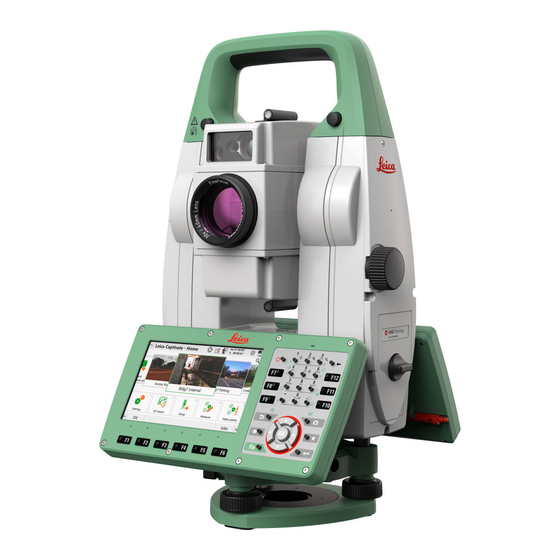
Page 35: Instrument Components
Instrument Components Instrument Carry handle a b c e f components Optical sight part 1 of 2 Telescope, integrating EDM, ATRplus, EGL, PS, overview camera EGL flashing diode - yellow and red Overview camera PowerSearch, transmitter PowerSearch, receiver Coaxial optics for angle and distance measurement, and exit port of visible laser beam for distance measurements SD Card and USB stick... - Page 36 Communication Side Cover Compartment lid USB stick cap storage USB device port (mini AB OTG) USB host port for USB stick SD card port 008623_001 Instrument GS15 SmartAntenna components for GS14/GS16 SmartAntenna SmartStation RTK slot-in device GAD110 SmartAntenna Adapter Communication side cover 008624_002 Instrument components for...
- Page 37 Laser guide compon- b c d b d e ents Operation indicator LED, orange Labelling Horizontal adjustment screws Fixing screws Safety cover for vertical adjustment screws Laser aperture TS_122 Description of the System...
-
Page 38: User Interface
User Interface Keyboard Keyboard Function keys F1-F6 Function keys F7-F12 ON/OFF Alphanumeric keys Backspace Home Arrow keys 0008626_002 Enter Favourites Camera Keys Function Function Correspond to six softkeys that appear on keys the bottom of the screen when the screen is F1 to F6 activated. -
Page 39: Operating Principles
Function Selects the highlighted line and leads to the next logical menu / dialog. Starts the edit mode for editable fields. Opens a selectable list. Backspace Deletes the job in the centre of the job carousel. Key combinations Function Hold Fn while pressing Switch to Windows. - Page 40 Operation Description To start the edit mode in editable Tap on the editable field. fields To highlight an item or parts of it for Drag the supplied stylus from the editing left to the right. To accept data entered into an edit- Tap on the screen outside of the able field and exit the edit mode editable field.
-
Page 41: Operation
Operation Setting Up the TS Instrument Instrument setup step-by-step 008639_001 Shield the instrument from direct sunlight and avoid uneven temper- ☞ atures around the instrument. Extend the tripod legs to allow for a comfortable working posture. Position the tripod above the marked ground point, centring it as good as possible. -
Page 42: Setting Up Smartstation
Setting Up SmartStation SmartStation setup step-by-step 008640_001 008641_002 Place the GAD110 adapter for the GS15/GS14/GS16 antenna onto the instrument by simultaneously pressing and holding-in the four push buttons. Ensure that the interface connection on the underside of the ☞ adapter is on the same side as the Communication side cover. Place the GS15/GS14/GS16 antenna onto the adapter by simultan- eously pressing and holding-in the two press clips. -
Page 43: Setting Up Smartpole
Mounting base radio The GHT43 tripod adapter is used to mount the TCPS29/30 to all to tripod step-by- Leica standard tripods, and to optimise the radio transmission per- step formance. Attach the TCPS29/30 to the adapter and then attach the adapter to the tripod leg. -
Page 44: Fixing The Field Controller To A Holder And Pole
Adjust the angle of TCPS29/30 until it is vertical. Adjust the location of the adapter on the tripod leg so that there are no metallic objects in the horizontal plane around the antenna. ☞ Metallic objects near the antenna disturb radio transmis- sions. - Page 45 Before placing the CS field controller onto the mounting plate, ensure that the locking pin is put into the unlocked position. To unlock the locking pin, push the locking pin to the left. 008546_001 Hold the CS field controller above the holder and lower the end of the CS field controller into the mounting plate.
-
Page 46: Fixing The Cs35 Tablet To A Holder And Pole
Fixing the CS35 Tablet to a Holder and Pole Components of For fixing the CS35 tablet to a pole you need the following components: GHT63 clamp and GHT63 clamp GHT78 holder Plastic sleeve Pole clamp Clamp bolt GHT78 holder Locking lever Mounting arm Mounting brackets 009241_001... -
Page 47: Connecting To A Personal Computer
Windows mobile-based pocket PC. WMDC enables a PC and a Windows mobile-based pocket PC to communicate. Leica USB drivers support Windows 7, Windows 8 (8.1) and Windows 10 oper- ating systems. Cables Leica USB drivers support:... - Page 48 Start the PC. drivers Run the Setup_Leica_USB_XXbit.exe to install the drivers necessary for Leica devices. Depending on the version (32bit or 64bit) of the operating system on your PC, you have to select between the three setup files following: Setup_Leica_USB_32bit.exe •...
- Page 49 Click Next>. The Ready to Install the Program window appears. Click Install. The drivers will be installed on your PC. The InstallShield Wizard Completed window appears. Click Finish to exit the wizard. Connect to PC via USB Start the PC. cable step-by-step Plug the cable into the instrument.
-
Page 50: Power Functions
A file browser opens. You can now browse within the folders on the instrument. Power Functions Turning the Press and hold power key ( ) for 2s. instrument on The instrument must have a power supply. ☞ Turning the Press and hold power key ( ) for 2 s. -
Page 51: Batteries
For Li-Ion batteries, a single discharging and charging cycle is sufficient. • We recommend carrying out the process when the battery capacity indic- ated on the charger or on a Leica Geosystems product deviates signific- antly from the actual battery capacity available. Operation/discharging The batteries can be operated from −20 °C to +55 °C/−4 °F to +131 °F. -
Page 52: Working With The Memory Device
Place the battery into the battery housing, ensuring that the con- tacts are facing outward. Click the battery into position. Place the battery housing into the battery compartment. Push the battery housing in until it fits completely into the battery compart- ment. -
Page 53: Led Indicators
Open the lid of the communication compartment to access the com- munication ports. Slide the USB stick with the Leica logo facing you firmly into the USB host port until it clicks into position. ☞... -
Page 54: Guidelines For Correct Results
Diagram of the LED Indicators a b c d Power LED Link LED Data Transfer LED Mode LED 008660_001 Description of the LED Indicators IF the THEN Power LED power is off. green power is on. Link LED no radio link to field controller. radio link to field controller. - Page 55 is triggered, the measurement may be made to the side of the vehicle. The result is the distance to the vehicle, not to the surface of the building. If using the long range measurement mode (> 1000 m, > 3300 ft) to prisms, and an object passes within 30 m of the EDM as the measurement is triggered, the distance measurement may be similarly effected due to the strength of the laser signal.
-
Page 56: Check & Adjust
Check & Adjust Overview Description Leica Geosystems instruments are manufactured, assembled and adjusted to the best possible quality. Quick temperature changes, shock or stress can cause deviations and decrease the instrument accuracy. It is therefore recom- mended to check and adjust the instrument from time to time. This check and adjust can be done in the field by running through specific measurement pro- cedures. -
Page 57: Preparation
During the manufacturing process, the instrument errors are carefully determ- ☞ ined and set to zero. As mentioned above, these errors can change and it is highly recommended to redetermine them in the following situations: Before the first use • Before every high precision survey •... -
Page 58: Combined Adjustment
ATRplus zero point error for vertical angle option Combined adjustment The following table explains the most common settings. procedure step-by- Leica Captivate - Home: Settings\TS instrument\Check & adjust step Check & Adjust Select the option: Check & adjust the compensator, index error, line of sight error &... - Page 59 ATRplus is available, the adjust- ment will include the determina- tion of the ATRplus Hz and V adjustment errors. ☞ Use a clean Leica standard prism as the ± 9° target. Do not use a 360° prism. 008371_001 Measure to measure and to continue to the next screen.
-
Page 60: Tilting Axis Adjustment (A)
Determine the horizontal collimation error (c) before starting this ☞ by-step procedure. Leica Captivate - Home: Settings\TS instrument\Check & adjust Check & Adjust Select the option: Check & adjust the tilting axis Face I measurement Aim the telescope accurately at a target at about 100 m dis- tance (or at least 20 m). - Page 61 Measure to measure and to continue to the next screen. Motorised instruments change automatically to the other face. 180° Non-motorised instruments guide to the other face. ☞ The fine pointing must be performed manu- 180° ally in both faces. 008372_001 Face II measurement Measure to measure the same target in the other face and to cal- culate the tilting axis error.
-
Page 62: Adjusting The Circular Level Of The Instrument And Tribrach
Adjusting the Circular Level of the Instrument and Tribrach Adjusting the circular level step-by-step 0016261_001 Place and secure the instrument into the tribrach and onto a tripod. Using the tribrach footscrews, level the instrument with the elec- tronic level. Select Settings\TS instrument\Level & compensator to access the Level &... -
Page 63: Adjusting The Circular Level Of The Prism Pole
The laser plummet is located in the vertical axis of the instrument. Under nor- ☞ mal conditions of use, the laser plummet does not need adjusting. If an adjustment is necessary due to external influences, return the instrument to any Leica Geosystems authorised service workshop. Inspecting the laser plummet step-by-step 360°... -
Page 64: Adjusting The Laser Guide
3 mm away from the point which was first marked, an adjustment may be required. Inform your nearest Leica Geosystems authorised service centre. Depending on bright- ness and surface, the diameter of the laser dot can vary. At 1.5 m, it is about 2.5 mm. - Page 65 Laser guide screws Horizontal adjustment screw Fixing screw Fixing screw Horizontal adjustment screw Vertical adjustment screw Vertical adjustment screw Safety cover screw Safety cover TS_124 Laser Guide adjust- This step-by-step description describes the Laser Guide adjustment for a dis- ment step-by-step tance of 50 m.
-
Page 66: Servicing The Tripod
Step Description ☞ The laser beam of an adjusted laser guide matches exactly the circle of 50 m or 120 m depending on the distance. Servicing the Tripod Servicing the tripod step-by-step 008706_001 The following table explains the most common settings. The connections between metal and timber components must ☞... -
Page 67: Care And Transport
Shipping When transporting the product by rail, air or sea, always use the complete ori- ginal Leica Geosystems packaging, container and cardboard box, or its equival- ent, to protect against shock and vibration. Shipping, transport of When transporting or shipping batteries, the person responsible for the... -
Page 68: Cleaning And Drying
An inspection of the motorisation in motorised instruments must be done in a ☞ Leica Geosystems authorised service centre. Leica Geosystems recommends an inspection of the product every 12 months. For instruments which are in intensive or permanent use, for example tunnel- ling or monitoring, the recommended inspection cycle may be reduced. -
Page 69: Technical Data
Technical Data Angle Measurement Accuracy Available angular Standard deviation Display resolution accuracies Hz, V ISO 17123-3 ["] [mgon] ["] [°] [mgon] [mil] 0.0001 0.01 0.0001 0.01 0.0001 0.01 0.0001 0.01 Characteristics Absolute, continuous, diametric. Distance Measurement with Reflectors Range Reflector Range A Range B Range C... -
Page 70: Distance Measurement Without Reflectors
Accuracy Accuracy refers to measurements to standard prisms. Distance Standard Standard Measurement measuring deviation deviation time, typical [s] mode ISO 17123-4, ISO 17123-4, standard prism tape Once 1 mm + 1.5 ppm 3 mm + 2 ppm Once & fast 2 mm + 1.5 ppm 3 mm + 2 ppm Continuously... -
Page 71: Distance Measurement - Long Range (Lo Mode)
Range Description Underground, night and twilight Accuracy ISO17123-4 Measure time, Measure time, typical [s] maximum [s] 0-500 2 mm + 2 ppm >500m 4 mm + 2 ppm Up to 50 m Object in shade, sky overcast. Beam interruptions, severe heat shimmer and moving objects within the beam path can result in deviations of the specified accuracy. -
Page 72: Automatic Target Aiming (Atrplus)
Accuracy Standard measur- Standard Measure time, Measure time, deviation typical [s] maximum [s] ISO 17123-4 Long Range 5 mm + 2 ppm Beam interruptions, severe heat shimmer and moving objects within the beam path can result in deviations of the specified accuracy. The display resolution is 0.1 mm. -
Page 73: Powersearch (Ps)
Maximum speed in Direction of prism movement lock mode Tangential Radial Prism Lock only 14 m/s at 20 m 25 m/s Prism Lock with 6 m/s at 20 m 6 m/s Measure distance: Continuously A tangential movement means the prism is passing by the instrument ☞... -
Page 74: Loc8 Theft Deterrence And Location Device (Optional)
Type Description Type Infrared laser LOC8 Theft Deterrence and Location Device (optional) Internal battery Battery Voltage Capacity Li-Ion 800 mAh Up to 5 days Recharged by the total sta- Depending on mode of oper- tion battery when instrument ation and cellular network is switched on conditions Tracking period... -
Page 75: Smartstation Dimensions
* Might vary due to atmospheric conditions, signal multipath, obstructions, signal geometry and number of tracked signals. RTK data formats Formats for data reception: Leica, Leica 4G, CMR, CMR+, RTCM 2.2, 2.3, 3.0, 3.1, 3.2 MSM 7.9.2 SmartStation Dimensions SmartStation... -
Page 76: Laser Guide Technical Data
With GS14/GS16 190 mm 226 mm 111.5 mm 111.5 mm 223 mm 008664_001 7.10 Laser Guide Technical Data Concept Telescope for dual face measurement • User adjustment for laser beam • Laser Type Description Type Visible, red, laser class 3R Carrier wave 658 nm Optics... -
Page 77: Conformity To National Regulations
Conformity to FCC Part 15 (applicable in US) • national regulations Hereby, Leica Geosystems AG declares that the radio equipment type • TS16 is in compliance with Directive 2014/53/EU and other applicable European Directives. The full text of the EU declaration of conformity is available at the fol- lowing Internet address: http://www.leica-geosystems.com/ce. -
Page 78: Radiohandle
2400–2500 2400–2500 7.11.2 RadioHandle Conformity to Hereby, Leica Geosystems AG declares that the radio equipment type • national regulations RadioHandle is in compliance with Directive 2014/53/EU and other applicable European Directives. The full text of the EU declaration of conformity is available at the fol- lowing Internet address: http://www.leica-geosystems.com/ce. -
Page 79: Dangerous Goods Regulations
Leica Geosystems has developed Guidelines on “How to carry Leica ☞ products” and “How to ship Leica products” with Lithium batteries. Before any transportation of a Leica product, we ask you to consult these guidelines on our web page (http://www.leica-geosystems.com/dgr) to ensure that you are in accordance with the IATA Dangerous Goods Regulations and that the Leica products can be transported correctly. -
Page 80: General Technical Data Of The Product
7.12 General Technical Data of the Product System accuracy Several factors can influence the accuracy of the system for determining the location of a prism: Internal ATRplus accuracy • Angular accuracy of the instrument • Type and centring accuracy of the prism •... - Page 81 360° prism 2.0 mm Leica GRZ4 360° prism 5.0 mm Refer to the white paper "Leica Surveying Reflectors" for information ☞ about the different centring accuracies. More influencing factors When determining absolute coordinates, the following parameters can also affect the resulting accuracy: Environmental conditions: temperature, air pressure and humidity •...
- Page 82 Type Description Keyboard 37 keys Including 12 function keys and 12 alphanu- meric keys, illumination Angle display 360°’", 360° decimal, 400 gon, 6400 mil, V % Distance display m, ft int, ft us, ft int inch, ft us inch Position Face I: Standard Face II: Optional Touch screen...
- Page 83 Instrument 177 mm dimensions 226 mm 111.5 mm 111.5 mm 223 mm 008605_001 With RH16/RH17 72 mm 226 mm 111.5 mm 111.5 mm 223 mm 008618_001 Weight Type Value Instrument 5.1 - 5.8 kg Tribrach 0.8 kg Internal battery 0.2 kg Recording Data can be recorded onto an SD card or into internal memory.
- Page 84 Avoid dirt on cover glass. ☞ ☞ Avoid line-of-sight obstructions. The full spot needs to be on target. For best performance use the new Leica tripods. For older tripods, ☞ an upgrade of the screw is recommended. Laser plummet Type...
- Page 85 Type Operating temperature Storage temperature [°C] [°C] Leica SD cards −40 to +80 −40 to +80 Battery internal −20 to +55 −40 to +70 Protection against water, dust and sand Type Protection All instruments IP55 (IEC 60529) Humidity Type Protection...
-
Page 86: Scale Correction
Automatic corrections The following automatic corrections are made: Line of sight error • Tilting axis error • Earth curvature • Circle eccentricity • Compensator index error • Vertical index error • Standing axis tilt • Refraction • ATRplus zero point error •... - Page 87 The index n is calculated from the formula of the IAG Resolutions (1999), and is valid for: Air pressure p: 1013.25 mbar Air temperature t: 12 °C Relative air humidity h: Formulas Formula for visible red laser 0.29535 · p 4.126 ·...
- Page 88 Atmospheric Atmospheric corrections in ppm with temperature [°C], air pressure [mb] and corrections °C height [m] at 60% relative humidity. 550 mb 1000 1050 mb 50°C 50°C 40°C 40°C 30°C 30°C 20°C 20°C 10°C 10°C 0°C 0°C -10°C -10°C -20°C -20°C 550 mb 1000 1050 mb...
-
Page 89: Reduction Formulas
7.14 Reduction Formulas Formulas Mean Sea Level Instrument Reflector Slope distance Horizontal distance Height difference TS_110 The instrument calculates the slope distance, horizontal distance, height dif- ference in accordance with the following formulas: = D 0 · ( 1 + ppm · 10 ) + AC 002425_002 Displayed slope distance [m]... - Page 90 Formulas Mean Sea Level Instrument Reflector Slope distance Horizontal distance Height difference TS_110 The instrument calculates the slope distance, horizontal distance, height dif- ference in accordance with the following formulas: = D 0 · ( 1 + ppm · 10 ) + AC 002425_002 Displayed slope distance [m]...
- Page 91 · ∑ D i = 1 TS_114 Slope distance as arithmetic mean of all measurements å Single slope distance measurement Number of measurements ∑ ∑ ∑ - D) i = 1 i = 1 i = 1 n - 1 n - 1 TS_115 Standard deviation of a single slope distance measurement...
-
Page 92: Software Licence Agreement/Warranty
Rights, Limitation of Liability, Exclusion of other Assurances, Governing Law and Place of Jurisdiction. Please make sure, that at any time you fully comply with the terms and conditions of the Leica Geosystems Software Licence Agreement. Such agreement is provided together with all products and can also be referred to and downloaded at the Leica Geosystems home page at http://leica-geosystems.com/about-us/compliance-standards/legal-documents... - Page 94 819218-4.1.0en Original text (819218-4.1.0en) Published in Switzerland © 2020 Leica Geosystems AG, Heerbrugg, Switzerland Leica Geosystems AG Heinrich-Wild-Strasse CH-9435 Heerbrugg Switzerland Phone +41 71 727 31 31 www.leica-geosystems.com...
Need help?
Do you have a question about the Viva TS16 and is the answer not in the manual?
Questions and answers
offset to vertical line with slop TS16
how to set range in TS16