Table of Contents
Advertisement
Quick Links
Advertisement
Table of Contents

Related Manuals for Leica TS12P


Summary of Contents for Leica TS12P
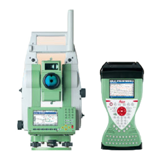
- Page 1 Leica TS12P User Manual Version 1.0 English...
- Page 2 Product Identifica- The type and serial number of your product are indicated on the type plate. tion Always refer to this information when you need to contact your agency or Leica Geosystems authorised service workshop. Trademarks • CompactFlash and CF are trademarks of SanDisk Corporation ®...
- Page 3 Service Description myProducts Add all Leica Geosystems products that you and your company own. View detailed information on your products, buy additional options or Customer Care Packages (CCPs), update your products with the latest software and keep up-to-date with the latest documentation.
-
Page 4: Table Of Contents
Fixing the Field Controller to a Holder and Pole Autodetect Behaviour Instrument Setup for Remote Control 4.6.1 Remote Control Setup 4.6.2 LED Indicators on RadioHandle Batteries 4.7.1 Operating Principles 4.7.2 Instrument Battery Working with the CompactFlash Card Guidelines for Correct Results TS12P, Table of Contents... - Page 5 Automatic Target Aiming ATR PowerSearch PS Conformity to National Regulations 7.7.1 Communication side cover with Bluetooth 7.7.2 RadioHandle 7.7.3 Dangerous Goods Regulations General Technical Data of the Instrument Scale Correction 7.10 Reduction Formulas Software Licence Agreement TS12P, Table of Contents...
-
Page 6: Safety Directions
Local safety authorities and safety experts must be contacted before working in DANGER hazardous areas, or close to electrical installations or similar situations by the person in charge of the product. TS12P, Safety Directions... -
Page 7: Responsibilities
• To ensure that it is used in accordance with the instructions. • To be familiar with local regulations relating to safety and accident prevention. • To inform Leica Geosystems immediately if the product and the application becomes unsafe. • To ensure that the national laws, regulations and conditions for the operation of e.g. - Page 8 Precautions: Make sure that the battery terminals do not come into contact with metallic objects. TS12P, Safety Directions...
- Page 9 Product-specific treatment and waste management information can be downloaded from the Leica Geosystems home page at http://www.leica- geosystems.com/treatment or received from your Leica Geosystems dealer. Only Leica Geosystems authorised service workshops are entitled to repair these prod- WARNING ucts. TS12P, Safety Directions...
-
Page 10: Laser Classification
User Manual. Description Value Wavelength 658 nm Pulse duration 800 ps Pulse repetition frequency (PRF) 100 MHz Maximum average radiant power 0.33 mW Beam divergance 1.5 mrad x 3 mrad Labelling a) Laser beam 002916_002 TS12P, Safety Directions... -
Page 11: Distancer, Measurements Without Reflectors
2) Do not look through or beside the optical sight at prisms or reflecting objects when the laser is switched on, in laser pointer or distance measurement mode. Aiming at prisms is only permitted when looking through the telescope. TS12P, Safety Directions... - Page 12 Operation is subject to the following two conditions: (1) This device may not cause harmful interference, and (2) This device must accept any interference received, including interference that may cause undesired operation. λ = 658nm Pav = 4.8mW tp = 800ps IEC 60825-1:2014 002763_002 TS12P, Safety Directions...
-
Page 13: Red Laser Pointer
2) Do not look through or beside the optical sight at prisms or reflecting objects when the laser is switched on, in laser pointer or distance measurement mode. Aiming at prisms is only permitted when looking through the telescope. TS12P, Safety Directions... - Page 14 Operation is subject to the following two conditions: (1) This device may not cause harmful interference, and (2) This device must accept any interference received, including interference that may cause undesired operation. λ = 658nm Pav = 4.8mW tp = 800ps IEC 60825-1:2014 002763_002 TS12P, Safety Directions...
-
Page 15: Automatic Target Aiming Atr
User Manual. Description Value Wavelength 785 nm Maximum average radiant power 3 mW 17 ms Pulse duration 29 Hz Pulse repetition frequency (PRF) Beam divergence 11 mrad Labelling a) Laser beam 002916_002 TS12P, Safety Directions... -
Page 16: Powersearch Ps
User Manual. Description Value Wavelength 850 nm Maximum average radiant power 11 mW Pulse duration 20 ns, 40 ns Pulse repetition frequency (PRF) 24.4 kHz Beam divergance 0.4 mrad x 700 mrad Labelling a) Laser beam 002918_002 TS12P, Safety Directions... -
Page 17: Electronic Guide Light Egl
The product described in this section, is classified as exempt group in accord- ance with IEC 62471 (2006-07) and does not pose any hazard provided that the product is used and maintained in accordance with this user manual. a) LED beam red b) LED beam yellow 002919_002 TS12P, Safety Directions... -
Page 18: Laser Plummet
Do not stare into the beam Class 2 Laser Product according to IEC 60825-1 (2014 - 05) = 0.95 mW = 640 nm tp = 10 ms - cw TS12_048 a) Laser beam b) Exit for laser beam TS12P, Safety Directions... -
Page 19: Electromagnetic Compatibility Emc
WARNING Although the product meets the strict regulations and standards which are in force in this respect, Leica Geosystems cannot completely exclude the possibility that other equipment may be disturbed. There is a risk that disturbances may be caused in other equipment if the product is... -
Page 20: Fcc Statement, Applicable In U
• Connect the equipment into an outlet on a circuit different from that to which the receiver is connected. • Consult the dealer or an experienced radio/TV technician for help. Changes or modifications not expressly approved by Leica Geosystems for compliance WARNING could void the user's authority to operate the equipment. - Page 21 Labelling RH16 RadioHandle 008612_001 RH17 008613_001 TS12P, Safety Directions...
-
Page 22: Description Of The System
Motorised. Automated Target Aiming. ATR refers to the instrument sensor which enables the automatic target aiming to a prism. Automated Instruments fitted with Target aiming are referred to as Auto- mated. TS12P, Description of the System... -
Page 23: System Concept
• By connecting the CompactFlash card directly to the computer either via an internal card slot housing or an external OMNI drive, the software is transferred to the card, which is then stored to the System RAM. TS12P, Description of the System... -
Page 24: Data Storage And Data Conversion Concept
Data can be exported from a job in a wide range of ASCII formats. The export format is defined in Format Manager which is a PC tool in Leica Geo Office. Refer to the online help of LGO for information on creating format files. -
Page 25: Container Contents
Counterweight for diagonal eyepiece f) Instrument with tribrach and standard handle or RadioHandle g) Protective cover for instrument, sunshade for objective lens and cleaning cloth h) Allen key i) GEB222 battery j) GMP101 mini prism TS12P, Description of the System... - Page 26 Spare stylus c) Manuals & USB documentation card d) SD cards/CompactFlash cards and covers e) Tip for mini prism f) Battery charger g) Car adapter power plug for battery charger (stored under battery charger) * Optional TS12P, Description of the System...
- Page 27 GRZ101 mini prism and GAD103 adapter h) GEB212 battery i) Field controller with CTR j) GHT62 holder (extended) k) GLI115, clip-on bubble for mini pole l) GLS115 mini pole m) Spare stylus n) GHT63 clamp TS12P, Description of the System...
-
Page 28: Instrument Components
Tribrach securing screw TS12_001a Instrument components part 2 of 2 k) Vertical drive l) Focusing ring m) Battery compartment n) Stylus for touch screen o) Screen p) Circular level q) Tribrach footscrew r) Eyepiece s) Keyboard TS12_001b TS12P, Description of the System... - Page 29 Instrument c omponents for RCS a) RadioHandle b) Communication side cover TPS12_199 TS12P, Description of the System...
-
Page 30: User Interface
Function keys F1-F6 • Correspond to the six softkeys that appear on the bottom of the screen when the screen is activated. Key combinations Keys Description ON plus USER Turns instrument off. Pages up. SHIFT Pages down. SHIFT TS12P, User Interface... -
Page 31: Screen
SHIFT. Softkeys Commands can be executed using (F1)-(F6) keys. The commands assigned to the softkeys are screen-dependent. Can be used directly with touch screen. Scroll bar Scrolls the screen area up and down. TS12P, User Interface... -
Page 32: Operating Principles
Tap on the page tab with the stylus. Edit an entire value Appearance Description in input fields 1) Highlight the field. 2) Type numeric and/or alphanumeric characters to overwrite. 3) ENTER or tap outside of the field. TS12P, User Interface... - Page 33 Toggle to the desired special character set by using the up/down arrow keys. Press the function key assigned to the required character group. Press the function key with the required character. Repeat step 4. and 5. for entering more special characters of the same char- acter set. ENTER. TS12P, User Interface...
- Page 34 • To exit without changes press ESC or tap . • A scroll bar is shown if necessary. • The functionality comprises adding, editing and deleting of items. • Listbox dialogs are explained in detail at appropriate places in the manuals. TS12P, User Interface...
-
Page 35: Icons
SHIFT The status of the SHIFT key is displayed. Quick coding Shows the quick coding configuration. Can be used with touch screen to turn quick coding on and off. TS12P, User Interface... -
Page 36: Operation
By using the electronic level turn the tribrach footscrews (6) to precisely level the instrument. Centre the instrument precisely over the ground point (4) by shifting the tribrach on the tripod plate (2). Repeat steps 6. and 7. until the required accuracy is achieved. TS12P, Operation... -
Page 37: Setting Up Smartpole
Setting up for Remote Control (with the RadioHandle) Setup for remote control with RadioHandle a) 360° prism b) Prism pole c) CTR radio cap d) Field controller e) GHT62 holder and GHT63 clamp f) RadioHandle g) Communication side cover h) Instrument i) Tripod TS_144 TS12P, Operation... -
Page 38: Fixing The Field Controller To A Holder And Pole
Apply slight pressure in a downward direction and then lower the top part of the field controller until the unit is clicked into the holder. The guides of the mounting plate aid in this action. TS_056 TS12P, Operation... - Page 39 Place palm over the top of the field controller until fingers grip the bar of the holder underneath. Push from the top of the field controller toward the bar of the holder. While in this position, lift the top of the field controller from the holder. TS_057 TS12P, Operation...
-
Page 40: Autodetect Behaviour
Ensure that the interface connection on the underside of the RadioHandle is on the same side as the Communication side cover. Swing the RadioHandle antenna into an upright position. Refer to "CS15 User Manual" for additional information. TS12P, Operation... -
Page 41: Led Indicators On Radiohandle
Link LED no radio link to remote controller. radio link to remote controller. Data Transfer LED no data transfer to/from remote controller. green or green data transfer to/from remote controller. flashing Mode LED data mode. configuration mode. TS12P, Operation... -
Page 42: Batteries
+10°C to +20°C/+50°F to +68°F if possible. • It is normal for the battery to become warm during charging. Using the chargers recommended by Leica Geosystems, it is not possible to charge the battery if the temperature is too high. -
Page 43: Working With The Compactflash Card
CompactFlash card compartment. Press the card down on the lid. Close the lid. Turn the knob to lock the CompactFlash card compartment. The lid is closed correctly when the knob is turned to a horizontal position. TS12P, Operation... -
Page 44: Guidelines For Correct Results
If using the long range measurement mode (> 1000 m, > 3300 ft) to prisms, and an object passes within 30 m of the EDM as the measurement is triggered, the distance measurement may be similarly effected due to the strength of the laser signal. TS12P, Operation... - Page 45 If the prism location is changed too quickly, the target may be lost. Make sure that the speed does not exceed the figure given in the technical data. TS12P, Operation...
-
Page 46: Check & Adjust
Check & Adjust Overview Description Leica Geosystems instruments are manufactured, assembled and adjusted to the best possible quality. Quick temperature changes, shock or stress can cause deviations and decrease the instrument accuracy. It is therefore recommended to check and adjust the instrument from time to time. -
Page 47: Preparation
Refer to "5.5 Adjusting the Circular Level of the Instru- ment and Tribrach". adjust the laser/optical Refer to "5.7 Inspecting the Laser Plummet of the plummet Instrument". adjust the tripod Refer to "5.8 Servicing the Tripod". TS12P, Check & Adjust... -
Page 48: Combined Adjustment (L, T, I, C And Atr)
<ATR Adjust: On> Includes the determination of the ATR Hz and V adjust- ment errors if an ATR is available. It is recommended to use a clean Leica circular prism as target. Do not use a 360° prism. Aim the telescope accurately at a target at about 100 m distant. - Page 49 Use status is set to Yes. to be determined REDO (F2) rejects all new determined adjustment errors and again repeats the whole procedure. Refer to step 3. of paragraph "Combined adjustment procedure step by step". TS12P, Check & Adjust...
-
Page 50: Tilting Axis Adjustment (A)
If the error is bigger than the predefined limit, the procedure has to be repeated. The tilting axis measurements of the current run are then rejected and not averaged with the results from previous runs. TS12P, Check & Adjust... - Page 51 Use status is set to Yes. to be determined REDO (F2) rejects all new determined adjustment errors and again repeats the whole procedure. Refer to step 3. of paragraph "Determination of tilting axis error step by step". TS12P, Check & Adjust...
-
Page 52: Adjusting The Circular Level Of The Instrument And Tribrach
If the circular level is not centred, use an allen key to centre it with the adjustment screws. After the adjustments, all adjusting screws must have the same tightening tension and no adjusting screw should be loose. TS12P, Check & Adjust... -
Page 53: Inspecting The Laser Plummet Of The Instrument
The laser plummet is located in the vertical axis of the instrument. Under normal condi- tions of use, the laser plummet does not need adjusting. If an adjustment is necessary due to external influences, return the instrument to any Leica Geosystems authorised service workshop. -
Page 54: Servicing The Tripod
Tighten the leg cap screws moderately, with the supplied allen key. Tighten the articulated joints on the tripod head enough to keep the tripod legs open when lifting the tripod off the ground. Tighten the allen screws of the tripod legs. TS12P, Check & Adjust... -
Page 55: Care And Transport
Shipping When transporting the product by rail, air or sea, always use the complete original Leica Geosystems packaging, transport container and cardboard box, or its equivalent, to protect against shock and vibration. Shipping, transport When transporting or shipping batteries, the person responsible for the product must... -
Page 56: Cleaning And Drying
Maintenance An inspection of the motorisation in motorised instruments must be done in a Leica Geosystems authorised service centre. Leica Geosystems recommends an inspection of the product every 12 months. For instruments which are in intensive or permanent use, for example tunnelling or monitoring, the recommended inspection cycle may be reduced. -
Page 57: Technical Data
Technical Data Angle Measurement Accuracy Available angular Standard deviation Hz, V, Display resolution accuracies ISO 17123-3 ["] [mgon] ["] [mgon] Characteristics Absolute, continuous, diametric. TS12P, Technical Data... -
Page 58: Distance Measurement With Reflectors
The display resolution is 0.1 mm. Characteristics Principle: Phase measurement Type: Coaxial, visible red laser Carrier wave: 658 nm Measuring system: System analyser basis 100 MHz - 150 MHz TS12P, Technical Data... -
Page 59: Distance Measurement Without Reflectors
658 nm Measuring system: System analyser basis 100 MHz - 150 MHz Laser dot size Distance [m] Laser dot size, approximately [mm] at 30 7 x 10 at 50 8 x 20 at 100 16 x 25 TS12P, Technical Data... -
Page 60: Distance Measurement - Long Range (Lo Mode)
The display resolution is 0.1 mm. Characteristics Principle: Phase measurement Type: Coaxial, visible red laser Carrier wave: 658 nm Measuring system: System analyser basis 100 MHz - 150 MHz TS12P, Technical Data... -
Page 61: Automatic Target Aiming Atr
± 1 mm. • The following graph shows the ATR standard deviation based on three different prism types, distances and instrument accuracies. 5” 3” 2” GRZ4 1” GRZ122 003744_001 Leica GRZ4 prism (360°) Leica GRZ122 prism (360°) TS12P, Technical Data... -
Page 62: Powersearch Ps
Leica circular prisms and Leica circular Mini prisms ATR accuracy [mm] Distance measurement [m] " Instrument angle accuracy ["] Maximum speed in Maximum tangential speed: 5 m/s at 20 m; 25 m/s at 100 m lock mode Maximum radial speed with 5 m/s <EDM Mode: Tracking>... -
Page 63: Conformity To National Regulations
• FCC Part 15 (applicable in US). national regulations • Hereby, Leica Geosystems AG, declares that the instrument with Communication side cover is in compliance with the essential requirements and other relevant provisions of Directive 1999/5/EC and other applicable European Directives. The declaration of conformity may be consulted at http://www.leica-geosys-... -
Page 64: Radiohandle
Leica Geosystems has developed Guidelines on “How to carry Leica products” and “How to ship Leica products” with Lithium batteries. Before any transpor- tation of a Leica product, we ask you to consult these guidelines on our web page (http://www.leica-geosystems.com/dgr) to ensure that you are in accord- ance with the IATA Dangerous Goods Regulations and that the Leica products can be transported correctly. -
Page 65: General Technical Data Of The Instrument
Port 2 Handle • Hotshoe connection for RadioHandle with RCS. • This port is located on top of Communication side cover. Port 3 • Bluetooth module for communication. • This port is housed within Communication side cover. TS12P, Technical Data... - Page 66 50 gon/s Power External supply voltage: Nominal voltage 12.8 V DC, Range 11.5 V-13.5 V Internal Battery Type: Li-Ion Voltage: 7.4 V Capacity: GEB222: 6.0 Ah External battery Type: NiMH Voltage: 12 V Capacity: GEB371: 9.0 Ah TS12P, Technical Data...
- Page 67 The following automatic corrections are made: tions • Line of sight error • Vertical index error • Tilting axis error • Standing axis tilt • Earth curvature • Refraction • Circle eccentricity • ATR zero point error • Compensator index error TS12P, Technical Data...
-
Page 68: Scale Correction
[nm] combined EDM 1.0002863 The index n is calculated from the formula of the IAG Resolutions (1999), and is valid for: Air pressure p: 1013.25 mbar Air temperature t: 12 °C Relative air humidity h: 60 % TS12P, Technical Data... - Page 69 Projection distortion [ppm] ΔD · 10 Easting, distance from projection zero line with the scale factor 1 [km] TS_107 6.378 * 10 In countries where the scale factor is not unity, this formula cannot be directly applied. TS12P, Technical Data...
- Page 70 50°F 50°F 40°F 40°F 30°F 30°F 20°F 20°F 10°F 10°F 0°F 0°F -10°F -10°F -20°F -20°F 18 19 20 21 22 23 24 25 26 27 28 29 30 31 32 inch Hg [ ft ] TS_109 TS12P, Technical Data...
-
Page 71: Reduction Formulas
(radius of the earth) Earth curvature (1/R) and mean refraction coefficient (k) are automatically taken into account when calculating the horizontal distance and height difference. The calculated horizontal distance relates to the station height and not to the reflector height. TS12P, Technical Data... - Page 72 The standard deviation of the arithmetic mean of the distance can be calculated as follows: Standard deviation of the arithmetic mean of the distance TS_116 s Standard deviation of a single meas- urement n Number of measurements TS12P, Technical Data...
-
Page 73: Software Licence Agreement
Leica Geosystems. Such software is protected by copyright and other laws and its use is defined and regulated by the Leica Geosystems Software Licence Agreement, which covers aspects such as, but not limited to, Scope of the Licence, Warranty, Intellectual Property Rights, Limitation of Liability, Exclusion of other Assurances, Governing Law and Place of Jurisdiction. - Page 74 827621-1.0.0en Original text Printed in Switzerland © 2015 Leica Geosystems AG, Heerbrugg, Switzerland Leica Geosystems AG Heinrich-Wild-Strasse CH-9435 Heerbrugg Switzerland Phone +41 71 727 31 31 www.leica-geosystems.com...
Need help?
Do you have a question about the TS12P and is the answer not in the manual?
Questions and answers