Table of Contents
Advertisement
Advertisement
Table of Contents

Related Manuals for Leica TS11


Summary of Contents for Leica TS11
- Page 1 Leica TS11 User Manual Version 3.0 English...
- Page 2 The type and serial number of your product are indicated on the type plate. identification Enter the type and serial number in your manual and always refer to this information when you need to contact your agency or Leica Geosystems authorised service work- shop. Type: _______________ Serial No.:...
- Page 3 Service Description myProducts Add all Leica Geosystems products that you and your company own. View detailed information on your products, buy addi- tional options or Customer Care Packages (CCPs), update your products with the latest software and keep up-to-date with the latest documentation.
-
Page 4: Table Of Contents
Power Functions Batteries 4.9.1 Operating Principles 4.9.2 Battery for the TS Instrument 4.9.3 Battery for SmartAntenna 4.10 Working with the Memory Device 4.11 Working with the RTK Device (SmartStation) 4.12 LED Indicators 4.13 Guidelines for Correct Results TS11, Table of Contents... - Page 5 7.7.8 SLR3-1, SLR3-2, Pacific Crest ADL 7.7.9 SLG1, Telit UC864-G 7.7.10 SLG2, CINTERION MC75i 7.7.11 SLC1 (US), SLC2 (US) CDMA Telit CC864-DUAL General Technical Data of the Instrument Scale Correction 7.10 Reduction Formulas Software Licence Agreement TS11, Table of Contents...
-
Page 6: Safety Directions
Important paragraphs which must be adhered to in practice as they enable the product to be used in a technically correct and efficient manner. TS11, Safety Directions... -
Page 7: Definition Of Use
• To ensure that it is used in accordance with the instructions. • To be familiar with local regulations relating to safety and accident prevention. • To inform Leica Geosystems immediately if the product and the application becomes unsafe. • To ensure that the national laws, regulations and conditions for the operation of e.g. -
Page 8: Hazards Of Use
Be careful when pointing the product towards the sun, because the telescope func- CAUTION tions as a magnifying glass and can injure your eyes and/or cause damage inside the product. Precautions: Do not point the product directly at the sun. TS11, Safety Directions... - Page 9 Product-specific treatment and waste management information can be downloaded from the Leica Geosystems home page at http://www.leica- geosystems.com/treatment or received from your Leica Geosystems dealer. Only Leica Geosystems authorised service workshops are entitled to repair these prod- WARNING ucts. TS11, Safety Directions...
-
Page 10: Laser Classification
This device complies with part 15 of the FCC Rules. Operation is subject to the following two conditions: (1) This device may not cause harmful interference, and (2) this device must accept any interference received, including interference that may cause undesired operation. 003967_001 a) Laser beam TS11, Safety Directions... -
Page 11: Distancer, Measurements Without Reflectors
2) Do not look through or beside the optical sight at prisms or reflecting objects when the laser is switched on, in laser pointer or distance measurement mode. Aiming at prisms is only permitted when looking through the telescope. TS11, Safety Directions... -
Page 12: Electronic Guide Light Egl
The product described in this section, is classified as exempt group in accord- ance with IEC 62471 (2006-07) and does not pose any hazard provided that the product is used and maintained in accordance with this user manual. a) LED beam red b) LED beam yellow 003970_001 TS11, Safety Directions... -
Page 13: Laser Plummet
Do not stare into the beam Class 2 Laser Product according to IEC 60825-1 (2007 - 03) Po 1.00 mW = 620 - 690 nm 003971_001 a) Will be replaced by a class 3R warning label if applicable TS11, Safety Directions... -
Page 14: Electromagnetic Compatibility Emc
WARNING Although the product meets the strict regulations and standards which are in force in this respect, Leica Geosystems cannot completely exclude the possibility that other equipment may be disturbed. There is a risk that disturbances may be caused in other equipment if the product is... - Page 15 Precautions: Although the product meets the strict regulations and standards which are in force in this respect, Leica Geosystems cannot completely exclude the possibility that other equipment can be disturbed or that humans or animals can be affected. • Do not operate the product with radio or digital cellular phone devices in the vicinity of filling stations or chemical installations, or in other areas where an explosion hazard exists.
-
Page 16: Fcc Statement, Applicable In U
• Connect the equipment into an outlet on a circuit different from that to which the receiver is connected. • Consult the dealer or an experienced radio/TV technician for help. Changes or modifications not expressly approved by Leica Geosystems for compliance WARNING could void the user's authority to operate the equipment. - Page 17 (1) This device may not cause harmful interference, and (2) this device must accept any interference received, including interference that may cause undesired operation. GEB_002 Labelling internal battery GEB212 005044_001 TS11, Safety Directions...
-
Page 18: Description Of The System
System Components System components TS11 CS15 003963_001 General description TS11 is a collective term describing total stations of the Leica Viva Series. Main components Component Description TS11 instrument • a total station for measuring, calculating and capturing data. • consisting of various models with a range of accuracy classes. - Page 19 GS12/GS14/GS15. Where there are differences between the various models they are clearly described. Communication Communication side cover with integrated Bluetooth, SD card slot side cover and USB port is standard for a TS11 instrument and a component of a SmartStation. Available models ...
-
Page 20: System Concept
GeoC++ development kit in addition to run Windows CE-based applications if GeoCOM robotics (xx.axx) licence is available. Information on the GeoC++ development environment is available on request from a Leica Geosystems representative. Software upload Uploading software can take some time. Ensure that the battery is at least 75% full before beginning the upload, and do not remove the battery during the upload process. -
Page 21: Power Concept
Available capacity: 1 GB. While other SD cards can be used, Leica Geosystems recommends to only use Leica SD cards and is not responsible for data loss or any other error that can occur while using a non-Leica card. ... -
Page 22: Container Contents
Manuals & USB documentation card d) SD cards/CompactFlash cards and covers e) Tip for mini prism f) GKL211 battery charger g) Car adapter power plug for battery charger (stored under battery charger) * Optional 000599_004 TS11, Description of the System... - Page 23 GHT63 clamp d) Cables e) GDC221 car adapter for CS field controller f) GAD108 arm g) GAD110 adapter for GS15 antenna h) Manuals & USB documentation card i) GMP101 mini prism j) Mini prism spike 000597_002 TS11, Description of the System...
- Page 24 GDC221 car adapter for CS field controller e) Mini prism spike f) CGR10/CGR15 radio g) Radio antenna h) GAD104 adapter for GS12 antenna or GAD110 adapter for GS08plus/GS14 instrument i) Manuals & USB documentation card j) Cables 002506_003 TS11, Description of the System...
- Page 25 GRZ101 mini prism i) GAD103 adapter for GRZ101 mini prism j) GEB211/GEB212 battery k) GHT63 clamp l) Manuals & USB documentation card m) GLS115 mini pole n) GDC221 car adapter for CS field controller 004086_002 TS11, Description of the System...
-
Page 26: Instrument Components
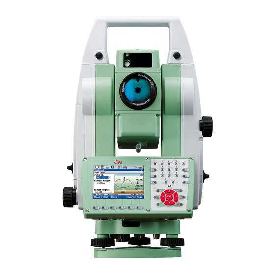
2 of 2 a) Vertical drive b) Focusing ring c) Battery compartment d) Tribrach footscrew e) Stylus for touch screen f) Touch screen g) Circular level h) Interchangeable eyepiece i) Keyboard e f g TS_082 TS11, Description of the System... - Page 27 USB host port for USB stick e) SD card port TS_089 Instrument components for SmartStation 002318_002 a) GS15 e) RTK slot-in device b) GS14 f) GAD110 SmartAntenna Adapter c) GS08plus g) Communication side cover d) GS12 h) GAD104 SmartAntenna Adapter TS11, Description of the System...
-
Page 28: User Interface
If the instrument is already off: Turns on the instrument when held for 2 s. If the instrument is already on: Turns to Power Options menu when held for 2 s. Favourites Goes to a favourites menu. TS11, User Interface... -
Page 29: Operating Principles
To accept data entered into an editable Tap on the screen outside of the editable field and exit the edit mode field. To open a context-sensitive menu Tap on the item and hold for 2 s. TS11, User Interface... -
Page 30: Operation
By using the electronic level, turn the tribrach footscrews (6) to level the instrument precisely. Centre the instrument precisely over the ground point (4) by shifting the tribrach on the tripod plate (2). Repeat steps 6. and 7. until the required accuracy is achieved. TS11, Operation... -
Page 31: Setting Up Smartstation
Ensure that the interface connection on the underside of the adapter is on the same side as the Communication side cover. 000606_003 Step Description Place the GS15/GS14/GS12/GS08plus antenna onto the adapter by simulta- neously pressing and holding-in the two press clips. TS11, Operation... -
Page 32: Setting Up Smartpole
GRZ122 360° prism c) CTR16 radio cap d) GLS12 cm/GLS12F ft pole with snap-lock positions e) CS15 field controller f) GHT62 holder and GHT63 clamp g) RH16 RadioHandle h) Communication side cover, integrated i) Instrument j) Tripod TS_147 TS11, Operation... -
Page 33: Setting Up For Remote Control (With The Radiohandle)
Setup for remote control with TCPS29 a) 360° prism b) Prism pole c) CTR16 radio cap d) CS15 field controller e) GHT62 holder and GHT63 clamp f) Instrument g) Tripod h) TCPS29 i) External battery j) Y-cable TS_145 TS11, Operation... - Page 34 Description tripod step-by-step The GHT43 tripod adapter is used to mount the TCPS29 to all Leica standard tripods, and to optimise the radio transmission performance. Attach the TCPS29 to the adapter and then attach the adapter to the tripod leg.
-
Page 35: Fixing The Cs To A Holder And Pole
Apply slight pressure in a downward direction and then lower the top part of the CS field controller until the unit is clicked into the holder. The guides of the mounting plate aid in this action. TS_056 TS11, Operation... - Page 36 Place palm over the top of the CS until fingers grip the bar of the holder underneath. Push from the top of the CS toward the bar of the holder. While in this position, lift the top of the CS from the holder. TS_057 TS11, Operation...
-
Page 37: Connecting To A Personal Computer
Insert the Leica Viva Series USB card. Run the SetupViva&GR_USB_XX.exe to install the drivers necessary for Leica Viva devices. Depending on the version (32bit or 64bit) of the oper- ating system on your PC, you have to select between the three setup files following: •... - Page 38 Allow USB connections inside the Connection Settings window of ActiveSync. For PCs with Windows Vista or Windows 7/Windows 8 operating system: Windows Mobile Device Center starts up automatically. If does not start automatically, start Windows Mobile Device Center. TS11, Operation...
- Page 39 The folders on the TS instrument are displayed under Mobile Devices. The folders of the data storage device can be found in either of the following folders: • Leica Geosystems\SmartWorx Viva • SD Card • USB memory device For PCs with Windows Vista or Windows 7/Windows 8 operating system: ...
-
Page 40: Power Functions
• Reset Windows CE (resets Windows CE and communication settings to factory defaults) • Reset installed software (resets settings of all installed software) • Reset Windows CE and installed software (resets Windows CE and settings of all installed software) TS11, Operation... -
Page 41: Batteries
+10°C to +20°C/+50°F to +68°F if possible. • It is normal for the battery to become warm during charging. Using the chargers recommended by Leica Geosystems, it is not possible to charge the battery if the temperature is too high. -
Page 42: Battery For Smartantenna
Place the battery onto the battery housing, ensuring that the contacts are facing outward. Click the battery into position. Place the battery housing into the battery compartment. Close the battery compartment by pushing the slide fastener in the direction of the arrow with the close-lock symbol. TS11, Operation... - Page 43 Place the battery onto the battery housing, ensuring that the contacts are facing outward. Click the battery into position. Place the battery housing into the battery compartment. Close the battery compartment by pushing the slide fastener in the direction of the arrow with the close-lock symbol. TS11, Operation...
- Page 44 Push the battery upwards so that it locks into position. Insert the cover of the battery compartment into the compartment. Push the slide fastener in the direction of the arrow with the close-lock symbol. TS11, Operation...
- Page 45 Push the battery upwards so that it locks into position. Insert the cover of the battery compartment into the compartment. Push the slide fastener in the direction of the arrow with the close-lock symbol. TS11, Operation...
-
Page 46: Working With The Memory Device
Open the lid of the communication compartment to access the communication ports. Slide the USB stick with the Leica logo facing you firmly into the USB host port until it clicks into posi- tion. ... - Page 47 Gently press on the top of the card to release it from the slot. Remove the SD card. Insert the cover into battery compartment 1. Push the slide fastener in the direction of the arrow with the close-lock symbol. TS11, Operation...
-
Page 48: Working With The Rtk Device (Smartstation)
This increases the height of the radio antenna and therefore maximises radio coverage. Refer to the Leica Viva GNSS Getting Started Guide for detailed information about the setup. - Page 49 Signal SLC1 (US), SLC2 device is on, not registered on strength (US) with CDMA the network. Telit CC864-DUAL flashing red device is on, registered on the network. download mode or device is off. TS11, Operation...
- Page 50 M3-TR1 flashing red the communication link, Data Carrier Detection, is okay on the roving instrument, but signal is weak. the DCD is not okay. Power LED any device power is off. green power is okay. TS11, Operation...
-
Page 51: Led Indicators
Power is 100% - 20%. Power is 20% - 5%. flashing red Power is low (<5%). The remaining time for which enough power is avail- able depends on the type of survey, the temperature and the age of the battery. TS11, Operation... - Page 52 5% memory left. SD card is full, no raw data is being logged. fast flashing red no SD card is inserted but GS15 is configured to log raw data. TS11, Operation...
- Page 53 GS15 is in RTK base mode. Data is being passed to the RX/TX interface of the communication device. *1 The battery, which currently powers the GS15 GNSS instrument. *2 Other batteries, which are inserted or connected but are not currently power the GS15 GNSS instrument. TS11, Operation...
-
Page 54: Guidelines For Correct Results
EDM may measure to the obstruction. Do not measure with two instruments to the same target simultaneously to avoid getting mixed return signals. TS11, Operation... -
Page 55: Check & Adjust
Check & Adjust Overview Description Leica Geosystems instruments are manufactured, assembled and adjusted to the best possible quality. Quick temperature changes, shock or stress can cause deviations and decrease the instrument accuracy. It is therefore recommended to check and adjust the instrument from time to time. -
Page 56: Preparation
Refer to "5.5 Adjusting the Circular Level of the Instru- ment and Tribrach". adjust the laser/optical Refer to "5.7 Inspecting the Laser Plummet of the plummet Instrument". adjust the tripod Refer to "5.8 Servicing the Tripod". TS11, Check & Adjust... -
Page 57: Combined Adjustment (L, T, I And C)
Select the option: Check & Adjust the compensator, index error & line of sight error Next Face I measurement Use a clean Leica standard prism as the target. Do not use a 360° prism. Aim the telescope accurately at a target at about 100 m distant. The target must be positioned within ±9°/±10 gon of the hori-... - Page 58 If the Use status is set to Yes, Next overwrites the old adjustment errors with the new ones. to be determined again Redo rejects all new determined adjustment errors and repeats the whole procedure. Refer to paragraph "Combined adjustment procedure step-by-step". TS11, Check & Adjust...
-
Page 59: Tilting Axis Adjustment (A)
The tilting axis measurements of the current run are then rejected and not averaged with the results from previous runs. Adjustment Status No. of measurements: Shows the number of runs completed. One run consists of a measurement in face I and face II. TS11, Check & Adjust... -
Page 60: Adjusting The Circular Level Of The Instrument And Tribrach
Tribrach: If it extends beyond the circle, use the supplied allen key to centre it with the adjustment screws. After the adjustments, all adjusting screws must have the same tightening tension and no adjusting screw should be loose. TS11, Check & Adjust... -
Page 61: Adjusting The Circular Level Of The Prism Pole
The laser plummet is located in the vertical axis of the instrument. Under normal conditions of use, the laser plummet does not need adjusting. If an adjustment is necessary due to external influences, return the instrument to any Leica Geosystems authorised service workshop. -
Page 62: Servicing The Tripod
Tighten the leg cap screws moderately, with the supplied allen key. Tighten the articulated joints on the tripod head enough to keep the tripod legs open when lifting the tripod off the ground. Tighten the allen screws of the tripod legs. TS11, Check & Adjust... -
Page 63: Care And Transport
Shipping When transporting the product by rail, air or sea, always use the complete original Leica Geosystems packaging, transport container and cardboard box, or its equivalent, to protect against shock and vibration. Shipping, transport When transporting or shipping batteries, the person in charge of the product must... -
Page 64: Cleaning And Drying
Always close the transport container when using in the field. Cables and plugs Keep plugs clean and dry. Blow away any dirt lodged in the plugs of the connecting cables. Connectors with Wet connectors must be dry before attaching the dust cap. dust caps TS11, Care and Transport... -
Page 65: Technical Data
3 mm + 1.5 ppm 3 mm + 2 ppm < 0.15 Continuous Beam interruptions, severe heat shimmer and moving objects within the beam path can result in deviations of the specified accuracy. The display resolution is 0.1 mm. TS11, Technical Data... -
Page 66: Distance Measurement Without Reflectors
658 nm Measuring system: System analyser basis 100 MHz - 150 MHz Laser dot size Distance [m] Laser dot size, approximately [mm] at 30 7 x 10 at 50 8 x 20 at 100 16 x 25 TS11, Technical Data... -
Page 67: Distance Measurement - Long Range (Lo Mode)
7.5 m (24.6 ft) to infinity at zoom level 4 x Image storage: JPEG up to 5 Mpixel (2560 x 1920) Zoom: 4-step (1x, 2x, 4x, 8x) Whitebalance: Automatic and user configurable Brightness: Automatic and user configurable TS11, Technical Data... -
Page 68: Smartstation
* Might vary due to atmospheric conditions, signal multipath, obstructions, signal geometry and number of tracked signals. RTK data formats Formats for data reception: Leica proprietary GPS and GNSS real-time data formats, CMR, CMR+, RTCM V2.1 / 2.2 / 2.3 / 3.1 7.6.2... -
Page 69: Smartantenna Technical Data
Leica Viva TPS instruments. GS12 L1, L2, L5 GPS, GLONASS, Galileo With CS10/CS15 field SmartTrack+ antenna. controller or Leica Viva TPS instruments. GS14 GPS, GLONASS, Galileo, BeiDou With CS10/CS15 field SmartTrack+ antenna with built in controller or Leica Viva TPS groundplane. - Page 70 Waterproof to 1 m temporary immersion Tested for 2 hours in 1.40 m depth Humidity Protection Up to 100 % The effects of condensation are to be effectively counteracted by periodically drying out the antenna. TS11, Technical Data...
-
Page 71: Conformity To National Regulations
• FCC Part 15 (applicable in US) national regulations • Hereby, Leica Geosystems AG, declares that the product TS11 is in compliance with the essential requirements and other relevant provisions of Directive 1999/5/EC and other applicable European Directives. The declaration of conformity may be consulted at http://www.leica-geosystems.com/ce. -
Page 72: Gs12
• FCC Part 15, 22 and 24 (applicable in US) national regulations • Hereby, Leica Geosystems AG, declares that the product GS12 is in compliance with the essential requirements and other relevant provisions of Directive 1999/5/EC. The declaration of conformity can be consulted at http://www.leica- geosystems.com/ce. -
Page 73: Gs14
• FCC Part 15 (applicable in US) national regulations • Hereby, Leica Geosystems AG, declares that the product GS14 is in compliance with the essential requirements and other relevant provisions of Directive 1999/5/EC and other applicable European Directives. The declaration of conformity can be consulted at http://www.leica-geosystems.com/ce. -
Page 74: Gs15
• FCC Part 15, 22 and 24 (applicable in US) national regulations • Hereby, Leica Geosystems AG, declares that the product GS15 is in compliance with the essential requirements and other relevant provisions of Directive 1999/5/EC. The declaration of conformity can be consulted at http://www.leica- geosystems.com/ce. -
Page 75: Slr1, Slr2, Satel Satelline-3As
• FCC Part 15 (applicable in US) national regulations • Hereby, Leica Geosystems AG, declares that the product SLR1, SLR2 is in compli- ance with the essential requirements and other relevant provisions of Directive 1999/5/EC and other applicable European Directives. The declaration of conformity can be consulted at http://www.leica-geosystems.com/ce. -
Page 76: Slr5, Satel Satelline M3-Tr1
• FCC Part 15 (applicable in US) national regulations • Hereby, Leica Geosystems AG, declares that the product SLR5 is in compliance with the essential requirements and other relevant provisions of Directive 1999/5/EC and other applicable European Directives. The declaration of conformity can be consulted at http://www.leica-geosystems.com/ce. -
Page 77: Slr3-1, Slr3-2, Pacific Crest Adl
• FCC Part 15 (applicable in US) national regulations • Hereby, Leica Geosystems AG, declares that the product SLR3-1, SLR3-2 is in compliance with the essential requirements and other relevant provisions of Direc- tive 1999/5/EC and other applicable European Directives. The declaration of conformity can be consulted at http://www.leica-geosystems.com/ce. -
Page 78: Slg1, Telit Uc864-G
• FCC Part 15, 22 and 24 (applicable in US) national regulations • Hereby, Leica Geosystems AG, declares that the SLG1 is in compliance with the essential requirements and other relevant provisions of Directive 1999/5/EC and other applicable European Directives. The declaration of conformity may be consulted at http://www.leica-geosystems.com/ce. -
Page 79: Slg2, Cinterion Mc75I
• FCC Part 15, 22 and 24 (applicable in US) national regulations • Hereby, Leica Geosystems AG, declares that the SLG2 is in compliance with the essential requirements and other relevant provisions of Directive 1999/5/EC and other applicable European Directives. The declaration of conformity may be consulted at http://www.leica-geosystems.com/ce. -
Page 80: Slc1 (Us), Slc2 (Us) Cdma Telit Cc864-Dual
The product must be used with the recommended antenna. A separation distance of at least 20 centimetres should be kept between the antenna and the body of the user or nearby person within the intended application. TS11, Technical Data... -
Page 81: General Technical Data Of The Instrument
• Bluetooth module for communication. • This port is housed within Communication side cover. USB host • USB memory stick port for data transfer. port USB device • Cable connections from USB devices for communication and port data transfer. TS11, Technical Data... - Page 82 External supply voltage: Nominal voltage 12.8 V DC, Range 11.5 V-13.5 V Internal battery Type: Li-Ion Voltage: 7.4 V Capacity: GEB221: 4.4 Ah GEB222: 6.0 Ah External battery Type: NiMH Voltage: 12 V Capacity: GEB171: 9.0 Ah TS11, Technical Data...
- Page 83 All instruments Max 95 % non condensing The effects of condensation are to be effectively counter- acted by periodically drying out the instrument. Arctic model - TS11 Operating range: -35°C to +50°C (-31°F to +122°F) To minimise unavoidable slowdown of display perfor- mance for the Arctic option connect the external battery.
-
Page 84: Scale Correction
[nm] combined EDM 1.0002863 The index n is calculated from the formula of Barrel and Sears, and is valid for: Air pressure p: 1013.25 mbar Air temperature t: 12 °C Relative air humidity h: 60 % TS11, Technical Data... - Page 85 Projection distortion [ppm] ΔD · 10 Easting, distance from projection zero line with the scale factor 1 [km] TS_107 6.378 * 10 In countries where the scale factor is not unity, this formula cannot be directly applied. TS11, Technical Data...
- Page 86 50°F 50°F 40°F 40°F 30°F 30°F 20°F 20°F 10°F 10°F 0°F 0°F -10°F -10°F -20°F -20°F 18 19 20 21 22 23 24 25 26 27 28 29 30 31 32 inch Hg [ ft ] TS_109 TS11, Technical Data...
-
Page 87: Reduction Formulas
Earth curvature (1/R) and mean refraction coefficient (k) (if enabled on the Refraction page in Main Menu: Config...\Instrument Settings...\TPS Corrections) are automatically taken into account when calculating the horizontal distance and height difference. The calculated horizontal distance relates to the station height and not to the reflector height. TS11, Technical Data... - Page 88 The standard deviation of the arithmetic mean of the distance can be calculated as follows: Standard deviation of the arithmetic mean of the distance TS_116 s Standard deviation of a single meas- urement n Number of measurements TS11, Technical Data...
-
Page 89: Software Licence Agreement
Leica Geosystems. Such software is protected by copyright and other laws and its use is defined and regulated by the Leica Geosystems Software Licence Agreement, which covers aspects such as, but not limited to, Scope of the Licence, Warranty, Intellectual Property Rights, Limitation of Liability, Exclusion of other Assurances, Governing Law and Place of Jurisdiction. - Page 90 796729-3.0.0en Original text Published in Switzerland © 2014 Leica Geosystems AG, Heerbrugg, Switzerland Leica Geosystems AG Heinrich-Wild-Strasse CH-9435 Heerbrugg Switzerland Phone +41 71 727 31 31 www.leica-geosystems.com...
Need help?
Do you have a question about the TS11 and is the answer not in the manual?
Questions and answers