Table of Contents
Advertisement
Available languages
Available languages
Quick Links
Advertisement
Chapters
Table of Contents

Subscribe to Our Youtube Channel
Related Manuals for Maico ECA 100 ipro RC


Summary of Contents for Maico ECA 100 ipro RC
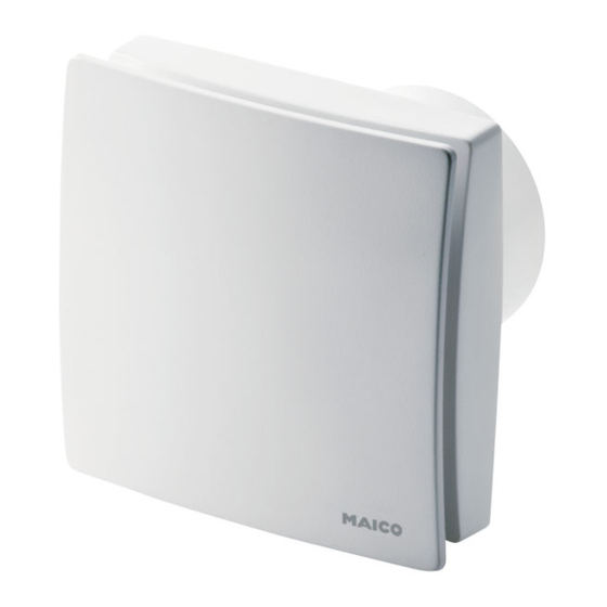
- Page 1 Instructions de montage et Mode d’emploi Aérateurs pour petites pièces ECA 100 ipro RC ECA 100 ipro RCH w w w . m a i c o - v e n t i l a t o r e n . c o m...
- Page 2 Anschluss an einem Master- Connection on a master fan Connexion sur un aérateur Ventilator ECA 100 ipro RC ECA 100 ipro RC or ECA maître ECA 100 ipro RC ou oder ECA 100 ipro RCH 100 ipro RCH ECA 100 ipro RCH ●...
-
Page 4: Table Of Contents
ECA 100 ipro RC Inhaltsverzeichnis 1. Lieferumfang ..........3 7. Montagevorbereitungen ......8 1.1 Ventilator ECA 100 ipro RC ....3 8. Montage ........... 9 1.2 Ventilator ECA 100 ipro RCH .... 3 8.1 Gehäuseeinbau ......... 9 1.3 Funkschalter DS RC......3 8.2 Elektrischer Anschluss ...... -
Page 5: Lieferumfang
Fensterkontakten. Diese besitzen eine elektrotechnische Aus- bildung und das Wissen über die Gefahren und Auswirkungen, die durch einen elektri- 1.1 Ventilator ECA 100 ipro RC schen Schlag erfolgen können. Art.-Nr. 0084.0210 ● Ventilator ECA 100 ipro RC 2.2 Verwendete Symbole ●... -
Page 6: Bestimmungsgemäße Verwendung
● wenn auf der Ausblasseite ein Berüh- ECA 100 ipro RCH rungsschutz des Flügelrades nach Ausführung wie ECA 100 ipro RC, zusätzlich EN ISO 13857 fehlt. mit Feuchte-Vollautomatik. Schalter und Steuerungskomponenten nicht Normalerweise läuft der Ventilator im Stan- im Bereich der Dusche anbringen ‒... -
Page 7: Weitere Funkkomponenten
Diese Feuchte wird als erster Referenzwert Ventilator mit mehreren Funkschaltern im gespeichert. Es ist keine manuelle Vorgabe Einzelbetrieb eines Referenzwertes mehr nötig. Funktion wie zuvor beschrieben. Bis zu Sinkt die relative Feuchte direkt nach der 5 Funkschalter je Ventilator einlernbar. Installation, wird diese als neuer Referenz- Funkschalter im Master/Slave-Netzwerk wert gespeichert. -
Page 8: Umgebungsbedingungen Und Grenzen Für Den Betrieb
(Feuchteschutz). Funkbefehle weiterer Funknetz-Teilnehmer werden bis Für technische Daten Typenschild. Für zum Ausschalten des Urlaubsmodus Abmessungen und Kennlinien: Katalog, ignoriert. oder Internet (maico-ventilatoren.com). ● Servicemenü: Für Systemeinstellungen. Bemessungsspannung 230 V Netzfrequenz 50 Hz 4. Umgebungsbedingungen und Schutzart Grenzen für den Betrieb... -
Page 9: Sicherheitshinweise
6.2 Sicheres und korrektes 6. Sicherheitshinweise Verhalten für den Betrieb 6.1 Allgemein Verletzungsgefahr durch ● Lesen Sie diese Betriebsan- Gegenstände im Flügel- leitung vor Montage und Inbe- rad. Keine Gegenstände triebnahme aufmerksam durch. in das Gerät hineinstecken. ● Die Montage und der elektri- Verletzungsgefahr durch sche Anschluss ist nur durch sich drehendes Laufrad. -
Page 10: Zuluftnachströmung Innerhalb Der Wohnung
Empfehlung: Wandhülse WH 100 6.3 Zuluftnachströmung einbauen. innerhalb der Wohnung Bei rechteckigen Wanddurchbrüchen ● Die Luftführung in der Woh- Montageplatte ZM 11 verwenden. nung muss so erfolgen, dass Bei der Elektroinstallation und Geräte- montage unbedingt die einschlägigen möglichst keine Luft aus Vorschriften beachten, in Deutschland Küche, Bad und WC in die insbesondere DIN VDE 0100 mit den... -
Page 11: Montage
Kurzschlussgefahr und ACHTUNG Gerätebeschädigung. Eindringendes Wasser bei falscher Einführung der Netzleitung in das Ventilator- gehäuse oder bei nicht fachgerecht eingebauter Leitungstülle. Kappe der Leitungstülle [3] so Beigefügtes Schaumstoffband am Stutzen abschneiden, dass die Leitungs- mittig anbringen. tülle die Netzleitung dicht An ECA 100 ipro RCH unbedingt das umschließt. -
Page 12: Inbetriebnahme
Zulässige Netzzuleitung: min. 3 x 1,5 mm². Im Gerät nur Einzeladern verlegen. Dazu Mantel der Netzleitung auf einer Länge von 90 mm entfernen. Einzelne Adern auf 9 bis 10 mm abisolieren. Gehäuse [1] in Wanddurchbruch/Wand- hülse einsetzen und mit zwei Schrauben Bei Geräteausführungen RCH mitgeliefer- befestigen. -
Page 13: Funkteilnehmer Einlernen Oder Löschen
Empfänger = Ventilatoren ECA 100 ipro RC oder ECA 100 ipro RCH. Sender = Raumluftsteuerung RLS RC, Funk- schalter, Funk-Fensterkontakte, Ventilatoren ECA 100 ipro RC oder ECA 100 ipro RCH. 9.1 Programmebenen ● Erfolgt innerhalb von 60 Sekunden kein 9.2 Tipps zum Einlernen Empfang, wird das Einlernen beendet ●... -
Page 14: Master-Slave-Zuordnung
Am Empfänger (Ventilator) den Einlern- 9.3 Master-Slave-Zuordnung modus erneut aktivieren. Ein Ventilator wird automatisch zum Die rechte Wippe 3-mal innerhalb von Master, wenn das Mastergerät in den 2 Sekunden drücken. Empfangsmodus gestellt und von > Das Einlerntelegramm wird gesendet. einem Slave-Ventilator ein Einlern- telegramm empfangen wird. -
Page 15: Sender Löschen
Einlerntaste [10] am Slave-Ventilator so 9.7 Ventilator als Signalverstärker lange drücken (>1 Sekunde), bis die LED einstellen (Repeater) am Slave-Ventilator 1-mal kurz aufleuchtet. Die im Ventilator befindliche Funkelektronik > Das Einlerntelegramm wird gesendet. kann auch für eine Signalverstärkung genutzt Bei erfolgreichem Einlernen leuchtet die werden. -
Page 16: Bedienung
Master- und Slave-Ventilatoren, die den unterschiedlichen RLS RC-System- stufen zugeordnet sind. RLS RC-Programme System- System- System- System- für ECA 100 ipro RC und stufe 0 stufe 1 stufe 2 stufe 3 ECA 100 ipro RCH Master Leistungsstufe 1... -
Page 17: Demontage
Ventilator schaltet nicht ein. Ventilator reagiert nicht auf Funk-Befehle Ursache Abhilfe Ursache Abhilfe Ventilatoren sind nicht Sender aller Kom- Keine Netzsicherung korrekt eingelernt. ponenten löschen Netzspannung einschalten (Delete-Modus Laufrad blockiert. Störungsbeseitigung Kapitel 9.6). nur durch Fachkraft Sender an der zulässig! RLS RC löschen. -
Page 18: Entsorgung
Das Gerät enthält teils wiederver- wertbare Stoffe, teils Substanzen, die nicht in den Restmüll gelangen dürfen. Entsorgen Sie das Gerät nach Ablauf seiner Lebensdauer nach den in Ihrem Land geltenden Umweltrichtlinien und Vorschriften. 16. Schaltbild ECA 100 ipro RC / ECA 100 ipro RCH... - Page 19 Table of contents 7. Installation preparations ......23 1. Scope of delivery ........18 8. Mounting ..........24 1.1 ECA 100 ipro RC fan....... 18 8.1 Housinginstallation ......24 1.2 ECA 100 ipro RC fan....... 18 8.2 Electrical connection ......24 1.3 DS RC radio switch ......
-
Page 20: Scope Of Delivery
They are trained in electrical engineering and are aware of the risks and consequences of 1.1 ECA 100 ipro RC fan an electric shock. Article no. 0084.0210 ● ECA 100 ipro RC fan 2.2 Symbols used ●... -
Page 21: Intended Use
● a surface installation on walls, ceilings RCH unit models. or ducts. ● All the ECA 100 ipro RC/RCH models in the ● an air supply via shaft or duct. network can be combined with each other. ● a permanent electrical connection, ●... -
Page 22: Further Radio Components
This humidity is saved as the first reference Fan with several radio switches in value. No further manual setting of a refe- individual operation rence value is necessary. Function as described above. Up to 5 radio If the relative humidity drops directly following switches can be set up per fan. -
Page 23: Environmental Conditions And Operating Limits
For technical data, rating plate. For dimen- from further radio network devices are sions and characteristic curves: catalogue ignored until vacation mode is switched off. or Internet (maico-ventilatoren.com). ● Service menu: For system settings. Rated voltage 230 V... -
Page 24: Safety Instructions
6.2 Safe and correct practices 6. Safety instructions during operation 6.1 General Danger of injury from ● Read these operating objects in the impeller. instructions carefully before Do not insert any objects mounting and commissioning. in the unit. ● Assembly and electrical con- Danger of injury from nection may only be under- rotating impeller. -
Page 25: Supply Air Intake Within The Living Area
Always note the relevant specifica- 6.3 Supply air intake within tions for electrical installations and the living area when installing equipment. In Germany particular attention must be paid to ● The domestic air supply must the DIN VDE 0100 and the be set up so that virtually no corresponding parts. -
Page 26: Mounting
Danger of short-circuits and NOTICE damage to the unit. Water will penetrate if the power cable is incorrectly fed into the fan housing or if the cable grom- met is not fitted correctly. Cut off cable grommet cap [3] such that the cable grommet fits tightly round the power cable. -
Page 27: Commissioning
Only lay single cable cores in the unit. To do this, remove power cable sheathing over a length of 90 mm. Strip single cable cores to 9 to 10 mm. Insert housing [1] into wall breakthrough/ wall sleeve and secure with two screws. Do not insert the housing such that it is twisted or crushed. -
Page 28: Setting Up Or Deleting Radio Devices
9. Teaching-in or deleting radio devices Receiver = ECA 100 ipro RC or ECA 100 ipro RCH fans Transmitter = RLS RC room air control, radio switches, radio window contacts, ECA 100 ipro RC or ECA 100 ipro RCH fans. -
Page 29: Master-Slave Assignment
Re-activate teach-in mode at the receiver 9.3 Master-slave assignment (fan). A fan automatically becomes a Press the right-hand rocker 3 times within master fan if the master unit is set to 2 seconds receive mode and a teach-in telegram > The teach-in telegram is sent. is received from a slave unit. -
Page 30: Deleting Transmitters
Press and hold the teach-in button [10] at 9.7 Setting up the fan as a signal the fan (>1 second), until the LED on the amplifier (Repeater) slave fan lights up briefly once. The radio electronics in the fan can also be >... -
Page 31: Operation
● Repairs should only be carried out by a For manual operation via radio trained electrician. components, ECA 100 ipro RC. Danger to life. Unit is powered up. Switch off at the mains fuse before starting work 11. -
Page 32: Dismantling
Fan does not switch on. Fan doesn't react to radio commands Cause Remedy Cause Remedy Fans are not correctly Delete all component No mains voltage. Switch the mains set up. transmitters (Delete fuse on. mode Chapter 9.6). Impeller blocked. Fault rectification Delete the transmitter may only be carried... -
Page 33: Disposal
15. Disposal 16. Wiring diagram Not in domestic waste. ECA 100 ipro RC / ECA 100 ipro RCH The unit contains, in part, material that can be recycled and, in part, substances that should not end up as domestic waste. - Page 34 ECA 100 ipro RC Sommaire 1. Volume de fourniture ......33 7. Préparatifs de montage ......38 1.1 Aérateur ECA 100 ipro RC ....33 8. Montage ..........39 1.2 Aérateur ECA 100 ipro RCH.... 33 8.1 Montage duboîtier ......39 1.3 Interrupteur radio DS RC ....
-
Page 35: Volume De Fourniture
à fournir par le client. qualifiés. Les installateurs doivent avoir une formation électrotechnique et connaître les 1.1 Aérateur ECA 100 ipro RC dangers et les effets d'un choc électrique. N° de réf. 0084.0210 ● Aérateur ECA 100 ipro RC 2.2 Symboles utilisés... -
Page 36: Utilisation Conforme
ECA 100 ipro dans les versions ● Installation apparente au mur, plafond RC et RCH. ou gaine ronde. ● Toutes les versions ECA 100 ipro RC/RCH ● Circulation de l'air par gaine rectan- en réseau sont combinables entre elles. gulaire ou ronde. -
Page 37: Autres Composants Radio
ECA 100 ipro RCH 3.5 Autres composants radio Version ECA 100 ipro RC avec contrôleur Interrupteur radio DS RC 3.5.1 d'humidité automatique en supplément. (Interrupteur EnOcean) Normalement, l'aérateur fonctionne en mode Aérateur avec interrupteur radio en mode Standard avec un niveau de puissance réglé... -
Page 38: Conditions Ambiantes Et Limites D'utilisation
Contact de fenêtre radio (protection contre l'humidité). Les ordres 3.5.2 radio d'autres parties prenantes au réseau (Interrupteur EnOcean) radio sont ignorés jusqu'à l'arrêt du mode ● Chaque aérateur possède au maximum Vacances. 2 contacts de fenêtres radio initialisables ● Menu contextuel : pour les réglages du (apprentissage). -
Page 39: Caractéristiques Techniques
électrique permanente avec Plaque signalétique. Pour les dimensions et des câbles de type NYM-O ou courbes caractéristiques consulter Cata- logue ou Internet (maico-ventilatoren.com). NYM-J (3 x 1,5 mm² ou 5 x 1,5 mm²). Prévoir un dispositif Tension de service... -
Page 40: Arrivée D'air À L'intérieur Du Logement
Risque de blessure par 6.3 Arrivée d'air à l'intérieur rotation de la turbine ! Ne du logement pas s'approcher trop près ● La circulation de l'air à de l'appareil afin d'éviter l'intérieur du logement doit que les cheveux, les être réalisée de telle manière vêtements ou les bijoux que l'air en provenance de la ne soient happés. -
Page 41: Montage
Recommandation : utiliser une gaine Déballer l'ECA et retirer le cache de pro- murale WH 100. tection [6]. Pour détacher le cache de protection, déverrouiller les crochets Pour les perçages de cloison rectan- d'arrêt ( flèche, voir Fig. ci-dessus) gulaires, utiliser une plaque de mon- avec un tournevis. -
Page 42: Branchement Électrique
Risque de court-circuit et Lors de l'installation électrique et du ATTENTION d'endommagement de l'ap- montage de l'appareil, respecter pareil ! Risque de pénétration impérativement les directives d'eau en cas d'insertion applicables et, pour l'Allemagne, plus incorrecte du câble secteur particulièrement la norme DIN VDE dans le boîtier de l'aérateur 0100 et les parties correspondantes. -
Page 43: Mise En Service
8.3 Mise en service Fonctionnement avec aérateur individuel (mode de fonctionnement individuel). Activer le fusible secteur. Sur l'aérateur, initialiser en premier lieu la commande d'air ambiant RLS RC, puis les interrupteurs radio et/ou les contacts de fenêtres radio conformément au chap. 9. Initialiser les autres composants du système. -
Page 44: Initialisation Ou Effacement Des Parties Prenantes Au Réseau Radio
9. Initialisation ou effacement des parties prenantes au réseau radio Récepteurs = aérateurs ECA 100 ipro RC ou ECA 100 ipro RCH. Émetteurs = commande d'air ambiant RLS RC, interrupteurs radio, contacts de fenêtres radio, aérateurs ECA 100 ipro RC ou ECA 100 ipro RCH. -
Page 45: Affectation Maître - Esclave
> Le télégramme d'initialisation est 9.3 Affectation maître – esclave envoyé. Une initialisation réussie est Un aérateur devient automatiquement signalée par l'allumage de la LED maître lorsque l'appareil maître placé pendant env. 1 seconde. L'échec de en mode de réception reçoit un la transmission est signalé... -
Page 46: Effacement D'émetteurs
Initialisation de l'aérateur esclave Effacement de tous les émetteurs Activer le mode Initialisation sur le Activer le mode Initialisation sur l'aérateur. récepteur maître et sur un aérateur qui n'a > La LED clignote, le mode Initialisation pas encore été initialisé (esclave prévu). est activé. -
Page 47: Utilisation
RLS RC. Programmes RLS RC Niveau Niveau Niveau Niveau pour ECA 100 ipro RC et système 0 système 1 système 2 système 3 ECA 100 ipro RCH Maître Arrêt... -
Page 48: Entretien
L'aérateur ne se met pas en marche. Pour la commande manuelle par composant radio ECA 100 ipro RC. Cause Remède Pas de tension du Activer le fusible secteur. -
Page 49: Démontage
Répéteur [Repeater] sur un aérateur situé 16. Schéma de branchement à proximité. En cas de portée trop ECA 100 ipro RC / ECA 100 ipro RCH réduite, utiliser un répéteur [Repeater] supplémentaire (sur site). 14. Démontage Danger de mort par électro- cution ! Seul un électricien qualifié... - Page 50 Maico Elektroapparate-Fabrik GmbH • Steinbeisstr. 20 • 78056 Villingen-Schwenningen • Germany • Service +49 7720 694 447 • technik@maico.de...
Need help?
Do you have a question about the ECA 100 ipro RC and is the answer not in the manual?
Questions and answers