
Related Manuals for Viavi SmartClass OLP-85 Series


Summary of Contents for Viavi SmartClass OLP-85 Series
- Page 1 OLP-85/OLP-85P SmartClass™ Fiber Optical Power Meters Operating manual BN 2307/98.21 2020.04 English...
- Page 2 430 N. McCarthy Blvd. • Milpitas, CA 95035 USA Copyright © Copyright 2019 Viavi Solutions Inc. All rights reserved. Viavi and the Viavi logo are trademarks of Viavi Solutions Inc. All other trademarks and registered trademarks are the properties of their respective owners.
-
Page 3: Table Of Contents
ONTENTS ONTENTS ......6 NTRODUCTION OLP-85/OLP-85P Power Meters ..... . 6 Operating manual update . - Page 4 ONTENTS ..45 EASURING OSS WITH OURCE OWERMETER General information ....... 45 Performing the measurement .
- Page 5 OMPLIANCE Viavi Environmental Management Program ..80 EU WEEE and Battery Directives ..... 81 EU REACH .
-
Page 6: Introduction
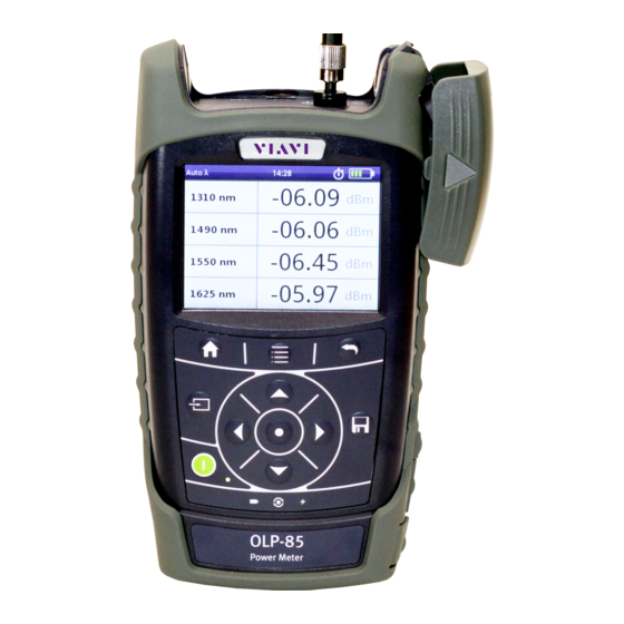
NTRODUCTION OLP-85/OLP-85P P OWER ETERS NTRODUCTION OLP-85/OLP-85P Power Meters This manual applies to the models BN 2307/03 and BN 2308/03. The SmartClass™ Fiber OLP-85 power meters are professional, compact handheld test instruments designed for testing, installing, and maintaining single-mode and multi-mode cables and networks. -
Page 7: Operating Manual Update
If the operating instructions about features provided by your instrument are missing, please visit the Viavi web site to check if additional information is available. To download the latest user manual: Visit the Viavi web site at http://updatemyunit.net. -
Page 8: Symbols Used In This Operating Manual
NTRODUCTION YMBOLS USED IN THIS OPERATING MANUAL Symbols used in this operating manual Various elements are used in this operating manual to draw attention to special meanings or important points in the text. Symbols and terms used in warnings The following warnings, symbols and terms are used in this document in compliance with the American National Standard ANSI Z535.6-2011: NOTICE... - Page 9 NTRODUCTION YMBOLS USED IN THIS OPERATING MANUAL The following elements are used in this operating manual: Requirement This requirement must be met first; e.g. The system is switched on. Instruction Follow the instructions given (the numbers indicate the order in which the instructions should be followed); e.g. Select mode.
-
Page 10: Safety Information
AFETY NFORMATION ARNING SYMBOLS ON THE UNIT AFETY NFORMATION Warning symbols on the unit Warning symbols indicating a potential hazard In all cases where the unit is labeled with a warning symbol, the operating manual must be consulted to learn more about the nature of the potential hazard and any action that must be taken. -
Page 11: Laser Safety
AFETY NFORMATION ASER SAFETY Laser safety WARNING Dangerous laser radiation Laser radiation can cause irreparable damage to eyes and skin. The maximum permitted power for the OLP-85 means that the optical input signals can reach hazard level. Bear this in mind when using the OLP-85. Always be aware of the hazard level of the instrument to be connected. -
Page 12: Ventilation
AFETY NFORMATION ENTILATION Ventilation NOTICE Insufficient ventilation Insufficient ventilation can damage the instrument or adversely affect its function and safety. Ensure adequate ventilation when operating the instrument. PS4 Universal AC/DC Power Supply Safety class The PS4 Universal AC/DC Power Supply unit has a protective isolation that conforms with IEC 60950. - Page 13 AFETY NFORMATION PS4 U AC/DC P NIVERSAL OWER UPPLY NOTICE Condensation Operation in the presence of condensation can damage the PS4 Universal AC/DC Power Supply or adversely affect its function and safety. Do not operate the PS4 Universal AC/DC Power Supply if condensation has formed.
-
Page 14: Getting Started
This is particularly likely if the packaging is visibly damaged. If there is damage, do not attempt to operate the instrument. Doing so can cause further damage. In case of damage, please contact your local Viavi sales company. Addresses can be found at www.viavisolutions.com. - Page 15 ETTING TARTED NPACKING THE INSTRUMENT Instrument overview Fig. 1 Front view OLP-85 Patch cord microscope (PCM) PCM controls: focus control, automated Pass/Fail analysis, magnification control Connector interface Test head cover 3.5 inch touchscreen Key pad (operator control panel) Battery compartment and stand (on rear of instrument) USB 2.0 device port (Type Micro-B) USB 2.0 host port (Type A) and external power supply connector Ethernet port (RJ-45)
- Page 16 ETTING TARTED NPACKING THE INSTRUMENT Connector panel Fig. 2 Connector panel with FC adapter (example) Optical connector Fig. 3 External power supply connector and communication inter- faces Ethernet port (RJ-45) External power supply connector USB 2.0 host port (Type A) USB 2.0 device port (Type Micro-B) OLP-85/OLP-85P...
- Page 17 ETTING TARTED NPACKING THE INSTRUMENT Power supply The following power sources can be used to operate the OLP-85: • Eight 1.5 V dry batteries (Mignon AA size, alkaline type recommended) • Eight 1.2 V NiMH rechargeable batteries (Mignon AA size, no internal charge) •...
- Page 18 ETTING TARTED NPACKING THE INSTRUMENT Replacing batteries Fig. 4 Replacing the batteries RBP2 Li-Ion Battery Pack Latch lock AA battery tray The battery compartment is on the back of the instrument. Press down the latch to release and to open the lid of the battery compartment.
- Page 19 ETTING TARTED NPACKING THE INSTRUMENT NOTE: Rechargeable AA batteries will not be recharged in the instrument. For AA-type rechargeable batteries please use an external charger. It is not possible to charge the rechargeable AA batteries or the RBP2 Li-Ion Battery Pack via the USB interface. If the PS4 Universal AC/DC Power Supply and the USB interface are both connected, the instrument is powered by the PS4 Universal AC/DC Power Supply.
- Page 20 You will often be able to return used batteries to the place where you purchase new ones. Any dry or rechargeable batteries that you purchased from Viavi can be returned to one of our Service Centers for disposal. Operation from AC power...
- Page 21 ETTING TARTED NPACKING THE INSTRUMENT Fig. 5 PS4 Universal AC/DC Power Supply To change the AC line plug adapter: Squeeze both sides of the PS4 latch lock (see Fig. Push the AC line plug adapter upwards. Slide a different AC line plug adapter into the slot (see Fig.
-
Page 22: Connecting Optical Cables
(UPP) for all types of 2.5 mm connectors (UPP adapter for 1.25 mm ferrules are also available). It is suitable for connectors with planar (PC) and angled end surfaces (APC). Contact your local Viavi sales company for the 1.25 mm UPP adapter. OLP-85/OLP-85P... -
Page 23: Basic Operation
ASIC PERATION WITCHING THE INSTRUMENT ON ASIC PERATION Switching the instrument on/off To switch the instrument on: Press the key to switch on the instrument. To switch the instrument off : Press the key to shift the instrument into hibernate mode. –... -
Page 24: Menus And Display Elements
ASIC PERATION ENUS AND DISPLAY ELEMENTS Menus and display elements Home screen Fig. 7 Home screens: Test applications (screen shows PCM version) (1), Management (2), Settings (3) Menu See page Test applications In this menu you can open test applications. Management In this menu you can: •... - Page 25 ASIC PERATION ENUS AND DISPLAY ELEMENTS Test applications Fig. 8 Test applications (screen shows PCM version) Application See page Powermeter To install and maintain cables and networks with the broadband power meter. Probe To view and inspect the bulkhead (female) connectors. PCM (Patch Cord Microscope) (only BN 2326) To view and inspect the patch cord connector of the fiber.
- Page 26 ASIC PERATION ENUS AND DISPLAY ELEMENTS Elements in the top bar Project title Indicates the title of the active project WIFI Indicates that Wifi is installed. It does not indicate an active Wifi connection. Bluetooth Indicates that Bluetooth is installed. It does not indicate an active bluetooth connection.
-
Page 27: Navigating In The Menus
ASIC PERATION AVIGATING IN THE MENUS Navigating in the menus Press the key to open the home screen. Depending on the active project type the Projects tab shows the available test applications or the active Workflow project. Press the key to open the context-sensitive menu. Depending on which application is selected, a different menu opens. -
Page 28: Changing System Settings
ASIC PERATION HANGING YSTEM ETTINGS Changing System Settings In the Settings menu you can change instrument settings, get information and help about the instrument, or update the firmware. To open the Settings menu: The home screen is displayed. Select the tab. - Page 29 ASIC PERATION HANGING YSTEM ETTINGS Icon Function See page WiFi To configure the wireless local area network. The last selected item is displayed in magenta. Bluetooth To configure the Bluetooth interface. Brightness To adjust the display brightness. Help To show device information SW Options Not yet available,...
- Page 30 ASIC PERATION HANGING YSTEM ETTINGS Setting the [Screen-Off interval When [Screen-Off] is set, the display will switch off after the selected interval without any user action. NOTE: [Screen-Off] is only active when no external power supply is connected. In the menu tap the [More] button,...
- Page 31 ASIC PERATION HANGING YSTEM ETTINGS To set 24-hour or 12-hour time: Tap [Time Format]. Select the desired time format. Setting the Ethernet protocol In the menu tap the [More] button, then tap [Ethernet]. To select the IP mode: Tap the [IP Mode] button.
-
Page 32: Wifi Menu (Optional)
ASIC PERATION I MENU OPTIONAL In the menu tap the [More] button, then tap [Factory Reset]. [Yes] to proceed. – or – [No] to cancel. WiFi menu (optional) In the menu tap the [WiFi] button. Editable settings are displayed – Enabled: switch WiFi on/off –... -
Page 33: Updating The Firmware
The latest version of the firmware can be downloaded from the Internet. To find the latest firmware version: Visit the Viavi web site at http://updatemyunit.net. Select your model from the product line. Open the download area and download the latest firmware. - Page 34 ASIC PERATION REATING SCREENSHOTS Set the Add Auto-Increment Number function ON or OFF. If the setting is ON, a number is added to the proposed name, ascending each time that a new screenshot is taken. Edit the Auto-Increment Number field by tapping the pencil button if you want to change the current number.
-
Page 35: Managing Projects
ANAGING ROJECTS REATING A NEW PROJECT ANAGING ROJECTS Stored Measurements are assigned to a project. Therefore a project first has to be created and set to active. As factory setting one Test-Tool project named default is available, which can be edited but not deleted. -
Page 36: Editing A Project
ANAGING ROJECTS DITING A PROJECT Adding a new project: Press the key. The edit menu opens. Tap [Add]. The title edit menu opens. Type in the project title and tap The project is created and displayed in the list. Copying an existing project: Select the project you wish to copy. -
Page 37: Deleting A Project
ANAGING ROJECTS ELETING A PROJECT Edit the fields. The changes are immediately effective. Press the button to close the edit menu. Deleting a project Select the project you wish to delete. Press the key and tap [Remove]. [Yes] to permanently delete the project. The project is deleted and removed from the list. -
Page 38: Powermeter Operation
OWERMETER PERATION ENERAL INFORMATION OWERMETER PERATION General information This chapter describes how to use the OLP-85/OLP-85P as a power meter. In Powermeter mode up to two wavelengths can measured simultaneously. Results can be displayed as absolute level in dBm/Watt, relatively to a reference value in dB or as Pass/ Fail indication based on predefined limits. - Page 39 OWERMETER PERATION ETTING AND SELECTING WAVELENGTHS Fig. 12 Measurement display (screen shows the settings menu) Creating and editing wavelengths in the table In the [Edit menu wavelengths can be added and Table] deleted. Furthermore for each wavelength the reference value and the limit can be defined.
- Page 40 OWERMETER PERATION ETTING AND SELECTING WAVELENGTHS To delete a wavelength: The Edit Table menu in Powermeter mode is displayed. Select the desired wavelength. Press the key and tap the [Delete button. To edit the reference value: The Edit Table menu in Powermeter mode is displayed. Select the desired wavelength.
- Page 41 PERATION ETTING AND SELECTING WAVELENGTHS Enabling Auto- mode Auto is a special feature developed by Viavi that allows you to identify wavelengths automatically (from OLS-XX, MTS-2k/4k/6k OTDR CW-source). To do this, the signal is modulated at a certain frequency (by a light source equipped with Auto , such as a Viavi OLS-85), which can be detected by a Viavi OLP-85.
-
Page 42: Selecting And Changing The Power Display Mode
OWERMETER PERATION ELECTING AND CHANGING THE POWER DISPLAY MODE Selecting and changing the power display mode The OLP-85/OLP-85P provides following display modes: • absolute power level in dBm or Watt • power level in dB relatively to a reference value •... -
Page 43: Saving Powermeter Test Results
OWERMETER PERATION AVING OWERMETER TEST RESULTS To set the actual power level as reference level: The instrument is in Powermeter mode. Press the key and tap the [Store ABS > REF] button. The actual power level is set as the new reference level. The reference level is displayed underneath the wavelength. - Page 44 OWERMETER PERATION AVING OWERMETER TEST RESULTS Defined label name. Tap field to edit label name. • Probe: Number of already saved probe results. • Powermeter: Number of already saved powermeter results. • PCM: Number of already saved PCM results. Decrease / increase label ID Save results To edit the label name, tap the field, edit the name and tap [OK].
-
Page 45: Easuring Oss With Ource Owermeter
EASURING OSS WITH OURCE OWERMETER ENERAL INFORMATION EASURING OSS WITH OURCE OWERMETER General information The OLP-85 offers three different measurement modes. • Source Mode: The instrument works as a laser source. • Powermeter Mode: The instrument works as an optical power meter. -
Page 46: Viewing Test Results
EASURING OSS WITH OURCE OWERMETER IEWING TEST RESULTS Fig. 13 Performing the measurement (for both directions by switching source and powermeter mode) Connection Laser source output (Transmitter) Powermeter input (Receiver) Source device Powermeter device Fiber system under test Viewing test results The measured loss is displayed in real time. -
Page 47: Saving Loss Test Results
EASURING OSS WITH OURCE OWERMETER AVING OSS TEST RESULTS Fig. 15 Result overview over two wavelengths Saving Loss test results Before starting a measurement a project must be selected and set to active. Thus, all results are assigned to that project when saved. - Page 48 EASURING OSS WITH OURCE OWERMETER AVING OSS TEST RESULTS Defined label name. Tap field to edit label name. • Probe: Number of already saved probe results. • Powermeter: Number of already saved powermeter results. • PCM: Number of already saved PCM results. Decrease / increase label ID Save results To edit the label name, tap the field, edit the name and tap...
-
Page 49: Probe /Pcm Operation
/PCM O ROBE PERATION ENERAL INFORMATION /PCM O ROBE PERATION General information Dirty and/or damaged connectors are often the root cause of optical network problems. The Probe and PCM applications enable industry standard inspection and automated Pass/Fail testing with report generation of optical connectors/adapters in order to ensure industry standard fiber endface quality and cleanliness. -
Page 50: Fmae Series Adapters For The Pcm
/PCM O ROBE PERATION FMAE SERIES ADAPTERS FOR THE Fig. 16 Patch cord microscope components FMAE adapter QuickCapture™ key Focus Control Magnification Control key FMAE series adapters for the PCM SmartClass™ Fiber devices with the PCM use FMAE series adapters to ensure consistent and accurate inspection for a wide variety connectors and applications. - Page 51 /PCM O ROBE PERATION P5000 EATURES AVAILABLE WITH THE IGITAL ROBE provides fast toggling between two microscope magnification levels - low magnification for high level inspection of the fiber endface and high magnification for detailed inspection of the fiber endface. The P5000i Digital Probe kit sold with the OLP-85 contains the standard barrel assembly (FBPP-BAP1), standard patch cord tips, and standard bulkhead tips.
-
Page 52: Quickcapture™ Key
/PCM O ROBE PERATION ™ UICK APTURE Fig. 18 FBPT series tips for the P5000i Inspection tip Barrel assembly P5000i connection The Probe application requires a P5000i Digital Probe in order to be fully functional (see the list of all accessories in “Digital Analysis Microscope”... -
Page 53: File Toolbar
/PCM O ROBE PERATION ILE TOOLBAR NOTE: Use the Focus Control key to adjust the focus of the image. The Digital Probe is connected to the instrument. To display the live view, tap the [Probe] button. File toolbar Saving a picture It is possible to save the frozen picture from the Digital Probe. - Page 54 /PCM O ROBE PERATION ONFIGURING THE IGITAL ROBE To launch the test with the predefined profile (see “Profile” on page 56): With the P5000i Digital Probe, use the Focus Control key (see Fig. 17) to adjust the image quality and sharpness. Press the key and tap the [Test]...
- Page 55 /PCM O ROBE PERATION ONFIGURING THE IGITAL ROBE NOTE: To return to a Live image, press the QuickCapture™ key or press key and tap the [Live] button to view both the live image and a test result simultaneously. If the test has been passed, the image has a green colored frame. If failed, the frame is red.
- Page 56 /PCM O ROBE PERATION ONFIGURING THE IGITAL ROBE Click on the key to save a JPG file of the test result in the currently active group on the OLP-85. On the edition keypad, enter the name of the JPG file. Press Enter to validate and save the document.
-
Page 57: Saving Probe/Pcm Results
/PCM O ROBE PERATION /PCM AVING ROBE RESULTS Press the key. Tap the [Tip] button. Select the tip set on the Digital Probe to connect fiber for inspection and tap on the tip set. More Press the key. Tap the [More] button to view or change the storage location, settings and information of the Digital Probe. - Page 58 /PCM O ROBE PERATION /PCM AVING ROBE RESULTS Select the desired overlay mode. Press the key. In live view this action triggers the snapshot. As file name the label prefix defined in the project settings is showed on top of the display. To edit the file name, tap the name, edit it and tap [OK].
-
Page 59: Data Management
ANAGEMENT AVING RESULTS ANAGEMENT NOTE: Results are always stored under the currently selected (active) project. Thus, to display stored results the desired project must be set to active first (see “Managing Projects” on page 35). Saving results Saving results is explained in the descriptions of each application. - Page 60 ANAGEMENT ATA MANAGEMENT OF OWERMETER TESTS Measurement Data of Powermeter Test Fiber ID Test label name [nm] Wavelength Pow [dBm] Pow [Watt] measured Powermeter value Pow [dB] Ref [dBm] Reference value Pass/Fail Passed/failed label Limit [dBm] Limit value mode Auto optional Auto ...
- Page 61 ANAGEMENT ATA MANAGEMENT OF OWERMETER TESTS Fig. 21 Powermeter test results Press the key and tap the [Next] [Previous] button to display other results. To sort the test results: The measurement data overview is displayed. Press the key. Tap the [More] button, then tap the [Sort Order]...
-
Page 62: Data Management Of Probe And Pcm Tests
ANAGEMENT ATA MANAGEMENT OF ROBE AND TESTS Data management of Probe and PCM tests Recalling stored test results Stored test results are displayed directly from the menu in the Probe/PCM application. The Probe or PCM application is selected. Press the key. - Page 63 ANAGEMENT ATA MANAGEMENT OF ROBE AND TESTS To select one test: To select a test, tap it twice. – or – Press the arrow keys to highlight the test and press the center The check mark shows the selected test. To select multiple tests: Repeat step 1 to select multiple entries.
- Page 64 ANAGEMENT ATA MANAGEMENT OF ROBE AND TESTS To view the previous test result: The selected test result is displayed in full screen. Press the key and tap the [Prev] button. Sorting test results The measurement data overview is displayed. Press the key.
-
Page 65: Exporting Results To Usb
Smart Reporter. Making a report In order to make a report, please download the FiberChekPRO™ or SmartReporter software from the Viavi web site http://updatemyunit.net. Connect your instrument to your PC via the USB port and follow the instructions on the screen. -
Page 66: Maintenance
10 M AINTENANCE LEANING THE TEST PORT AINTENANCE WARNING Dangerous voltage and invisible laser radiation Maintenance or cleaning of the instrument while it is connected or operating may damage the instrument or injure you. Make sure that the instrument is switched off and disconnected from all power sources and optical radiation sources before maintenance or cleaning. -
Page 67: Appendix - Referencing Methods
11 A PPENDIX EFERENCING ETHODS EMOTE EFERENCING PPENDIX EFERENCING ETHODS For a fiber loss measurement per length, connection, and splice, the technician must indicate the fiber length, the number of connections, and how many splices are present in the fiber system under test. - Page 68 11 A PPENDIX EFERENCING ETHODS EMOTE EFERENCING Fig. 22 One jumper reference - unidirectional Fig. 23 One jumper reference - bidirectional (switching source and powermeter mode) Connection 1 Connection 4 Laser source output (Transmitter) Powermeter input (Receiver) Source device Powermeter device Measured loss = Δ...
- Page 69 11 A PPENDIX EFERENCING ETHODS EMOTE EFERENCING Two jumper cable reference This reference removes the losses at Connection 1, Connection 2, and Connection 4 from the measurement. Fig. 24 Two jumper reference - unidirectional Fig. 25 Two jumper reference - bidirectional (switching source and powermeter mode) Connection 1 Connection 4...
- Page 70 11 A PPENDIX EFERENCING ETHODS EMOTE EFERENCING This reference removes any loss at the connection between the transmitter of the instrument in source mode and a reference test jumper plus the loss at one connection plus a second reference test jumper (both directions). The loss at the second connection that must be present to measure the fiber system under test will not be referenced out.
- Page 71 11 A PPENDIX EFERENCING ETHODS EMOTE EFERENCING Connection 1 Connection 4 Connection 2 Connection 3 Laser source output (Transmitter) Powermeter input (Receiver) Source device Powermeter device Δ Δ Δ Δ Δ The losses ( ) at Conn. 1 Conn. 2 Conn.
-
Page 72: Remote Control
12 R EMOTE ONTROL EMOTE EFERENCING EMOTE ONTROL Please visit the Viavi web site at http://updatemyunit.net the latest Remote Command Documentation “SCF RC Docs.exe“ (self extracting zip-file). OLP-85/OLP-85P... -
Page 73: Environmental Compliance
The authority to operate this equipment is conditioned by the requirements that no modifications be made to the equipment unless the changes or modifications are expressly approved by Viavi. NOTE: To comply with FCC RF exposure compliance requirements, a separation distance of at least 20 cm must be maintained between the antenna of this device and all persons. -
Page 74: Eu Radio Equipment Directive
13 E NVIRONMENTAL OMPLIANCE EU R ADIO QUIPMENT IRECTIVE EU Radio Equipment Directive In accordance with Article 10.8 of the EU Radio Equipment Directive 2014/53/EU, the following table provides information on the frequency bands and the maximum RF transmit power of this product for sale in the EU: Frequency range Channels used... -
Page 75: Ordering Information
14 O RDERING NFORMATION OLP-85/OLP-85P STAND ALONE UNIT RDERING NFORMATION OLP-85/OLP-85P stand alone unit OLP-85 BN 2307/03 Power meter, 800–1650 nm, -75 to +26 dBm OLP-85P BN 2308/03 Power meter with integrated patch cord microscope, 800–1650 nm, -75 to +26 dBm Included items Stand alone units •... -
Page 76: Specifications
800 nm to 1300 nm: ±0.7 dB ±25 nW 1300 nm to 1550 nm: ±0.4 dB ±5 nW > 1550 nm: ±0.7 dB ±5 nW 4) With Viavi optical light source, 800 nm to 1625 nm: level > -50 dBm OLP-85/OLP-85P... -
Page 77: General Specifications
15 S PECIFICATIONS ENERAL SPECIFICATIONS General specifications Fiber inspection Via P5000i Digital Probe with auto Pass/Fail analysis Live image 320 x 240 pixels, 8 bit gray, 10 fps Display High contrast 3.5" TFT color touchscreen Display resolution 0.01 dB / 0.001 µW Measurement units dB, dBm, W Data memory... -
Page 78: Index
NDEX NDEX Display brightness, adjusting 29 Display elements 24 AC line plug adapter 20 Display mode (Powermeter) 42 Activating Displaying modulated signals 41 project 37 Display-off, setting 30 Adjusting display brightness 29 Auto Lambda mode 41 Auto-off, setting 29 Editing project 36 Environmental Management Program Batteries... - Page 79 NDEX display-off 30 Ethernet protocol 31 Navigating in the menus 27 Shipping damage 14 Showing device Information 29 Specifications On/Off 23 General 77 Operation Switching on/off 23 Probe/PCM 38 System settings, changing 28 Operation from AC power 20 Overview 15 Test adapter, mounting 22 Test results Package contents 14...
-
Page 80: Product Regulatory Compliance
Hazardous materials Viavi avoids or uses with care any hazardous or dangerous material in the manufacturing process or the end product. If the use of a dangerous material cannot be avoided, it is identified in product documentation and clearly labeled on the product itself. -
Page 81: Eu Weee And Battery Directives
EU Waste Electrical and Electronic Equipment (WEEE) Directive, 2012/19/EU, and the EU Battery Directive, 2006/66/EC. Instructions for returning waste equipment and batteries to JDSU can be found in the WEEE section of Viavi's Standards and Policies web page (https://www.viavisolutions.com/en-us/ corporate/legal/policies-standards#sustain). -
Page 82: Rohs
RoHS OLP-85/OLP-85P... - Page 83 OLP-85/OLP-85P...
- Page 84 North America +1 844-468 4284 Viavi product specifications and descriptions in Latin America +1 954 688 5660 this document are subject to change without China +86 21 6859 5260 notice. Germany +49 7121 86 0 © 2020 Operating manual SmartClass™ Fiber Optical Power Meters OLP-85/OLP-85P...
Need help?
Do you have a question about the SmartClass OLP-85 Series and is the answer not in the manual?
Questions and answers