
Related Manuals for Viavi SmartClass OLP-88


Summary of Contents for Viavi SmartClass OLP-88
- Page 1 OLP-88/OLP-88P SmartClass™ Fiber True PON Tester Operating manual BN 2327/98.21 2019.06 English...
- Page 2 Please direct all inquiries to your local Viavi sales company. The addresses can be found at: www.viavisolutions.com/en-us/contact-sales-expert A description of additional instrument features can be found at: www.viavisolutions.com/en-us/products/network-test-and-certification Notice Every effort was made to ensure that the information in this document was accurate at the time of printing.
-
Page 3: Table Of Contents
ONTENTS ONTENTS ....... . 5 NTRODUCTION OLP-88/OLP-88P TruePON Testers ....5 Operating manual update. - Page 4 ONTENTS Changing the serial number format ....45 Saving TruePON test results ......46 /PCM O .
-
Page 5: Introduction
NTRODUCTION OLP-88/OLP-88P T PON T ESTERS NTRODUCTION OLP-88/OLP-88P TruePON Testers This manual applies to the models BN 2327/36 and BN 2328/36. The SmartClass™ Fiber OLP-88/OLP-88P/88P TruePON Tester is the first compact handheld test instrument that combines • a professional PON power meter for qualification, activation, and troubleshooting passive optical networks, •... - Page 6 NTRODUCTION OLP-88/OLP-88P T PON T ESTERS An integrated pass/fail analysis feature simplifies standard conformity testing and provides unambiguous measurement result presentation. For all G-PON systems the ONU/ONT serial number is automatically provided. G-PON systems carrying PON-ID , the OLP-88/OLP-88P/-88P performs insertion loss measurements without referencing, auto setting of pass/fail thresholds based on ODN budget class, and identification of OLT.
- Page 7 PON uplink paths at 1310 nm. The average burst power is displayed independently from the burst duty cycle (active/idle). This power meter port is calibrated at the respective center wavelength. Differences between the Viavi instruments OLP-37 OLP-87 OLP-88/...
-
Page 8: Operating Manual Update
If the operating instructions about features provided by your instrument are missing, please visit the Viavi web site to check if additional information is available. To download the latest user manual: Visit the Viavi web site at http://updatemyunit.net. -
Page 9: Symbols Used In This Operating Manual
NTRODUCTION YMBOLS USED IN THIS OPERATING MANUAL Symbols used in this operating manual Various elements are used in this operating manual to draw attention to special meanings or important points in the text. Symbols and terms used in warnings The following warnings, symbols and terms are used in this document in compliance with the American National Standard ANSI Z535.6-2011: NOTICE... - Page 10 NTRODUCTION YMBOLS USED IN THIS OPERATING MANUAL Warning format All warnings have the following format: WARNING Type and source of danger Consequences of ignoring the warning. Action needed to avoid danger. The following elements are used in this operating manual: Requirement This requirement must be met first;...
-
Page 11: Safety Information
AFETY NFORMATION ARNING SYMBOLS ON THE UNIT AFETY NFORMATION Warning symbols on the unit Warning symbols indicating a potential hazard In all cases where the unit is labeled with a warning symbol, the operating manual must be consulted to learn more about the nature of the potential hazard and any action that must be taken. -
Page 12: Laser Safety
AFETY NFORMATION ASER SAFETY Laser safety WARNING Dangerous laser radiation Laser radiation can cause irreparable damage to eyes and skin. The maximum permitted power for the OLP-88/OLP-88P means that the optical input signals can reach hazard level. Bear this in mind when using the OLP-88/OLP-88P. In particular, the instrument is equipped with a through channel that transmits all the optical radiation from the input to the output without attenuation, even when the OLP-88/OLP-88P is... -
Page 13: Battery Operation
AFETY NFORMATION ATTERY OPERATION Battery operation WARNING Explosion danger Short-circuiting the batteries can result in overheating, explosion, or ignition of the batteries and their surround- ings. Never short-circuit the battery contacts by touching both contacts simultaneously with an electrical conducting object. Only use AA size dry batteries or rechargeable batteries. - Page 14 AFETY NFORMATION PS4 U AC/DC P NIVERSAL OWER UPPLY Environmental conditions NOTICE Ambient temperature too high/low Temperatures outside the operating range of 0 to +40 °C can damage the PS4 Universal AC/DC Power Supply or adversely affect its function and safety. Only operate the PS4 Universal AC/DC Power Supply indoors.
-
Page 15: Getting Started
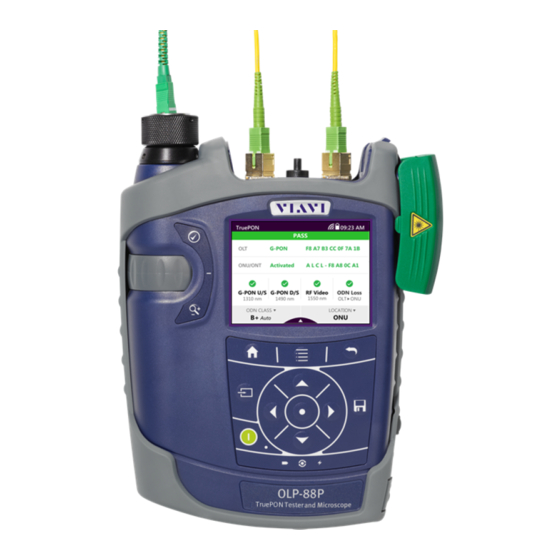
This is particularly likely if the packaging is visibly damaged. If there is damage, do not attempt to operate the instrument. Doing so can cause further damage. In case of damage, please contact your local Viavi sales company. Addresses can be found at www.viavisolutions.com. Recovery following storage/shipping Condensation can occur if a instrument that is stored or shipped at a low temperature is brought into a warm room. - Page 16 ETTING TARTED NPACKING THE INSTRUMENT Instrument overview Fig. 2 Front view OLP-88 and OLP-88P Patch cord microscope (PCM) with FMAE adapter PCM controls: focus control, automated Pass/Fail analysis, magnification control Optical test ports with interchangeable test adapters Test head cover (green for APC- and gray for PC connectors) 3.5 inch touchscreen Key pad (operator control panel) Battery compartment and stand (on rear of instrument)
- Page 17 ETTING TARTED NPACKING THE INSTRUMENT Connector panel Fig. 3 Connector panel Optical test port 1: Downstream Connection to OLT facing side of the PON Optical test port 2: Upstream Connection to ONU/ONT facing side of the PON Fig. 4 External power supply connector and communication inter- faces Ethernet port (RJ-45) External power supply connector (12 V)
- Page 18 ETTING TARTED NPACKING THE INSTRUMENT Power supply The following power sources can be used to operate the OLP-88/OLP-88P: • Eight 1.5 V dry batteries (Mignon AA size, alkaline type recommended) • Eight 1.2 V NiMH rechargeable batteries (Mignon AA size, no internal charge) •...
- Page 19 ETTING TARTED NPACKING THE INSTRUMENT Replacing batteries Fig. 5 Replacing the batteries RBP2 LiIon Battery Pack Latch lock AA battery tray The battery compartment is on the back of the instrument. Press down the latch to release and to open the lid of the battery compartment.
- Page 20 ETTING TARTED NPACKING THE INSTRUMENT NOTE: Rechargeable AA batteries will not be recharged in the instrument. For AA-type rechargeable batteries please use an external charger. It is not possible to charge the rechargeable AA batteries or the RBP2 LiIon Battery Pack via the USB interface. The instrument is powered by the PS4 Universal AC/DC Power Supply if the PS4 Universal AC/DC Power Supply and the USB interface are both connected.
- Page 21 You will often be able to return used batteries to the place where you purchase new ones. Any dry or rechargeable batteries that you purchased from Viavi can be returned to one of our Service Centers for disposal. Operation from AC power...
- Page 22 ETTING TARTED NPACKING THE INSTRUMENT Fig. 6 PS4 Universal AC/DC Power Supply To change the AC line plug adapter: Squeeze both sides of the PS4 latch lock (see Fig. Push the AC line plug adapter upwards. Slide a different AC line plug adapter into the slot (see Fig.
-
Page 23: Connecting Optical Cables
The OLP-88/OLP-88P cannot be powered via the USB interface. Connecting optical cables Mounting test adapters Viavi provides a number of test adapters for connecting the OLP-88/OLP-88P to the interface to be tested. You can connect all standard optical connector types to the instrument using these adapters. - Page 24 ETTING TARTED ONNECTING OPTICAL CABLES Fig. 8 Mounting the SENKO test adapter OLP-88/OLP-88P...
-
Page 25: Basic Operation
ASIC PERATION WITCHING THE INSTRUMENT ON ASIC PERATION Switching the instrument on/off To switch the instrument on: Press the key to switch on the instrument. To switch the instrument off: Press the key to shift the instrument into hibernate mode. –... -
Page 26: Menus And Display Elements
ASIC PERATION ENUS AND DISPLAY ELEMENTS Menus and display elements Home screen Fig. 9 Home screens: Test applications (screen shows PCM version) (1), Management (2), Settings (3) Menu See page Test applications In this menu you can open test applications. Management In this menu you can: •... - Page 27 ASIC PERATION ENUS AND DISPLAY ELEMENTS Test applications Fig. 10 Test applications (screen shows PCM version) Application See page TruePON To measure power level, identify ONT/OLT/ONUs, detect rogue ONU/ONTs and determine the total amount of loss of a fiber link. Probe To view and inspect the bulkhead (female) connectors.
- Page 28 ASIC PERATION ENUS AND DISPLAY ELEMENTS Elements in the top bar Project title Indicates the title of the active project WIFI Indicates that Wifi is installed. It does not indicate an active Wifi connection. Bluetooth Indicates that Bluetooth is installed. It does not indicate an active bluetooth connection.
-
Page 29: Navigating In The Menus
ASIC PERATION AVIGATING IN THE MENUS Navigating in the menus Press the key to open the home screen. Depending on the active project type the Projects tab shows the available test applications or the active Workflow project. Press the key to open the context-sensitive menu. Depending on which application is selected, a different menu opens. -
Page 30: Changing System Settings
ASIC PERATION HANGING YSTEM ETTINGS Changing System Settings In the Settings menu you can change instrument settings, get information and help about the instrument, or update the firmware. To open the Settings menu: The home screen is displayed. Select the tab. - Page 31 ASIC PERATION HANGING YSTEM ETTINGS Icon Function See page WiFi To configure the wireless local area network. The last selected item is displayed in magenta. Bluetooth To configure the Bluetooth interface. Brightness To adjust the display brightness. Help To show device information SW Options Not yet available,...
- Page 32 ASIC PERATION HANGING YSTEM ETTINGS Setting the [Screen-Off] interval When [Screen-Off] is set, the display will switch off after the selected interval without any user action. NOTE: [Screen-Off] is only active when no external power supply is connected. In the menu tap the [More] button,...
- Page 33 ASIC PERATION HANGING YSTEM ETTINGS To set 24-hour or 12-hour time: Tap [Time Format]. Select the desired time format. Setting the Ethernet protocol In the menu tap the [More] button, then tap [Ethernet]. To select the IP mode: Tap the [IP Mode] button.
-
Page 34: Wifi Menu (Optional)
ASIC PERATION I MENU OPTIONAL In the menu tap the [More] button, then tap [Factory Reset]. [Yes] to proceed. – or – [No] to cancel. WiFi menu (optional) In the menu tap the [WiFi] button. Editable settings are displayed – Enabled: switch WiFi on/off –... -
Page 35: Updating The Firmware
The latest version of the firmware can be downloaded from the Internet. To find the latest firmware version: Visit the Viavi web site at http://updatemyunit.net. Select your model from the product line. Open the download area and download the latest firmware. - Page 36 ASIC PERATION REATING SCREENSHOTS Set the Add Auto-Increment Number function ON or OFF. If the setting is ON, a number is added to the proposed name, ascending each time that a new screenshot is taken. Edit the Auto-Increment Number field by tapping the pencil button if you want to change the current number.
-
Page 37: Managing Projects
ANAGING PROJECTS REATING A NEW PROJECT ANAGING PROJECTS Stored Measurements are assigned to a project. Therefore a project first has to be created and set to active. As factory setting one Test-Tool project named default is available, which can be edited but not deleted. -
Page 38: Editing A Project
ANAGING PROJECTS DITING A PROJECT Adding a new project: Press the key. The edit menu opens. Tap [ADD]. The title edit menu opens. Type in the project title and tap The project is created and displayed in the list. Copying an existing project: Select the project you wish to copy. -
Page 39: Deleting A Project
ANAGING PROJECTS ELETING A PROJECT The changes are immediately effective. Press the button to close the edit menu. Deleting a project Select the project you wish to delete. Press the key and tap [Remove]. [Yes] to permanently delete the project. The project is deleted and removed from the list. -
Page 40: True Pon Operation
PON O PERATION REPARING THE MEASUREMENT PON O PERATION Preparing the TruePON measurement The homescreen is displayed. Tap the [TruePON] button. A message is displayed that no signal is detected. Connect the OLT and ONU/ONT fiber with the particular test port. -
Page 41: General View Of The Truepon Application
PON O PERATION ENERAL VIEW OF THE APPLICATION General view of the TruePON application Fig. 13 General view of the TruePON application Pass/fail summary PON-ID from OLT ONU/ONT serial number or Alien/Rogue ONT indication Pass/fail indicator of RF video signal Currently selected test location Pass/fail indicator of G-PON downstream signal Currently selected ODN budget class... - Page 42 PON O PERATION ENERAL VIEW OF THE APPLICATION To reduce workflow complexity and test the service- activation (Fig. 13-3): Since the service-activation phase is often performed by subcontractors, they must provide test reports for each turn-up. To control the service-activation reports, connect your OLP-88/ OLP-88P.
-
Page 43: Detail Views Of The Truepon Application
PON O PERATION ETAIL VIEWS OF THE APPLICATION Detail views of the TruePON application To show detailed GTC Layer results, tap the [PON] button. – or – Tap the [ONU/ONT] button. The following detailed view is displayed. Fig. 14 GTC layer detail view OLT data PON-ID Transmit Optical Level (TOL) - Page 44 PON O PERATION ETAIL VIEWS OF THE APPLICATION Fig. 15 PMD layer detail view Wavelength Measured power Margin Automatically detected or manually selected ODN budget class Upper threshold Lower threshold Fig. 16 ODN insertion loss detail view OLP-88/OLP-88P...
-
Page 45: Edit The Location/Threshold Settings
PON O PERATION DIT THE LOCATION THRESHOLD SETTINGS Edit the location/threshold settings The homescreen is displayed. Tap the [TruePON] button. Press the key. Tap the [More] button. Tap the [LOCATIONS/THRESHOLDS] button. Tap the desired test setup, press the key, and tap the [EDIT] button. -
Page 46: Saving Truepon Test Results
PON O PERATION AVING TEST RESULTS Saving TruePON test results Before starting a measurement a project must be selected and set to active. Thus, all results are assigned to that project when saved. If no project was defined by the user, the instrument will use the Test-Tool project “default”, which is always present (see “Managing projects”... - Page 47 PON O PERATION AVING TEST RESULTS NOTE: When measuring two wavelengths at a time both wavelengths are stored separately. Thus, the ID is incremented by 2. NOTE: If the label/fiber ID is not changed, the data set will be saved under the same title.
-
Page 48: Probe /Pcm Operation
/PCM O ROBE PERATION ENERAL INFORMATION /PCM O ROBE PERATION General information Dirty and/or damaged connectors are often the root cause of optical network problems. The Probe and PCM applications enable industry standard inspection and automated Pass/Fail testing with report generation of optical connectors/adapters in order to ensure industry standard fiber endface quality and cleanliness. -
Page 49: Fmae Series Adapters For The Pcm
/PCM O ROBE PERATION FMAE SERIES ADAPTERS FOR THE Fig. 17 Patch cord microscope components FMAE adapter QuickCapture™ key Focus Control Magnification Control key FMAE series adapters for the PCM SmartClass™ Fiber devices with the PCM use FMAE series adapters to ensure consistent and accurate inspection for a wide variety of connectors and applications. - Page 50 /PCM O ROBE PERATION P5000 EATURES AVAILABLE WITH THE IGITAL ROBE provides fast toggling between two microscope magnification levels - low magnification for high level inspection of the fiber endface and high magnification for detailed inspection of the fiber endface. The P5000i Digital Probe kit sold with the OLP-88/OLP-88P contains the standard barrel assembly (FBPP-BAP1), standard patch cord tips, and standard bulkhead tips.
-
Page 51: Quickcapture™ Key
/PCM O ROBE PERATION ™ UICK APTURE Fig. 19 FBPT series tips for the P5000i Inspection tip Barrel assembly P5000i connection The Probe application requires a P5000i Digital Probe in order to be fully functional (see the list of all accessories in “Accessories”... -
Page 52: File Toolbar
/PCM O ROBE PERATION ILE TOOLBAR To display the live view, tap the [Probe] button. File toolbar Saving a picture It is possible to save the frozen picture from the Digital Probe. Press the key. Edit the file name. Tap the [OK] button. - Page 53 /PCM O ROBE PERATION ONFIGURING THE IGITAL ROBE Press the key and tap the [Test] button. – or – Press the QuickCapture™ key on the Digital Probe if the button action is set to Test. When the test procedure terminates, the information shown on the display depends on the current overlay setting: Press the key and then the...
- Page 54 /PCM O ROBE PERATION ONFIGURING THE IGITAL ROBE Fig. 20 Pass/Fail analysis – overlay view Magnification Control The Magnification Control allows you to modify the live display from high to low magnification and vice-versa. In the high magnification mode, automatic centering is available. Picture selected: Live Test Allows you to launch a (new) test of the connector...
- Page 55 /PCM O ROBE PERATION ONFIGURING THE IGITAL ROBE The file is saved in the current active group directory on the OLP-88/OLP-88P. Freeze mode Once the image is acceptable (sharpness, luminosity are tuned correctly), you may freeze the picture. This feature allows you to store the resulting picture in order to compare it later to others or save it in a file.
-
Page 56: Saving Probe/Pcm Results
/PCM O ROBE PERATION /PCM AVING ROBE RESULTS More Press the key. Tap the [More] button to view or change the storage location, settings and information of the Digital Probe. Saving Probe/PCM results Images can easily be saved by pressing the key. - Page 57 /PCM O ROBE PERATION /PCM AVING ROBE RESULTS As file name the label prefix defined in the project settings is showed on top of the display. To edit the file name, tap the name, edit it and tap [OK]. To change the ID, tap [Decrement or [Increment ID].
-
Page 58: Data Management
ANAGEMENT AVING RESULTS ANAGEMENT NOTE: Results are always stored under the currently selected (active) project. Thus, to display stored results the desired project must be set to active first (see “Managing projects” on page 37). Saving results Saving results is explained in the descriptions of each application. - Page 59 ANAGEMENT ATA MANAGEMENT OF TESTS Measurement Data of TruePON Test Fiber ID Test label name Passed/failed label ONU-SN ONU Serial Number PON-ID OLT Identification Managing test results Fig. 21 Measurement data menu To select/deselect a test result: There are several ways to select and deselect test results: Tap an entry once to highlight it, tap it again to select it.
- Page 60 ANAGEMENT ATA MANAGEMENT OF TESTS Fig. 22 Detail view Power Fig. 23 Detail view Fig. 24 Detail view OLP-88/OLP-88P...
-
Page 61: Data Management Of Probe And Pcm Tests
ANAGEMENT ATA MANAGEMENT OF ROBE AND TESTS ONU/ONT Fig. 25 Detail view To delete one data set: The list of stored test results is displayed. Select one or more test results to be deleted. Press the key and tap the [Delete Selected] button. - Page 62 ANAGEMENT ATA MANAGEMENT OF ROBE AND TESTS To show all columns of the overview: Press the right/left arrow keys to show additional information. The displayed information depends on the selected application. Fiber ID Test label name Pass/Fail Passed/failed label Profile Profile label Adapter Typ of adapter...
- Page 63 ANAGEMENT ATA MANAGEMENT OF ROBE AND TESTS To select multiple tests: Repeat step 1 to select multiple entries. To select all tests: Press the key and tap [Select All]. To deselect all tests: Press the key and tap [Deselect All]. Displaying test results NOTE: When selecting multiple tests, all selected tests can be viewed...
-
Page 64: Exporting Results To Usb
ANAGEMENT XPORTING RESULTS TO Deleting stored results from a project The measurement data overview is displayed. Select one, multiple or all tests. Press the key. Tap the [Delete Selected] button. The selected test results are deleted. Actions when viewing images To toggle the image magnification low/high Press the key, then tap the... -
Page 65: Making A Report
Smart Reporter. Making a report In order to make a report, please download the FiberChekPRO™ or SmartReporter software from the Viavi web site http://updatemyunit.net. Connect your instrument to your PC via the USB port and follow the instructions on the screen. -
Page 66: Maintenance
AINTENANCE LEANING THE TEST PORT AINTENANCE WARNING Dangerous voltage and invisible laser radiation Maintenance or cleaning of the instrument while it is con- nected or operating may damage the instrument or injure you. Make sure that the instrument is switched off and disconnected from all power sources and optical radiation sources before maintenance or cleaning. -
Page 67: Remote Control
10 R EMOTE ONTROL LEANING THE INSTRUMENT EMOTE ONTROL Remote Command Documentation Please visit the Viavi web site at http://updatemyunit.net the latest Remote Command Documentation “SCF RC Docs.exe“ (self extracting zip-file). OLP-88/OLP-88P... -
Page 68: Environmental Compliance
The authority to operate this equipment is conditioned by the requirements that no modifications be made to the equipment unless the changes or modifications are expressly approved by Viavi. NOTE: To comply with FCC RF exposure compliance requirements, a separation distance of at least 20 cm must be maintained between the antenna of this device and all persons. - Page 69 11 E NVIRONMENTAL COMPLIANCE LEANING THE INSTRUMENT EU Radio Equipment Directive In accordance with Article 10.8 of the EU Radio Equipment Directive 2014/53/EU, the following table provides information on the frequency bands and the maximum RF transmit power of this product for sale in the EU: Frequency range Channels used Max.
-
Page 70: Specifications
12 S PECIFICATIONS UNCTIONALITY PECIFICATIONS Functionality General Two-port through mode Power measurements Downstream OLT signal (1490 nm) Upstream ONT signal (1310 nm burst mode) Downstream RF video signal (1550 nm) G-PON data analysis PON-ID option ODN class detection and auto threshold setting PON-ID option Power margin test with auto pass/fail analysis PON-ID option... -
Page 71: General Specifications
12 S PECIFICATIONS ENERAL SPECIFICATIONS General specifications Display High contrast 3.5" TFT color touchscreen Display resolution 0.01 dB / 0.001 µW Live image 320 x 240 pixels, 8 bit gray, 10 fps Measurement units dB, dBm, W, pass/fail >60 dB Fiber inspection (option) Via external P5000i Digital Probe Threshold sets... -
Page 72: Ps4 Universal Ac/Dc Power Supply
12 S PECIFICATIONS PS4 U AC/DC P NIVERSAL OWER UPPLY PS4 Universal AC/DC Power Supply Power supply type FW 75550/12 Nominal line voltage range 100 to 240 VAC Nominal line frequency range 47 to 63 Hz Power consumption Max. 8.5 W Output 12 V DC / 2 A Temperature range... -
Page 73: Ordering Information
13 O RDERING NFORMATION OLP-88/OLP-88P STAND ALONE UNIT RDERING NFORMATION OLP-88/OLP-88P stand alone unit OLP-88 BN 2327/36 TruePON Tester, 1310/1490/1550 nm OLP-88P BN 2328/36 TruePON Tester, 1310/1490/1550 nm, with patch cord microscope Included items Stand alon e units • SmartClass™ Fiber instrument with APC connector •... - Page 74 NDEX NDEX Device overview 16 Differences between the devices 6 AC line plug adapter 21 Display brightness, adjusting 31 Activating Display elements 26 project 39 Display-off, setting 32 Adjusting display brightness 31 Auto-off, setting 31 Editing project 38 Environmental Management Program Batteries Danger 18 Environmental protection 21...
- Page 75 NDEX Package contents 15 Test adapter, mounting 23 Packing material 15 Test results Power supply 18 managing 59 Project recalling (Loss/Length) 58 activating 39 recalling (PCM & Probe) 61 creating 37 saving (PCM & Probe) 56 deleting 39 Through path 7 editing 38 Touchscreen, calibrating 33 Projects, working with 37...
- Page 76 Hazardous materials Viavi avoids or uses with care any hazardous or dangerous material in the manufacturing process or the end product. If the use of a dangerous material cannot be avoided, it is identified in product documentation and clearly labeled on the product itself.
- Page 77 EU Waste Electrical and Electronic Equipment (WEEE) Directive, 2012/ 19/EU, and the EU Battery Directive, 2006/66/EC. Instructions for returning waste equipment and batteries to JDSU can be found in the WEEE section of Viavi's Standards and Policies web page (https://www.viavisolutions.com/en-us/ corporate/legal/policies-standards#sustain).
- Page 78 RODUCT EGULATORY OMPLIANCE OLP-88/OLP-88P...
- Page 79 North America +1 844-468 4284 Viavi product specifications and descriptions in Latin America +1 954 688 5660 this document are subject to change without China +86 21 6859 5260 notice. Germany +49 7121 86 0 © 2019 Operating manual SmartClass™ Fiber True PON Tester OLP-88/OLP-88P...
Need help?
Do you have a question about the SmartClass OLP-88 and is the answer not in the manual?
Questions and answers