
Related Manuals for Viavi SmartClass Fiber OLTS-85


Summary of Contents for Viavi SmartClass Fiber OLTS-85
- Page 1 OLTS-85 OLTS-85 SmartClass™ Fiber SmartClass™ Fiber User’s Guide User’s Guide BN 2325/98.21 BN 2325/98.21 2016.01 2016.01 English English...
- Page 2 430 N. McCarthy Blvd. • Milpitas, CA 95035 USA Copyright © Copyright 2016 Viavi Solutions Inc. All rights reserved. Viavi and the Viavi logo are trademarks of Viavi Solutions Inc. All other trademarks and registered trademarks are the properties of their respective owners.
-
Page 3: Table Of Contents
ONTENTS ONTENTS ....... . 5 NTRODUCTION OLTS-85 Loss Test Set ....... 5 OLTS-85 Light Sources . - Page 4 ONTENTS Setting the power level ......56 Switching on/off the laser ......57 /PCM O .
-
Page 5: Introduction
NTRODUCTION OLTS-85 L NTRODUCTION OLTS-85 Loss Test Set The SmartClass™ Fiber OLTS-85 (optical loss test set) contents high-performance, easy-to-use instruments with a two or four wavelength light source and a power meter. They are universal instruments for Tier 1 certification of single-mode and multi- mode fibers, installation, maintenance, and troubleshooting. -
Page 6: Olts-85 Light Sources
NTRODUCTION OLTS-85 L IGHT OURCES OLTS-85 Light Sources The SmartClass™ Fiber OLTS-85 light sources are professional, versatile, compact handheld instruments designed for qualification and certification of fiber optic networks. Carefully chosen combinations of available wavelengths make SmartClass™ Fiber OLTS-85 light sources the optimum choice for link loss testing and characterization of long-haul, metro, and access telecommunication networks, as well as for data center and local area network testing. -
Page 7: Operating Manual Update
If the operating instructions about features supported by your instrument are missing, please visit the Viavi web site to check if additional information is available. To download the latest user manual: Visit the Viavi web site at http://updatemyunit.net. -
Page 8: Symbols Used In This Operating Manual
NTRODUCTION YMBOLS USED IN THIS OPERATING MANUAL Symbols used in this operating manual Various elements are used in this operating manual to draw attention to special meanings or important points in the text. Symbols and terms used in warnings The following warnings, symbols, and terms are used in this document in compliance with the American National Standard ANSI Z535.6-2011: NOTICE... - Page 9 NTRODUCTION YMBOLS USED IN THIS OPERATING MANUAL Warning format All warnings have the following format: WARNING Type and source of danger Consequences of ignoring the warning. ► Action needed to avoid danger. The following character formats are used in this operating manual: Requirement √...
-
Page 10: Safety Information
AFETY NFORMATION ARNING SYMBOLS ON THE UNIT AFETY NFORMATION Warning symbols on the unit Warning symbols indicating a potential hazard ► In all cases where the unit is labeled with a warning symbol, the operating manual must be consulted to learn more about the nature of the potential hazard and any action that must be taken. -
Page 11: Laser Safety
AFETY NFORMATION ASER SAFETY Laser safety WARNING Dangerous laser radiation Laser radiation can cause irreparable damage to eyes and skin. This device is a Class 1 laser product according to DIN EN 60825-1:2007. ► Always be aware of the hazard level of the instrument to be connected. -
Page 12: Ventilation
AFETY NFORMATION ENTILATION Ventilation NOTICE Insufficient ventilation Insufficient ventilation can damage the instrument or adversely affect its function and safety. ► Ensure adequate ventilation when operating the instrument. PS4 Universal AC/DC Power Supply Safety class The PS4 Universal AC/DC Power Supply unit has a protective isolation that conforms with IEC 60950. - Page 13 AFETY NFORMATION PS4 U AC/DC P NIVERSAL OWER UPPLY NOTICE Condensation Operation in the presence of condensation can damage the PS4 Universal AC/DC Power Supply or adversely affect its function and safety. ► Do not operate the PS4 Universal AC/DC Power Supply if condensation has formed.
-
Page 14: Getting Started
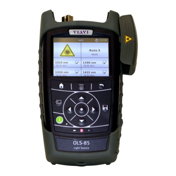
This is particularly likely if the packaging is visibly damaged. If there is damage, do not attempt to operate the instrument. Doing so can cause further damage. In case of damage, please contact your local Viavi sales company. Addresses can be found at www.viavisolutions.com. Recovery following storage/shipping Condensation can occur if an instrument that is stored or shipped at a low temperature is brought into a warm room. - Page 15 ETTING TARTED NPACKING THE INSTRUMENT Instrument overview Fig. 1 Front view OLTS-85 and OLTS-85P Patch cord microscope (PCM) with FMAE adapter PCM controls: focus control, automated Pass/Fail analysis, magnification control Connector interface Test head cover (green for APC- and gray for PC connectors) 3.5 inch touchscreen Key pad (operator control panel) Battery compartment and stand (on rear of instrument)
- Page 16 ETTING TARTED NPACKING THE INSTRUMENT Connector panel Fig. 2 Connector panel Optical connector 1, single-mode Optical connector 2, multi-mode Input port for broadband measurement Fig. 3 External power supply connector and communication interfaces Ethernet port (RJ-45) External power supply connector USB 2.0 host port (Type A) USB 2.0 device port (Type Micro-B) OLTS-85...
- Page 17 ETTING TARTED NPACKING THE INSTRUMENT Power supply The following power sources can be used to operate the OLTS-85: • Eight 1.5 V dry batteries (Mignon AA size, alkaline type recommended) • Eight 1.2 V NiMH rechargeable batteries (Mignon AA size, no internal charge) •...
- Page 18 ETTING TARTED NPACKING THE INSTRUMENT The battery compartment is on the back of the instrument. Press down the latch to release and to open the lid of the battery compartment. Insert new batteries or remove the used batteries and replace them with fresh ones.
- Page 19 You will often be able to return used batteries to the place where you purchase new ones. Any dry or rechargeable batteries that you purchased from Viavi can be returned to one of our Service Centers for disposal. OLTS-85...
- Page 20 ETTING TARTED NPACKING THE INSTRUMENT Operation with AC power NOTICE: Only the PS4 Universal AC/DC Power Supply may be used to operate the OLTS-85 with AC power. To fit the AC line plug adapter: Select the appropriate AC line plug adapter. Slide the AC line plug adapter into the slot.
-
Page 21: Connecting Optical Cables
The OLTS-85 cannot be powered via the USB interface. Connecting optical cables Mounting test adapters Viavi provides a number of test adapters for connecting the OLTS-85 to the interface to be tested. You can connect all standard optical connector types to the instrument using these adapters. - Page 22 ETTING TARTED ONNECTING OPTICAL CABLES To mount the SENKO test adapter: √ The optical connectors are properly cleaned (see “Cleaning the test port” on page 75). Open the head cover and remove the protective cap (if still mounted). Unscrew the SENKO test adapter and pull it off vertically. Place the SENKO test adapter vertically on the optical connector.
-
Page 23: Basic Operation
ASIC PERATION WITCHING THE INSTRUMENT ON ASIC PERATION Switching the instrument on/off To switch the instrument on: ► Press the [E] key to switch on the instrument. To switch the instrument off: ► Press the [E] key to shift the instrument into hibernate mode. –... -
Page 24: Display Elements
ASIC PERATION ISPLAY ELEMENTS Display elements Fig. 8 Homescreen Link Data Mode The saved results of any application are assigned to a dedicated project and FiberID. Auto-Off Indicates whether the instrument turns off within a certain time. External power supply The OLTS-85 is powered by the external AC adapter when this symbol is shown. -
Page 25: Navigating In The Menus
ASIC PERATION AVIGATING IN THE MENUS Navigating in the menus ► Press the [A] key to open the context-sensitive menu. Depending on which application is in the foreground, a different menu opens. To select a menu item: Press the arrow keys to highlight an item. To confirm, press the center key within the arrow keys. -
Page 26: Configuring The Instrument
ASIC PERATION ONFIGURING THE INSTRUMENT Configuring the instrument This chapter describes the configuration of the System Settings. System Settings menu overview √ The homescreen is displayed. ► Press the [A] key and tap the [Settings] button. The System Settings menu opens: The following table gives a short overview of the menu items. - Page 27 To configure the wireless local area networks. Factory Reset Set the instrument parameters and settings to their default values as defined by Viavi. This does not affect any stored measurement results. Changing the Auto-Off setting √ The instrument is switched on.
- Page 28 ASIC PERATION ONFIGURING THE INSTRUMENT Tap the language you want to select. – or – Press the arrow keys to highlight the language you want to select and to confirm press the center key within the arrow keys. Setting the date Press the [A] key and tap the [Settings] button.
- Page 29 ASIC PERATION ONFIGURING THE INSTRUMENT Setting 24-hour or 12-hour time Press the [A] key and tap the [Settings] button. Tap the [Date & Time] button. Tap the [Time Format] button. To change the setting, tap the desired time format. Selecting the IP mode Press the [A] key and tap the [Settings] button.
-
Page 30: Software Options
Date and time are reset and the stored measurement data remains. Software options To install new software options: Contact your local Viavi sales company or visit the Viavi web site at www.viavisolutions.com. Select a software option from the product line and order it just like an instrument. - Page 31 ASIC PERATION OFTWARE OPTIONS Press the [A] key and tap the [Software Options] button. The menu opens: To start the installation, tap the [Install license via USB stick] button. – or – To type the license key, tap the [Install license via key] button.
-
Page 32: Tier 1 Loss Test Operation
PERATION PERATION Tier 1 Loss Test General information The OLTS-85 offers three different measurement modes. • Source Mode: The instrument works as a laser source. • OPM Mode: The instrument works as an optical power meter. • Tier 1 Loss Test Mode: The internal laser source and powermeter are locked. - Page 33 PERATION Test setups can only be set on the local instrument. After connecting, the settings are transmitted to the remote instrument. To distinguish the instruments stick adhesive labels: Furthermore, there are adhesive labels with Local and Remote imprint, which serve to distinguish each instrument. ►...
- Page 34 PERATION Tap the [More] button. Tap the [Length Unit] button. Tap the desired length unit. To activate or deactivate the connection tone: √ The instrument is in Tier 1 Test mode. Press the [A] key. Tap the [More] button. Tap the [Enable Tone] button to activate or deactivate the connection tone.
- Page 35 PERATION Fig. 10 Loopback mode und Remote mode configuration Under Cable Manufacturer and Cable Name, the manufacturer, and used cable type is selected. This can be definied in Manage Cables (see “Changing general instrument settings” on page 32). In addition, the measuring direction can be specified. In Unidirectional, measurements are performed in only one direction.
- Page 36 PERATION – Cable Manufacturer – Cable Name – Connector: SM SC, SM LC, SM ST, MM SC, SM LC, SM ST – Direction: unidirectional, or bidirectional – Reference Method: 1 jumper, 2 jumper, or 3 jumper – Limit: TIA 568.3, ISO 11801, ISO 14763-3 –...
-
Page 37: Referencing Methods
PERATION EFERENCING METHODS To display further information, press the [A] key and tap the [View Detail] button, or tap the wavelength on the touchscreen. ► To save the results, press the [G] key. Referencing methods For referencing, please only use the special test reference cords contained as a standard assembly in your OLTS-85 test kit. - Page 38 PERATION EFERENCING METHODS One jumper reference method The dual-ended reference removes the losses at connection 1 and connection 4 from the measurement. One jumper reference for single-mode fiber Fig. 11 One jumper reference: single-mode remote and single-mode loopback For more information on performing a measurement refer to Fig.
- Page 39 PERATION EFERENCING METHODS One jumper reference for multi-mode fiber Fig. 12 One jumper reference: multi-mode remote and multi-mode loopback For more information on performing a measurement refer to Fig. Reference connector to reference connector mated loss: 0.1 dB Reference connector to random connector: ISO 14763-3: 0.3 dB, TIA 568.3/ISO 11801: 0.75 dB Random to random connector: 0.75 dB Splice loss: 0.3 dB...
- Page 40 PERATION EFERENCING METHODS Two jumper reference method The dual-ended reference removes the losses at Connection 1, Connection 2, and Connection 4 from the measurement. Two jumper reference for single-mode fiber Fig. 13 Two jumper reference: single-mode remote and single-mode loopback For more information on performing a measurement refer to Fig.
- Page 41 PERATION EFERENCING METHODS Two jumper reference for multi-mode fiber Fig. 14 Two jumper reference: multi-mode remote and multi-mode loopback For more information on performing a measurement refer to Fig. Reference connector to reference connector mated loss: 0.1 dB Reference connector to random connector: TIA 568.3/ ISO 11801: 0.75 dB (ISO 14763-3 not allowed) Random to random connector: 0.75 dB Splice loss: 0.3 dB...
- Page 42 PERATION EFERENCING METHODS Three jumper reference method The dual-ended reference removes the losses at Connection 1, Connection 2, Connection 3, and Connection 4 from the measurement. Three jumper reference for single-mode fiber Fig. 15 Three jumper reference: single-mode remote and single-mode loopback For more information on performing a measurement refer to Fig.
- Page 43 PERATION EFERENCING METHODS Three jumper reference for multi-mode fiber Fig. 16 Two jumper reference: multi-mode remote and multi-mode loopback For more information on performing a measurement refer to Fig. Reference connector to reference connector mated loss: 0.1 dB Reference connector to random connector: ISO 14763-3: 0.3 dB, TIA 568.3/ISO 11801: 0.75 dB Random to random connector: 0.75 dB Splice loss: 0.3 dB...
- Page 44 PERATION EFERENCING METHODS Example loss limit calculation • 2 connectors • 1 splice • Multi-mode • Fiber length: 842 m Settings • One jumper reference • Loss per connection: 0.45 dB • Loss per splice: 0.2 dB • Cable loss: 3.5 dB/km Limit = Length of fiber * Loss/km + L (0.3 dB) + L...
-
Page 45: Pass/Fail Indication
PERATION AIL INDICATION Pass/Fail indication Pass/Fail indication for losses is only available in Tier 1 mode. When performing fiber certification, the loss of the fiber system under test must be measured and compared to a calculated loss limit to provide a loss margin. The calculated loss limit is the maximum allowable loss of the overall system and is based on the following factors: •... -
Page 46: Powermeter Operation
OWERMETER PERATION ENERAL INFORMATION OWERMETER PERATION General information WARNING Dangerous laser radiation Laser radiation can cause irreparable damage to eyes and skin. The maximum permitted power for the OLTS-85 means that the optical input signals can reach hazard level. Bear this in mind when using the OLTS-85. ►... - Page 47 OWERMETER PERATION OWERMETER MEASUREMENT Setting a wavelength in the λ table To show or hide wavelengths in the λ table: √ The instrument is in Powermeter mode. Press the [A] key. Tap the [More] button. Tap the [Edit λ Table] button.
- Page 48 [OK] button. Enabling Auto λ mode Auto λ is a special feature developed by Viavi that allows you to identify wavelengths automatically. To do this, the signal is modulated at a certain frequency (by a light source equipped with Auto λ), which can be detected by a Viavi OLTS-85.
- Page 49 OWERMETER PERATION OWERMETER MEASUREMENT Displaying modulated signals The OLTS-85 automatically detects the modulation frequency of light signals modulated at the fixed frequencies of 270 Hz, 1 kHz, and 2 kHz. The detected frequency is shown in the lower right display pane of the Powermeter application. Changing the power display mode √...
- Page 50 OWERMETER PERATION OWERMETER MEASUREMENT To edit the reference level: √ The Powermeter screen is displayed. Press the [A] key. Tap the [More] button. Tap the [Edit λ Table] button. table is displayed. λ Tap the desired wavelength value. Press the [A] key. Tap the [Reference] button.
-
Page 51: Laser Operation
The output signals of the light sources may be either continuous wave (CW) or modulated at certain frequencies, i.e. 270 Hz, 1 kHz, or 2 kHz. Viavi power meters (e.g. OLP-3x, OLP-8x) are capable of detecting these modulation frequencies. This method... - Page 52 OLTS-85 embeds wavelength ID information into the emitted signal(s). This wavelength ID information can be utilized by a compatible Viavi power meter (e.g. OLP-85) for automatic wavelength setup and for simultaneous reception of multiple wavelengths. This minimizes test time and prevents common errors such as incorrect wavelength setting on the optical power meter.
-
Page 53: Selecting A Laser Source
When in one of the Auto λ modes, the OLTS-85 embeds wavelength ID information into the emitted signal(s). This wavelength ID information can be utilized by a compatible Viavi power meter (e.g. OLP-85) for automatic wavelength setup and for simultaneous reception of multiple wavelengths. -
Page 54: Selecting A Mode
• the receive level is too low, • the wavelength encoding cannot be detected due to interference, or • you are measuring the absolute level of a system that does not have wavelength encoding matching Viavi power sources. Selecting a mode Tapping the [Mode... - Page 55 ASER PERATION ELECTING A MODE Enabling Auto λ mode To switch Auto λ mode on: √ The instrument is in Laser mode. ► Tap the [Mode selection] field until Auto λ mode is shown. – or – Press the [A] key. Tap the [More] button.
-
Page 56: Setting The Power Level
ASER PERATION ETTING THE POWER LEVEL ► To toggle between Multi and Serial mode, tap the [Mode selection] field on the upper right side of the touchscreen. – or – Press the [A] key. Tap the [More] button. Tap the [λ Mode] button. -
Page 57: Switching On/Off The Laser
ASER PERATION WITCHING ON OFF THE LASER Switching on/off the laser WARNING Dangerous laser radiation Laser radiation can cause irreparable damage to eyes and skin. This device is a Class 1 laser product according to DIN EN 60825-1:2007. ► Always be aware of the hazard level of the instrument to be connected. -
Page 58: Probe /Pcm Operation
/PCM O ROBE PERATION ENERAL INFORMATION /PCM O ROBE PERATION General information Dirty and/or damaged connectors are often the root cause of optical network problems. The Probe and PCM applications enable industry standard inspection and automated Pass/Fail testing with report generation of optical connectors/adapters in order to ensure industry standard fiber endface quality and cleanliness. -
Page 59: Fmae Series Adapters For The Pcm
/PCM O ROBE PERATION FMAE SERIES ADAPTERS FOR THE Fig. 23 Patch cord microscope components FMAE adapter QuickCapture™ key Focus Control Magnification Control key FMAE series adapters for the PCM SmartClass™ Fiber devices with the PCM use FMAE series adapters to ensure consistent and accurate inspection for a wide variety of connectors and applications. - Page 60 /PCM O ROBE PERATION P5000 EATURES AVAILABLE WITH THE IGITAL ROBE provides fast toggling between two microscope magnification levels - low magnification for high level inspection of the fiber endface and high magnification for detailed inspection of the fiber endface. The P5000i Digital Probe kit sold with the OLTS-85 contains the standard barrel assembly (FBPP-BAP1), standard patch cord tips, and standard bulkhead tips.
-
Page 61: Quickcapture™ Key
/PCM O ROBE PERATION ™ UICK APTURE P5000i connection The Probe application requires a P5000i Digital Probe in order to be fully functional (see the list of all accessories in “Accessories” on page 81). Plug your P5000i into a USB port. Connect the P5000i to the fiber being inspected. -
Page 62: Configuring The Digital Probe
/PCM O ROBE PERATION ONFIGURING THE IGITAL ROBE Configuring the Digital Probe Tap the [Probe] button. Press the [A] key to configure the Digital Probe according to the following description. Brightness settings Set the luminosity manually using the arrow keys. –... - Page 63 /PCM O ROBE PERATION ONFIGURING THE IGITAL ROBE ► Press the [A] key and then the [Overlay] button to change the overlay view. Repeat the action until the desired view appears. Three views can be displayed: without overlay, with colored edges, and colored edges with a legend.
- Page 64 /PCM O ROBE PERATION ONFIGURING THE IGITAL ROBE Picture selected: Live Test Allows you to launch a (new) test of the connector (see “Launching a test of the connector and fiber end-face” on page Freeze Allows you to freeze the live image and to save it later on the disk.
- Page 65 /PCM O ROBE PERATION ONFIGURING THE IGITAL ROBE Profile Press the [A] key. Tap the [Profile] button. Tap the Profile which will be used for the test of the fiber connector: – E2000: Pass/Fail criteria for precision metal ferrule connec- tors.
-
Page 66: Memory Management
EMORY ANAGEMENT ENERAL INFORMATION EMORY ANAGEMENT General information The OLTS-85 allows you to save measured values and inspection images in a structured data memory and recall them as required. Data can also be downloaded via the USB interface to a PC for further evaluation. - Page 67 EMORY ANAGEMENT ENERAL INFORMATION Press the [A] key. Tap the [Data] button. Tap the [Data Settings] button. Fig. 27 Data Settings menu To create a project: √ The homescreen is displayed. Press the [A] key. Tap the [Data] button. Tap the [Data Settings] button.
-
Page 68: Selecting The Project To Save Or Display Results
EMORY ANAGEMENT ELECTING THE PROJECT TO SAVE OR DISPLAY RESULTS To select Link Data: ► Tap the [Link Data Mode] button to select or deselect the link data mode. The data link mode is indicated with a paperclip symbol in the status bar To select view linked data: √... - Page 69 EMORY ANAGEMENT AVING RESULTS Results are stored simply by pressing the [G] key. Each time the key is pressed, the results will be stored. Note: If an instrument with integrated patch cord microscope is connected to a Digital Probe, the images for the PCM and the Digital Probe will be stored in different folders.
-
Page 70: Displaying Stored Results
EMORY ANAGEMENT ISPLAYING STORED RESULTS Displaying stored results To display the last results stored: √ The homescreen is displayed. Press the [A] key. Tap the [Data] button. A selection of the available applications is displayed. Tap the desired application button. –... -
Page 71: Using The Link Data Mode
EMORY ANAGEMENT SING THE Using the Link Data Mode In case of applying different measurements e.g. Tier 1, PCM inspection and probe inspection on one DUT, the saved results of all application are assigned to a dedicated project and FiberID. So, all measurements on one fiber performed with different applications can be easily assigned by the reporting software FiberChekPRO. -
Page 72: Clearing The Memory
EMORY ANAGEMENT LEARING THE MEMORY Fig. 28 View linked data The number of measurements saved for each application will be displayed. Tapping the [G] button, saves your recently measured data under the corresponding application. If all measurements done for your DUT, please tap the [Inc] button to increment the index. - Page 73 EMORY ANAGEMENT LEARING THE MEMORY To clear all the data of a project: √ The homescreen is displayed. Press the [A] key. Tap the [Data] button. Tap the [Delete Project] button. Select the project you want to delete. Press the center key within the arrow keys or press the [F] key to cancel the delete process.
-
Page 74: Making A Report
LEARING THE MEMORY AKING A EPORT In order to make a report, please download the FiberChekPRO reporting software from the Viavi web site http://updatemyunit.net. ► Connect your instrument to your PC via the USB port and follow the instructions on the screen. -
Page 75: Maintenance
11 M AINTENANCE LEANING THE TEST PORT AINTENANCE WARNING Dangerous voltage and invisible laser radiation Maintenance or cleaning of the instrument while it is con- nected or operating may damage the instrument or injure you. ► Make sure that the instrument is switched off and disconnected from all power sources and optical radiation sources before maintenance or cleaning. - Page 76 11 M AINTENANCE LEANING THE INSTRUMENT NOTICE Water and cleaning fluids The instrument may be damaged or destroyed if water or cleaning fluids penetrate it. ► Make sure that water or cleaning fluids do not penetrate the instrument. OLTS-85...
-
Page 77: Specifications
12 S PECIFICATIONS ENERAL SPECIFICATIONS PECIFICATIONS General specifications Fiber inspection Via P5000i Digital Probe with auto Pass/ Fail analysis Live image 320 x 240 pixels, 8 bit gray, 10 fps Display High contrast 3.5" TFT color touchscreen Display resolution 0.01 dB / 0.001 µW Measurement units dB, dBm, W Data memory... -
Page 78: Power Meter Specifications
1) Under reference conditions: -20 dBm (CW), at 1310 nm ± 1 nm, 23 °C ± 3K, 9 μm test fiber with SC/PC ceramic connector 2) With Viavi Optical Light Source 800 nm to 1650 nm: for levels > -50 dBm... -
Page 79: Tier 1 Specifications
12 S PECIFICATIONS SPECIFICATIONS Tone generator 270 Hz, 1 kHz, 2 kHz Laser safety IEC 60825-1:2007 Laser classification CLASS 1 LASER PRODUCT 1) Typically ±20 nm 2) At the output of the EF-TRC. Variations between EF measurement equipment may occur but EF compliance can be expected with a 95 % confidence factor. Valid for IEC 61280-4-1 at 850 nm. -
Page 80: Ordering Information
• USB cable • Quick Start Manual and Safety Instructions • The latest Operating Manual, and FiberChekPRO reporting software can be downloaded at the Viavi web site http://updatemyunit.net. Additional items in SM Kit • SM test reference cord SC-LC, and LC-LC Additional items in MM Kit •... -
Page 81: Accessories
13 O RDERING NFORMATION CCESSORIES Accessories P5000i Digital Probe Microscope with FiberChekPRO FBP-P5000I software Calibration report BN 2325/90.01 UC4 hands free carrier for SmartClass™ Fiber BN 2128/01 UC4P hands free carrier for SmartClass™ Fiber with PCM BN 2128/02 OLTS-85... - Page 82 13 O RDERING NFORMATION CCESSORIES OLTS-85...
- Page 83 NDEX NDEX AC line plug adapter 20 Factory default 29 Auto Lambda mode 48, 55 Firmware update 30 Auto-Off 24 Laser safety 11 Batteries Link Data Mode 24, 52, 71 Danger 17 Loss length and polarity Recharging 18 Tier 1 32 Replacing 17 Loss Test 32 Tips 18...
- Page 84 NDEX Link measurement data 71 Select 71 Proper usage 10 PS4 Universal AC/DC Power Supply 12 Recovery 14 Recycling 19, 86 Reference Method One jumper 38 Three jumper 42 Report 74 Tier 1 Test 74 RoHS 87 Saving results 68 Shipping damage 14 Specifications General 77...
- Page 85 Hazardous materials Viavi avoids or uses with care any hazardous or dangerous material in the manufacturing process or the end product. If the use of a dangerous material cannot be avoided, it is identified in product documentation and clearly labeled on the product itself.
- Page 86 If you would like specific information about the Viavi Environmental Management Program, please contact us at: If you would like specific information about the Viavi Environmental Management Program, please contact us at www.viavisolutions.com. The following page provides information with regard to the location of restricted hazardous substances within this equipment according to Chinese requirements.
- Page 87 RoHS (Additional Information required for the Chinese Market only) RoHS (Component) (Pb) (Hg) (Cd) (PBB) (PBDE) (Main Product) (PCB Assemblies) (Internal wiring) (Display) (Keyboard) (Plastic case parts) (Accessories) SJ/T11363-2006 SJ/T11363-2006 OLTS-85...
- Page 88 North America +1 844-468 4284 Viavi product specifications and descriptions in Latin America +1 954 688 5660 this document are subject to change without China +86 21 6859 5260 notice. Germany +49 7121 86 0 © 2016.01 User‘s Guide SmartClass™ Fiber OLTS-85...
Need help?
Do you have a question about the SmartClass Fiber OLTS-85 and is the answer not in the manual?
Questions and answers