
Subscribe to Our Youtube Channel
Related Manuals for Viavi SmartClass OLTS-85


Summary of Contents for Viavi SmartClass OLTS-85
- Page 1 OLTS-85/OLTS-85P SmartClass™ Fiber Optical Loss Test Sets Operating manual BN 2325/98.21 2019.12 English...
- Page 2 430 N. McCarthy Blvd. • Milpitas, CA 95035 USA Copyright © Copyright 2019 Viavi Solutions Inc. All rights reserved. Viavi and the Viavi logo are trademarks of Viavi Solutions Inc. All other trademarks and registered trademarks are the properties of their respective owners.
-
Page 3: Table Of Contents
ONTENTS ONTENTS ....... . 6 NTRODUCTION Enterprise Structured Cabling Workflow....6 OLTS-85/OLTS-85P Loss Test Set . - Page 4 ONTENTS Saving Loss/Length test results ..... . 62 ......64 PERATION General information.
- Page 5 ONTENTS ......99 ORKFLOW MODE Performing a measurement in Workflow mode ..99 If a test has failed / repeating a test .
-
Page 6: Introduction
TRUCTURED ABLING ORKFLOW NTRODUCTION Enterprise Structured Cabling Workflow With Enterprise Structured Cabling Workflow (ESCW) Viavi provides an integrated workflow environment for planning, distributing, performing, collecting, and evaluating measurement procedures of fiber infrastructures. ESCW consists of three components: • Project Management Application •... - Page 7 NTRODUCTION NTERPRISE TRUCTURED ABLING ORKFLOW Project Management Application The Project Management Application is a cloud- and browser- based application that allows a project manager to control the entire measurement process: • Define enterprise specific workflows • Assign tasks • Develop label templates •...
-
Page 8: Olts-85/Olts-85P Loss Test Set
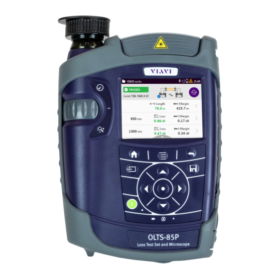
NTRODUCTION OLTS-85/OLTS-85P L OLTS-85/OLTS-85P Loss Test Set The SmartClass™ Fiber OLTS-85/OLTS-85P (optical loss test set) contents high-performance, easy-to-use instruments with a two or four wavelength light source and a power meter. They are universal instruments for Tier 1 certification of single-mode and multi-mode fibers, installation, maintenance, and troubleshooting. -
Page 9: Olts-85/Olts-85P Light Sources
NTRODUCTION OLTS-85/OLTS-85P L IGHT OURCES OLTS-85/OLTS-85P Light Sources The SmartClass™ Fiber OLTS-85/OLTS-85P light sources are professional, versatile, compact handheld instruments designed for qualification and certification of fiber optic networks. Carefully chosen combinations of available wavelengths make SmartClass™ Fiber OLTS-85/OLTS-85P light sources the optimum choice for link loss testing and characterization of long-haul, metro, and access telecommunication networks, as well as for data center and local area network testing. -
Page 10: Operating Manual Update
If the operating instructions about features supported by your instrument are missing, please visit the Viavi web site to check if additional information is available. To download the latest user manual: Visit the Viavi web site at http://updatemyunit.net. -
Page 11: Symbols Used In This Operating Manual
NTRODUCTION YMBOLS USED IN THIS OPERATING MANUAL Symbols used in this operating manual Various elements are used in this operating manual to draw attention to special meanings or important points in the text. Symbols and terms used in warnings The following warnings, symbols, and terms are used in this document in compliance with the American National Standard ANSI Z535.6-2011: NOTICE... - Page 12 NTRODUCTION YMBOLS USED IN THIS OPERATING MANUAL Warning format All warnings have the following format: WARNING Type and source of danger Consequences of ignoring the warning. Action needed to avoid danger. The following elements are used in this operating manual: Requirement This requirement must be met first;...
-
Page 13: Safety Information
AFETY NFORMATION ARNING SYMBOLS ON THE UNIT AFETY NFORMATION Warning symbols on the unit Warning symbols indicating a potential hazard In all cases where the unit is labeled with a warning symbol, the operating manual must be consulted to learn more about the nature of the potential hazard and any action that must be taken. -
Page 14: Laser Safety
AFETY NFORMATION ASER SAFETY Laser safety WARNING Dangerous laser radiation Laser radiation can cause irreparable damage to eyes and skin. This device is a Class 1 laser product according to DIN EN 60825-1:2007. The maximum permitted power for the OLTS-85/OLTS-85P means that the optical input signals can reach hazard level. -
Page 15: Ventilation
AFETY NFORMATION ENTILATION Ventilation NOTICE Insufficient ventilation Insufficient ventilation can damage the instrument or adversely affect its function and safety. Ensure adequate ventilation when operating the instrument. PS4 Universal AC/DC Power Supply Safety class The PS4 Universal AC/DC Power Supply unit has a protective isolation that conforms with IEC 60950. - Page 16 AFETY NFORMATION PS4 U AC/DC P NIVERSAL OWER UPPLY NOTICE Condensation Operation in the presence of condensation can damage the PS4 Universal AC/DC Power Supply or adversely affect its function and safety. Do not operate the PS4 Universal AC/DC Power Supply if condensation has formed.
-
Page 17: Getting Started
This is particularly likely if the packaging is visibly damaged. If there is damage, do not attempt to operate the instrument. Doing so can cause further damage. In case of damage, please contact your local Viavi sales company. Addresses can be found at www.viavisolutions.com. Recovery following storage/shipping Condensation can occur if an instrument that is stored or shipped at a low temperature is brought into a warm room. - Page 18 ETTING TARTED NPACKING THE INSTRUMENT Instrument overview Fig. 1 Front view OLTS-85/OLTS-85PP (left) and OLTS-85/OLTS-85P Patch cord microscope (PCM) with FMAE adapter PCM controls: focus control, automated Pass/Fail analysis, magnification control Connector interface Test head cover (green for APC- and gray for PC connectors) 3.5 inch touchscreen Key pad (operator control panel) Battery compartment and stand (on rear of instrument)
- Page 19 ETTING TARTED NPACKING THE INSTRUMENT Connector panel Fig. 2 Connector panel Optical connector 1, single-mode Optical connector 2, multi-mode Input port for broadband measurement Fig. 3 External power supply connector and communication inter- faces Ethernet port (RJ-45) External power supply connector USB 2.0 host port (Type A) USB 2.0 device port (Type Micro-B) OLTS-85/OLTS-85P...
- Page 20 ETTING TARTED NPACKING THE INSTRUMENT Power supply The following power sources can be used to operate the OLTS-85: • Eight 1.5 V dry batteries (Mignon AA size, alkaline type recommended) • Eight 1.2 V NiMH rechargeable batteries (Mignon AA size, no internal charge) •...
- Page 21 ETTING TARTED NPACKING THE INSTRUMENT Replacing batteries Fig. 4 Replacing the batteries RBP2 Li-Ion Battery Pack Latch lock AA battery tray The battery compartment is on the back of the instrument. Press down the latch to release and to open the lid of the battery compartment.
- Page 22 ETTING TARTED NPACKING THE INSTRUMENT NOTE: Rechargeable AA batteries will not be recharged in the instrument. For AA-type rechargeable batteries please use an external charger. It is not possible to charge the rechargeable AA batteries or the RBP2 Li-Ion Battery Pack via the USB interface. If the PS4 Universal AC/DC Power Supply and the USB interface are both connected, the instrument is powered by the PS4 Universal AC/DC Power Supply.
- Page 23 You will often be able to return used batteries to the place where you purchase new ones. Any dry or rechargeable batteries that you purchased from Viavi can be returned to one of our Service Centers for disposal. OLTS-85/OLTS-85P...
- Page 24 ETTING TARTED NPACKING THE INSTRUMENT Operation with AC power NOTE: Only the PS4 Universal AC/DC Power Supply may be used to operate the OLTS-85/OLTS-85P with AC power. To fit the AC line plug adapter: Select the appropriate AC line plug adapter. Slide the AC line plug adapter into the slot.
-
Page 25: Connecting Optical Cables
The OLTS-85/OLTS-85P cannot be powered via the USB interface. Connecting optical cables Mounting test adapters Viavi provides a number of test adapters for connecting the OLTS-85/OLTS-85P to the interface to be tested. You can connect all standard optical connector types to the instrument using these adapters. - Page 26 ETTING TARTED ONNECTING OPTICAL CABLES To mount the SENKO test adapter: The optical connectors are properly cleaned (see “Cleaning the test port” on page 115). Open the head cover and remove the protective cap (if still mounted). Unscrew the SENKO test adapter and pull it off vertically. Place the SENKO test adapter vertically on the optical connector.
-
Page 27: Basic Operation
ASIC PERATION WITCHING THE INSTRUMENT ON ASIC PERATION Switching the instrument on/off To switch the instrument on: Press the key to switch on the instrument. To switch the instrument off: Press the key to shift the instrument into hibernate mode. –... -
Page 28: Menus And Display Elements
ASIC PERATION ENUS AND DISPLAY ELEMENTS Menus and display elements Home screen The available menus and functions depend on the selected project type: Test-Tool project (TTP) or Workflow project (WP). Fig. 8 Home screens: Test-Tool Mode (screen shows PCM version) (1), Workflow Mode (2), Management (3), Settings (4) OLTS-85/OLTS-85P... - Page 29 ASIC PERATION ENUS AND DISPLAY ELEMENTS Menu See page Dashboard in Test-Tool Mode In this menu you can open test applications. Dashboard in Workflow Mode In this menu you can activate a label list and start a test. Management In this menu you can: •...
- Page 30 ASIC PERATION ENUS AND DISPLAY ELEMENTS Test-Tool Mode The Test-Tool Mode is enabled when a Test-Tool project is activated (for further information see “Managing projects” on page 42). Fig. 9 Dashboard in Test-Tool Mode Application See page Loss / Length To determine the total amount of loss or attenuation of a fiber link, the fiber length, and polarity.
- Page 31 ENUS AND DISPLAY ELEMENTS Workflow Mode NOTE: A workflow project can be generated and downloaded to the device only with Viavi's Cloud-based Enterprise Workflow Management Tool CERTiFi. For more information please refer to www.viavisolutions.com Fig. 10 Dashboard in Workflow Mode Active project The name of the active project is displayed.
- Page 32 ASIC PERATION ENUS AND DISPLAY ELEMENTS Status icons The status of the complete project, a certain label list, or a single label is shown by icons: Test not yet started. Test in progress. All completed tests have passed. The filled segment of the circle does not represent the actual progress.
- Page 33 ASIC PERATION ENUS AND DISPLAY ELEMENTS Elements in the top bar Project title Indicates the title of the active project WIFI Indicates that Wifi is installed. It does not indicate an active Wifi connection. Bluetooth Indicates that Bluetooth is installed. It does not indicate an active bluetooth connection.
-
Page 34: Navigating In The Menus
ASIC PERATION AVIGATING IN THE MENUS Navigating in the menus Press the key to open the home screen. Depending on the active project type the Projects tab shows the available test applications or the active Workflow project. Press the key to open the context-sensitive menu. Depending on which application is selected, a different menu opens. -
Page 35: Changing System Settings
ASIC PERATION HANGING YSTEM ETTINGS Changing System Settings In the Settings menu you can change instrument settings, get information and help about the instrument, or update the firmware. To open the Settings menu: The home screen is displayed. Select the tab. - Page 36 ASIC PERATION HANGING YSTEM ETTINGS Icon Function See page WiFi To configure the wireless local area networks. The last selected item is displayed in magenta. Bluetooth To configure the Bluetooth interface. Brightness To adjust the display brightness. Help To show device information SW Options To check and install software options.
- Page 37 ASIC PERATION HANGING YSTEM ETTINGS Setting the [Screen-Off] interval When [Screen-Off] is set, the display will switch off after the selected interval without any user action. NOTE: [Screen-Off] is only active when no external power supply is connected. In the menu tap the [More] button,...
- Page 38 ASIC PERATION HANGING YSTEM ETTINGS To set 24-hour or 12-hour time: Tap [Time Format]. Select the desired time format. Setting the Ethernet protocol In the menu tap the [More] button, then tap [Ethernet]. To select the IP mode: Tap the [IP Mode] button.
-
Page 39: Wifi Menu (Optional)
ASIC PERATION I MENU OPTIONAL In the menu tap the [More] button, then tap [Set to default]. [Yes] to proceed. – or – [No] to cancel. WiFi menu (optional) In the menu tap the [WiFi] button. Editable settings are displayed –... -
Page 40: Updating The Firmware
The latest version of the firmware can be downloaded from the Internet. To find the latest firmware version: Visit the Viavi web site at http://updatemyunit.net. Select your model from the product line. Open the download area and download the latest firmware. - Page 41 ASIC PERATION REATING SCREENSHOTS Set the Add Auto-Increment Number function ON or OFF. If the setting is ON, a number is added to the proposed name, ascending each time that a new screenshot is taken. Edit the Auto-Increment Number field by tapping the pencil button if you want to change the current number.
-
Page 42: Managing Projects
NOTE: Test-Tool projects can be created and edited on the device. Workflow projects can be created only in Viavi's Cloud-based Enterprise Workflow Management Tool CERTiFi. It needs to be downloaded to the device from a Mobile App. (see “Workflow mode”... - Page 43 ANAGING PROJECTS OOL MODE Selecting a Test-Tool project The home screen is displayed. Select the tab, then tab the [Projects] button. The projects available on the instrument are displayed. Select a project, press the key and tap [Set Active]. Press the key to open the dash board menu.
- Page 44 ANAGING PROJECTS OOL MODE Adding a new project: Press the key. The edit menu opens. Tap [Add]. The title edit menu opens. Type in the project title and tap The project is created and displayed in the list. Copying an existing project: Select the project you wish to copy.
-
Page 45: Workflow Mode
ANAGING PROJECTS ORKFLOW MODE The changes are immediately effective. Press the button to close the edit menu. Deleting a Test-Tool project Select the project you wish to delete. Press the key and tap [Remove]. [Yes] to permanently delete the project. The project is deleted and removed from the list. - Page 46 ANAGING PROJECTS ORKFLOW MODE Select a project, press the key and tap [Set Active] If a Workflow project is already active you also can select a project from the Workflow dashboard (see next section). Selecting a project from the Workflow dashboard If a Workflow project is already active you can select another project directly from the Workflow dashboard instead of opening the Job Management menu.
- Page 47 ANAGING PROJECTS ORKFLOW MODE NOTE: Savings of measurement results are assigned to the selected project. Selecting a label list Select the menu. The active project and the active label list are displayed. Tap the displayed label list. The available label lists are displayed. Tap a label list to activate it.
-
Page 48: Loss /Length Test Operation
ENGTH PERATION ENERAL INFORMATION ENGTH PERATION General information Loss/Length mode is used to measure loss, length, and polarity of a fiber. Depending on your specific needs a great variety of test types and settings are available: • Loopback test with one OLTS-85/OLTS-85P instrument •... -
Page 49: Adjusting General Test Settings
ENGTH PERATION DJUSTING GENERAL TEST SETTINGS How to perform a Loss/Length test A Loss/Length test consists of several steps to achieve reliable results. These steps are: Step Action See page “Adjusting general test settings” E.g. select the instrument or cable type. “Defining a test configuration”... - Page 50 ENGTH PERATION DJUSTING GENERAL TEST SETTINGS Fig. 13 Remote/Local adhesive labels To change the instrument type: The instrument is in Loss/Length mode. Press the key. Tap the [Device Type] button and choose Local or Remote. NOTE: In the measurement display Local and Remote are represented by the icons .
- Page 51 ENGTH PERATION DJUSTING GENERAL TEST SETTINGS Tap the desired manufacturer and cable name. – or – To add further cable types, change, or delete existing ones, press the key and tap the desired button. To change the length unit: The instrument is in Loss/Length mode. Press the key.
-
Page 52: Defining A Test Configuration
ENGTH PERATION EFINING A TEST CONFIGURATION Defining a test configuration In Loss/Length mode a test configuration allows you to define various settings like the test reference method or the cable and connector settings. When performing a test a predefined test configuration can be recalled and set to active to assign it. - Page 53 ENGTH PERATION EFINING A TEST CONFIGURATION The edit menu opens: Tap [Add]. The title edit menu opens. Type in the title and tap The test configuration is created and displayed in the list. To copy an existing test configuration: Select the test configuration you wish to copy. Press the key and tap [Copy].
- Page 54 ENGTH PERATION EFINING A TEST CONFIGURATION Editing a test configuration NOTE: You can not change the name of an existing test configuration. To change the name copy the configuration, type in the new name and delete the configuration you wished to change. The instrument is in Loss/Length mode and configured as Local.
-
Page 55: Referencing
ENGTH PERATION EFERENCING Description Description of the test configuration The description will be shown in the test configuration list below the title Test Type The test type can be set to Loopback or Remote. Depending on your instrument hardware configuration the device can be configured for Single-Mode or Multi-Mode measurements. - Page 56 ENGTH PERATION EFERENCING – remote or loopback – 1, 2, or 3 jumper cable The icons in the top bar show the status of the connection. Remote, no connection Remote, connection Loopback, no connection Loopback, connection L and R show local and remote instrument. When cabling is accepted the referencing start button is displayed.
- Page 57 ENGTH PERATION EFERENCING The display shows that referencing is in progress. After a successful referencing the start window and the Auto Test] button are displayed. NOTE: For more information about referencing see “Appendix - Referencing Methods” on page 116. OLTS-85/OLTS-85P...
-
Page 58: Running And Viewing A Loss/Length Test
ENGTH PERATION Loss/Length UNNING AND VIEWING A TEST Example loss limit calculation Number of connectors: 2 Number of splices: 1 Fig. 16 Performing the single-mode or multi-mode measurement Settings • 2 connectors • One jumper cable reference • 1 splice •... - Page 59 ENGTH PERATION Loss/Length UNNING AND VIEWING A TEST If bidirectional test is set, change the cords and tap button. – or – Press and tab [Auto Test]. While running, is displayed followed by briefly showing when test has passed or failed. Then the test result overview is displayed.
- Page 60 ENGTH PERATION Loss/Length UNNING AND VIEWING A TEST Test configuration, in this case remote test, local side Auto test start button Measured length and margin. In this case margin shows the maximum length defined by the selected test limit. Measured loss and margin of wavelength 1 / 2 When measured bidirectionally the larger loss of both measurement is displayed.
- Page 61 ENGTH PERATION Loss/Length UNNING AND VIEWING A TEST Selected tab: Loss for 1310 nm in this example Maximum loss as defined by selected test limit Loss of fiber 1 / fiber 2 Due to bidirectional measurement both values for Local to Remote and Remote to Local are displayed.
-
Page 62: Saving Loss/Length Test Results
ENGTH PERATION AVING ENGTH TEST RESULTS Saving Loss/Length test results Before starting a measurement a project must be selected and set to active. Thus, all results are assigned to that project when saved. If no project was defined by the user, the instrument will use the Test-Tool project “default”, which is always present (see “Managing projects”... - Page 63 ENGTH PERATION AVING ENGTH TEST RESULTS Tap the pen in the [Label] field to type a new label. A number will be appended automatically, if not already provided by the user. Tap the [Increment or the [Decrement button to adjust the label number, if needed.
-
Page 64: Loss Test Operation
PERATION ENERAL INFORMATION PERATION General information The Loss test operation is used to measure loss of a fiber loop or any optical component connected to the loop. When running a loss test, the internal laser source and powermeter are locked. Compared to the Loss/Length test operation the Loss mode allows real time measurement (values and changes are displayed while measuring) and can be run easily by setting up just a view... -
Page 65: Selecting A Port And Wavelength
PERATION ELECTING A PORT AND WAVELENGTH Fig. 17 Measurement display Loss Test Fig. 18 Edit menu Loss Test Selecting a port and wavelength Tap the desired wavelength(s) in the measurement display (only single-mode or multi-mode can be selected). – or – Press the key, tap [Select ... -
Page 66: Referencing
PERATION EFERENCING To switch between dB and Pass/Fail: From the measurement display press the key and tap [dB] or [Pass/Fail]. Referencing The actual measured power level relative to a reference value is displayed in relative power display mode. The reference value can be set by defining the actual power level as the reference value or can be edited manually. - Page 67 PERATION EFERENCING Editing reference and limit values manually Fig. 19 Editing Reference and Limit Editing a reference value The reference values can be set for each wavelength manually. The instrument is in Loss Test mode. Press the key, tap [More] and tap [Edit Ref.
-
Page 68: Pass/Fail Indication
PERATION AIL INDICATION Pass/Fail indication Pass/Fail indication for losses is only available in Loss Test mode. When performing fiber certification, the loss of the fiber system under test must be measured and compared to a loss limit to provide a loss margin. The loss limit is the maximum allowable loss of the overall system and is based on the following factors: •... -
Page 69: Performing The Measurement
PERATION ERFORMING THE MEASUREMENT Performing the measurement Laser is switched on. Connect your fiber system under test as shown below. Fig. 20 Performing the measurement Laser source output (Transmitter) Powermeter input (Receiver) Fiber system under test Viewing test results The measured loss is displayed in real time. Fig. -
Page 70: Saving Loss Test Results
PERATION AVING OSS TEST RESULTS Saving Loss test results Before starting a measurement a project must be selected and set to active. Thus, all results are assigned to that project when saved. If no project was defined by the user, the instrument will use the Test-Tool project “default”, which is always present (see “Managing projects”... - Page 71 PERATION AVING OSS TEST RESULTS Press the key again or tap the [Save] button. The measurement is stored in the current active project. NOTE: When measuring two wavelengths at a time both wavelengths are stored separately. Thus, the ID is incremented by 2. NOTE: If the label/fiber ID is not changed, the data set will be saved under the same title.
-
Page 72: Powermeter Operation
OWERMETER PERATION ENERAL INFORMATION OWERMETER PERATION General information This chapter describes how to use the OLTS-85/OLTS-85P as a power meter. In Powermeter mode up to two wavelengths can measured simultaneously. Results can be displayed as absolute level in dBm/Watt, relatively to a reference value in dB or as Pass/ Fail indication based on predefined limits. - Page 73 OWERMETER PERATION ETTING AND SELECTING WAVELENGTHS Fig. 23 Measurement display (screen shows the settings menu) Creating and editing wavelengths in the table In the [Edit menu wavelengths can be added and Table] deleted. Furthermore for each wavelength the reference value and the limit can be defined.
- Page 74 OWERMETER PERATION ETTING AND SELECTING WAVELENGTHS Select the desired wavelength. Press the key and tap the [Delete button. To edit the reference value: The Edit Table menu in Powermeter mode is displayed. Select the desired wavelength. Press the key and tap the [Edit Reference] button.
-
Page 75: Enabling Auto- Mode
NABLING L MODE Enabling Auto- mode Auto is a special feature developed by Viavi that allows you to identify wavelengths automatically (from OLS-XX, MTS-2k/4k/6k OTDR CW-source). To do this, the signal is modulated at a certain frequency (by a light source equipped with Auto ), which can be detected by a Viavi OLTS-85/OLTS-85P. -
Page 76: Selecting And Changing The Power Display Mode
OWERMETER PERATION ELECTING AND CHANGING THE POWER DISPLAY MODE Selecting and changing the power display mode The OLTS-85/OLTS-85P provides following display modes: • absolute power level in dBm or Watt • power level in dB relatively to a reference value •... -
Page 77: Saving Powermeter Test Results
OWERMETER PERATION AVING OWERMETER TEST RESULTS The actual power level is set as the new reference level. The reference level is displayed underneath the wavelength. Reference power level display mode is activated. NOTE: The reference level is stored for each wavelength and is saved even when the power is off. - Page 78 OWERMETER PERATION AVING OWERMETER TEST RESULTS Defined label name. Tap field to edit label name. • Probe: Number of already saved probe results. • Powermeter: Number of already saved powermeter results. • PCM: Number of already saved PCM results. • Loss/Length: Number of already saved loss/length results. •...
-
Page 79: Source Operation
The output signals of the light sources may be either continuous wave (CW) or modulated at certain frequencies, i.e. 270 Hz, 1 kHz, or 2 kHz. Viavi power meters (e.g. OLP-3x, OLP-8x, MTS- 2k/4k/6k) are capable of detecting these modulation frequencies. - Page 80 OURCE PERATION ENERAL INFORMATION Display elements Fig. 24 Source operation display, laser off (left) and on. Output port buttons Port not selected / port selected / port selected and laser on Tap to select/deselect. Mode button (modulation) Constant wave > 270 Hz > 1 kHz > 2 kHz > ... Tab button to skip through options.
-
Page 81: Selecting An Output Port And Wavelength
The OLTS-85/OLTS-85P provides two Auto- modes: • Multi-: Multi- is a proprietary Viavi solution that reduces testing time to a minimum by simultaneously testing at both wavelengths. When activated both wavelength are measured and displayed simultaneously. -
Page 82: Selecting A Modulation Or Auto- Mode
• The wavelength encoding cannot be detected due to interference. • You are measuring the absolute level of a system that does not have wavelength encoding matching Viavi power sources. Selecting a modulation or Auto- mode Modulation or Auto- mode can be selected by the mode button or via the menu. -
Page 83: Setting The Power Level
OURCE PERATION ETTING THE POWER LEVEL Enabling Multi- or Serial- (two wavelengths) NOTE: Multi- and Serial- can only be enabled when two wavelengths are selected. Using the [Mode selection] button: Tap the [Mode selection] button until Auto- is displayed. Activate more than one wavelength by tapping. Tap the [Mode selection] button to select Multi-... -
Page 84: Switching On/Off The Laser
OURCE PERATION WITCHING ON OFF THE LASER Switching on/off the laser To switch on the laser, tap the [Laser on/off] button. – or – Press the center key within the arrow keys. – or – Press the key and tap the [Output button. -
Page 85: Measuring Loss With
10 M EASURING OSS WITH OURCE OWERMETER ENERAL INFORMATION EASURING OSS WITH OURCE OWERMETER General information The OLTS-85 offers three different measurement modes. • Source Mode: The instrument works as a laser source. • Powermeter Mode: The instrument works as an optical power meter. -
Page 86: Viewing Test Results
10 M EASURING OSS WITH OURCE OWERMETER IEWING TEST RESULTS Fig. 25 Performing the measurement (for both directions by switching source and powermeter mode) Connection Source device Powermeter device Fiber system under test Viewing test results The measured loss is displayed in real time. Fig. -
Page 87: Saving Loss Test Results
10 M EASURING OSS WITH OURCE OWERMETER AVING OSS TEST RESULTS Fig. 27 Result overview over two wavelengths Saving Loss test results Before starting a measurement a project must be selected and set to active. Thus, all results are assigned to that project when saved. - Page 88 10 M EASURING OSS WITH OURCE OWERMETER AVING OSS TEST RESULTS Defined label name. Tap field to edit label name. • Probe: Number of already saved probe results. • Powermeter: Number of already saved powermeter results. • PCM: Number of already saved PCM results. •...
-
Page 89: Probe /Pcm Operation
11 P /PCM O ROBE PERATION ENERAL INFORMATION /PCM O ROBE PERATION General information Dirty and/or damaged connectors are often the root cause of optical network problems. The Probe and PCM applications enable industry standard inspection and automated Pass/Fail testing with report generation of optical connectors/adapters in order to ensure industry standard fiber endface quality and cleanliness. -
Page 90: The External P5000I Digital Probe
11 P /PCM O ROBE PERATION P5000 HE EXTERNAL IGITAL ROBE Fig. 28 Patch cord microscope components FMAE adapter QuickCapture™ key Focus Control Magnification Control key FMAE series adapters for the PCM SmartClass™ Fiber devices with the PCM use FMAE series adapters to ensure consistent and accurate inspection for a wide variety of connectors and applications. - Page 91 11 P /PCM O ROBE PERATION P5000 HE EXTERNAL IGITAL ROBE levels: low magnification (around 23000 dpi) for overview inspection of the fiber endface, and high magnification (around 46000 dpi) for detailed inspection of the fiber endface. The P5000i Digital Probe kit sold with the OLTS-85/OLTS-85P contains the standard barrel assembly (FBPP-BAP1), standard patch cord tips, and standard bulkhead tips.
-
Page 92: Basic Settings
11 P /PCM O ROBE PERATION ASIC SETTINGS Fig. 30 FBPT series tips for the P5000i Inspection tip Barrel assembly P5000i connection The Probe application requires a P5000i Digital Probe in order to be fully functional (see the list of all accessories in “Accessories”... - Page 93 11 P /PCM O ROBE PERATION ASIC SETTINGS To switch on/off auto center: Press the key. Tap the [More] button. Tap [PCM Settings] or [Probe Settings]. Tap [Auto Center] to toggle on/off. QuickCapture™ key In order to support different workflows, the functionality of the QuickCapture™...
-
Page 94: Selecting A Profile And Adapter/Tip
11 P /PCM O ROBE PERATION ELECTING A PROFILE AND ADAPTER Selecting a profile and adapter/tip About profiles Profiles contain the analysis parameters from which pass/fail criteria are determined. A number of profiles are supplied with the instrument. Profiles cannot be created in the instrument but with the FiberChekPRO™... -
Page 95: Operation
11 P /PCM O ROBE PERATION PERATION To select an adapter/tip: Press the key. Tap the [Tip]/[Adapter] button. Select the suitable adapter/tip. Operation Adjusting the focus Use the focus control to adjust the sharpness. NOTE: The focus quality bar helps you to find the best setting (see “Focus quality bar”... - Page 96 11 P /PCM O ROBE PERATION PERATION Zone Represents the core zone. It is the area surrounding the core. Represents the cladding zone. It surrounds the majority of the fiber cladding. Represents the epoxy ring. Represents the ferrule zone. It identifies a portion of the ferrule near and around the fiber.
-
Page 97: Saving Probe/Pcm Results
11 P /PCM O ROBE PERATION /PCM AVING ROBE RESULTS To return to the live image: Press the QuickCapture™ key. – or – Press the key and tap the [Live] button. Saving Probe/PCM results Images can easily be saved by pressing the key. - Page 98 11 P /PCM O ROBE PERATION /PCM AVING ROBE RESULTS As file name the label prefix defined in the project settings is showed on top of the display. To edit the file name, tap the name, edit it and tap [OK]. To change the ID, tap [Decrement or [Increment ID].
-
Page 99: Workflow Mode
Test-Tool mode and described in the corresponding chapters. NOTE: The workflow mode can be enabled only through Viavi's Cloud- based Enterprise Workflow Management Tool CERTiFi. For more information please refer to www.viavisolutions.com Performing a measurement in Workflow... - Page 100 12 W ORKFLOW MODE ERFORMING A MEASUREMENT IN ORKFLOW MODE Loading a project from the Mobile Application Workflow projects can simply transferred via the Mobile App to the instrument. NOTE: For further information about the Mobile Application please refer to the help provided with the application. Selecting a project on the instrument For further information about selecting a workflow project and label list on the instrument see...
- Page 101 12 W ORKFLOW MODE ERFORMING A MEASUREMENT IN ORKFLOW MODE Display shows that referencing is in progress. Running a test In the menu tap the [START TEST] button. The labels of the active label list are displayed. Tap the label to be tested. The defined tests are displayed.
- Page 102 12 W ORKFLOW MODE ERFORMING A MEASUREMENT IN ORKFLOW MODE Tab the test to be performed (. The test is started. Buttons are showing the status: (see “Viewing the test progress” on page 103) After completion of the measurement the results are displayed in the results overview window (e.g.
-
Page 103: If A Test Has Failed / Repeating A Test
12 W ORKFLOW MODE F A TEST HAS FAILED REPEATING A TEST NOTE: A test can be run several times and saved again. If already reported the new results will substitute the previous results in the mobile and cloud app, but not be deleted in the instrument data storage. -
Page 104: Managing Workflow Projects
12 W ORKFLOW MODE ANAGING ORKFLOW PROJECTS Managing Workflow projects Workflow projects only can be created and managed from the web based Project Management Application. The OLTS-85/ OLTS-85P does not allow to create or edit Workflow projects. OLTS-85/OLTS-85P... -
Page 105: Data Management
13 D ANAGEMENT AVING RESULTS ANAGEMENT NOTE: Results are always stored under the currently selected (active) project. Thus, to display stored results the desired project must be set to active first (see “Managing projects” on page 42). To select a project see “Selecting a Test-Tool project”... - Page 106 13 D ANAGEMENT ATA MANAGEMENT OF ENGTH TESTS The list of stored test results is displayed. NOTE: When measuring two wavelengths at a time, both wavelengths are stored separately together with the length results. Thus, two entries can be found in the list for this test. See example above: Pre7 [1] and Pre7 [2] show the same timestamp.
-
Page 107: Data Management Of Loss And Powermeter Tests
13 D ANAGEMENT ATA MANAGEMENT OF OSS AND OWERMETER TESTS Select the length or wavelength tab to show the test results for length and loss measurement in detail. For more information about the test result details see “Viewing test results” on page Press the right/left arrow keys to show the next/previous test results, e.g. - Page 108 13 D ANAGEMENT ATA MANAGEMENT OF OSS AND OWERMETER TESTS Fig. 32 Measurement data overview: Loss Test (left), Powermeter Test (right) To show all columns of the overview: Press the right/left arrow keys to show additional information. The displayed information depends on the selected application.
- Page 109 13 D ANAGEMENT ATA MANAGEMENT OF OSS AND OWERMETER TESTS Measurement Data of Powermeter Test mode Auto optional Auto Tone Tone value Timestamp Time and date of the test Managing test results To select/deselect a test result: There are several ways to select and deselect test results: Tap an entry once to highlight it, tap it again to select it.
-
Page 110: Data Management Of Probe And Pcm Tests
13 D ANAGEMENT Probe ATA MANAGEMENT OF TESTS To sort the test results: The measurement data overview is displayed. Press the key. Tap the [More] button, then tap the [Sort Order] button. Select the desired sorting order. To show or hide the overview columns: The measurement data overview is displayed. - Page 111 13 D ANAGEMENT Probe ATA MANAGEMENT OF TESTS To show all columns of the overview: Press the right/left arrow keys to show additional information. The displayed information depends on the selected application. Fiber ID Test label name Pass/Fail Passed/failed label Profile Profile label Adapter...
- Page 112 13 D ANAGEMENT Probe ATA MANAGEMENT OF TESTS To select multiple tests: Repeat step 1 to select multiple entries. To select all tests: Press the key and tap [Select All]. To deselect all tests: Press the key and tap [Deselect All]. Displaying test results NOTE: When selecting multiple tests, all selected tests can be viewed...
-
Page 113: Exporting Results To Usb
13 D ANAGEMENT XPORTING RESULTS TO Deleting stored results from a project The measurement data overview is displayed. Select one, multiple or all tests. Press the key. Tap the [Delete Selected] button. The selected test results are deleted. Actions when viewing images To toggle the image magnification low/high Press the key, then tap the... -
Page 114: Importing Test Results From Another Unit
Remote to Local. Making a report In order to make a report, please download the FiberChekPRO™ or SmartReporter software from the Viavi web site http://updatemyunit.net. Connect your instrument to your PC via the USB port and follow the instructions on the screen. -
Page 115: Maintenance
14 M AINTENANCE LEANING THE TEST PORT AINTENANCE WARNING Dangerous voltage and invisible laser radiation Maintenance or cleaning of the instrument while it is con- nected or operating may damage the instrument or injure you. Make sure that the instrument is switched off and disconnected from all power sources and optical radiation sources before maintenance or cleaning. -
Page 116: Appendix - Referencing Methods
15 A PPENDIX EFERENCING ETHODS OOPBACK AND EMOTE EFERENCING PPENDIX EFERENCING ETHODS For a fiber loss measurement per length, connection, and splice, the technician must indicate the fiber length, the number of connections, and how many splices are present in the fiber system under test. - Page 117 15 A PPENDIX EFERENCING ETHODS OOPBACK AND EMOTE EFERENCING Fig. 34 Loopback Referencing: 1-jumper cable (1), 2-jumper cable (2), 3-jumper cable (3) Laser source output (Transmitter) Powermeter input (Receiver) Remote Referencing One jumper cable reference This reference removes the losses at Connection 1 and Connection 4 from the measurement.
- Page 118 15 A PPENDIX EFERENCING ETHODS OOPBACK AND EMOTE EFERENCING Fig. 36 One jumper reference - bidirectional (switching source and powermeter mode) Connection 1 Connection 4 Laser source output (Transmitter) Powermeter input (Receiver) Source device Powermeter device Measured loss = Δ + Δ...
- Page 119 15 A PPENDIX EFERENCING ETHODS OOPBACK AND EMOTE EFERENCING Limit Length of fiber conn2 conn3 conn4 splice5 conn6 x Loss/km 14763-3 Length of fiber (0.5dB) 0.75 dB 0.75 dB 0.3 dB (0.5dB) x Loss/km TIA/11801 Length of fiber (0.75 dB) 0.75 dB 0.75 dB 0.3 dB...
- Page 120 15 A PPENDIX EFERENCING ETHODS OOPBACK AND EMOTE EFERENCING Laser source output (Transmitter) Powermeter input (Receiver) Source device Powermeter device The losses (Δ) at Δ , Δ and Δ are referenced out, Conn. 1 Conn. 2 Conn. 4 so the loss measurement is as follows: Measured loss = Δ...
- Page 121 15 A PPENDIX EFERENCING ETHODS OOPBACK AND EMOTE EFERENCING Fig. 39 Three jumper reference - unidirectional Fig. 40 Three jumper reference - bidirectional (switching source and powermeter mode) Connection 1 Connection 4 Connection 2 Connection 3 Laser source output (Transmitter) Powermeter input (Receiver) Source device Powermeter device...
- Page 122 15 A PPENDIX EFERENCING ETHODS OOPBACK AND EMOTE EFERENCING This reference removes any loss at all the connections. A third reference jumper is used. Just as with the other test jumpers, the loss of this short reference jumper will not affect the loss measurement.
-
Page 123: Remote Control
16 R EMOTE ONTROL OOPBACK AND EMOTE EFERENCING EMOTE ONTROL Remote Command Documentation Please visit the Viavi web site at http://updatemyunit.net the latest Remote Command Documentation “SCF RC Docs.exe“ (self extracting zip-file). OLTS-85/OLTS-85P... -
Page 124: Environmental Compliance
The authority to operate this equipment is conditioned by the requirements that no modifications be made to the equipment unless the changes or modifications are expressly approved by Viavi. NOTE: To comply with FCC RF exposure compliance requirements, a separation distance of at least 20 cm must be maintained between the antenna of this device and all persons. - Page 125 17 E NVIRONMENTAL COMPLIANCE OOPBACK AND EMOTE EFERENCING EU Radio Equipment Directive In accordance with Article 10.8 of the EU Radio Equipment Directive 2014/53/EU, the following table provides information on the frequency bands and the maximum RF transmit power of this product for sale in the EU: Frequency range Channels used...
-
Page 126: Specifications
18 S PECIFICATIONS ENERAL SPECIFICATIONS PECIFICATIONS General specifications Fiber inspection Via P5000i Digital Probe with auto Pass/Fail analysis Live image 320 x 240 pixels, 8 bit gray, 10 fps Display High contrast 3.5" TFT color touchscreen Display resolution 0.01 dB / 0.001 µW Measurement units dB, dBm, W Data memory... -
Page 127: Power Meter Specifications
1) Under reference conditions: -20 dBm (CW), at 1310 nm ± 1 nm, 23 °C ± 3K, 9 μm test fiber with SC/PC ceramic connector 2) With Viavi Optical Light Source 800 nm to 1650 nm: for levels > -50 dBm... -
Page 128: Tier 1 Specifications
18 S PECIFICATIONS SPECIFICATIONS Output power (typical) –25 to –22 dBm 0 to –3 dBm settable in 0.1 dB steps Stability 15 min ±0.02 dB ±0.02 dB Stability ±0.2 dB ±0.2 dB Source modes CW, Tone, Auto-λ, Multi-λ Tone generator 270 Hz, 1 kHz, 2 kHz Laser safety IEC 60825-1:2007... -
Page 129: Ordering Information
• USB cable • Quick Start Manual and Safety Instructions • The latest Operating Manual, and FiberChekPRO™ reporting software can be downloaded at the Viavi web site http://updatemyunit.net. Additional items in SM Kit • SM test reference cord SC-LC, and LC-LC Additional items in MM Kit •... -
Page 130: Accessories
19 O RDERING NFORMATION CCESSORIES Accessories P5000i Digital Probe Microscope with FiberChekPRO™ FBP-P5000I software Calibration report BN 2325/ 90.01 UC4 hands free carrier for SmartClass™ Fiber BN 2128/01 UC4P hands free carrier for SmartClass™ Fiber with PCM BN 2128/02 OLTS-85/OLTS-85P... - Page 131 NDEX NDEX Control panel 27 Creating AC line plug adapter 24 new project 43 Activating new test configuration 52 project 45 test configuration 53 Adapters PCM/Probe 94 Damage during shipping 17 Adjusting Date & time, setting 37 focus (PCM/Probe) 95 Defining a test configuration 52 magnification (PCM/Probe) 95 Deleting...
- Page 132 NDEX Focus quality bar (PCM/Probe) 93 Mobile Application 7, 100 Focus, adjusting (PCM/Probe) 95 Modulated signal, displaying 75 Freezing the image (PCM/Probe) 96 Modulation (Source) 82 Image, freezing (PCM/Probe) 96 Navigating in the menus 34 Negative loss warning, activate/ deactivate 51 Job management, selecting a project On/off, instrument 27 Operation...
- Page 133 NDEX Powermeter Setting Auto-Lambda mode 75 auto-off 36 display mode 76 date & time 37 lambda table 73 display-off 37 Probe P5000i 90 Ethernet protocol 38 Profiles (PCM/Probe) 94 Shipping damage 17 Project Showing device Information 36 activating 45 Source creating 43 Auto-Lambda 82 deleting 45...
- Page 134 NDEX Wavelength (Source) 81 Workflow dashboard, selecting a project Workflow mode performing a measurement 99 running a test 101 selecting label list 47 Working with projects 42 OLTS-85/OLTS-85P...
- Page 135 Hazardous materials Viavi avoids or uses with care any hazardous or dangerous material in the manufacturing process or the end product. If the use of a dangerous material cannot be avoided, it is identified in product documentation and clearly labeled on the product itself.
- Page 136 EU Waste Electrical and Electronic Equipment (WEEE) Directive, 2012/ 19/EU, and the EU Battery Directive, 2006/66/EC. Instructions for returning waste equipment and batteries to JDSU can be found in the WEEE section of Viavi's Standards and Policies web page (https://www.viavisolutions.com/en-us/ corporate/legal/policies-standards#sustain).
- Page 137 RODUCT EGULATORY OMPLIANCE OLTS-85/OLTS-85P...
- Page 138 RODUCT EGULATORY OMPLIANCE OLTS-85/OLTS-85P...
- Page 139 North America +1 844-468 4284 Viavi product specifications and descriptions in Latin America +1 954 688 5660 this document are subject to change without China +86 21 6859 5260 notice. Germany +49 7121 86 0 © 2019 Operating manual SmartClass™ Fiber Optical Loss Test Sets OLTS-85/OLTS-85P...
Need help?
Do you have a question about the SmartClass OLTS-85 and is the answer not in the manual?
Questions and answers