
Related Manuals for J&M NitroGro 5010


Summary of Contents for J&M NitroGro 5010
- Page 1 Manual MODEL O P E R A T O R ’ S M A N U A L J&M Manufacturing Co, Inc 284 Railroad Street - P.O. Box 547 | Fort Recovery, OH 45846 | Ph: (419) 375-2376 | Fax: (419) 375-2708 www.jm-inc.com...
-
Page 2: Table Of Contents
Table Of Contents To The Dealer ....................4 Serial Number . - Page 3 Table Of Contents GEP Coulter Mount ..................42 GEP Coulter Assembly .
-
Page 4: To The Dealer
To The Dealer TO THE DEALER Read manual instructions and safety rules. Make sure all items on the Dealer’s Pre-Delivery and Delivery Check Lists are completed before releasing equipment to the owner. The dealer must complete the Warranty Registration found on the Dealer Portal website located at dealer.jm-inc.com and return it to J&M Mfg. -
Page 5: Serial Number
Serial Number Serial Number Location Serial Number______________________ Model Number_____5010 or 5016_____ Standard practice when ordering parts or obtaining information from your dealer requires the serial number and model number. Have numbers available before making contact. General Information TO THE OWNER: The purpose of this manual is to assist you in operating and maintaining your seed tender in a safe manner. -
Page 6: Safety Rules
Safety Rules ATTENTION! BECOME ALERT! YOUR SAFETY IS INVOLVED! Safety is a primary concern in the design and manufacture of our products. Unfortunately, our efforts to provide safe equipment can be erased by an operator’s single careless act. In addition, hazard control and accident prevention are dependent upon the awareness, concern, judgment, and proper training of personnel involved in the operation, transport, maintenance and storage of equipment. -
Page 7: Bolt Torque Chart
Bolt Torque Chart Always tighten hardware to these values unless a different torque or tightening procedure is listed for specific application. Fasteners must always be replaced with the same grade as specified in the manual parts list. Always use the proper tool for tightening hardware. Make sure fastener threads are clean and you start thread engagement properly. -
Page 8: Specifications
Specifications SPECIFICATIONS 5000 Series Applicators Tank Size 1,000 Gallon 1,600 Gallon Base Width 30’-0” 40’-0” Ground Clearance 34” 34” Row Spacing* 20”, 30” 20”, 30” Number of Coulters 11, 13, 15, 17, 23, 25 11, 13, 15, 17, 23, 25 Coulter Style Grove Engineered Products (GEP) Grove Engineered Products (GEP) -
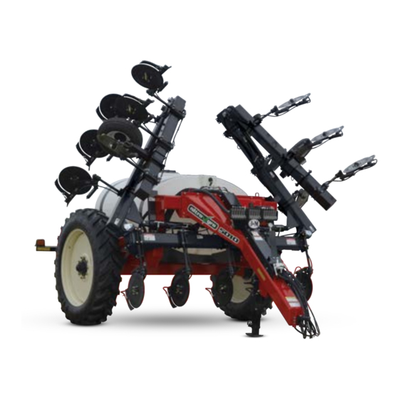
Page 9: Nitrogro Components
NitroGro Components Holding Tank Light Bar Flow Monitors (Optional) Hitch Toolbar Down Pressure Gauge Down Pressure Relief Valve Gauge Wheel Coulter 3-Section Boom Spike Shut Off Valve Agitation Valve Strainer Hydraulic Pump Rinse Tank Tank Fill Valve 2” or 3” Flow Monitors Flow monitors allow the operator to see the rate of flow to each coulter through a floating ball inside the transparent inspection tube. -
Page 10: Adjusting The Field Depth
Adjusting the Field Depth • Set the center section of coulters first. Spacers are included with the toolbar cylinders. Add or remove spacers until the center sec- tion is positioned at the appropriate depth. Lower the unit until the lift cylinders bottom out on the stroke control spacers. Add or remove stroke control spacers until the center toolbar section reaches desired application depth. -
Page 11: Coulter
Coulter The number of coulters is determined by the number of rows (usually one less or one more). So the number of rows will be even, and the number of coulters will be odd, since you are placing the nitrogen between the rows. Example, a 16 row unit will have either 15 or 17 coulters. -
Page 12: Strainer
Strainer The NitroGro applicator is equipped with a strainer designed to remove dirt and debris from the fertilizer to prevent downstream clogs. Shut-Off & Fill Valve The NitroGro applicator is standard equipped with a 2” shut-off and fill valve. There is an upgrade option for a 3”... -
Page 13: Pre-Operation Checklist
Pre-Operation Checklist IMPORTANT - Before putting the applicator into operation, check the machine for damaged or worn parts and replace as necessary. Wheel Nuts Tightened During initial operation, tighten standard 3/4” wheel studs and nuts to torque 400 ft-lbs. Re-check wheel nut torque settings during initial break in period (10, 20, 50 acres), then every 10 hours of use for the first 40 hours. -
Page 14: Hitching And Unhitching The Applicator
Hitching and Unhitching the Applicator Connect the applicator to the tow vehicle using a hitch pin and make sure a retaining pin is secured in the hitch pin. Always attach the safety chains to the applicator and the tow vehicle. WARNING –... -
Page 15: Transporting
Transporting • Comply with ALL state and local laws governing highway safety and regulations when moving machinery on public roads. • Be sure an SMV (Slow Moving Vehicle) emblem is in place and clearly visible on the rear of the applicator. Position the SMV emblem with one point of the triangle upward and as near to the rear and centered or as near to the left of center of the unit as practicable. -
Page 16: Wheel Spacing
Wheel Spacing • To set up the Applicator for 20” or 30” rows use the inside hole. This will set the wheel spacing at 120”. • To set up the Applicator for 22” rows use the outside hole. This will set the wheel spacing at 132”. -
Page 17: Operation
Operation Hook tractor to NitroGro and adjust hitch so that frame on applicator is level or tilting backward slightly. Connect hydraulic lines. See “Connecting the Hydraulic Hoses” on page 14. Unfold the unit. See “Folding & Unfolding” on page 14. Lower the unit until the lift cylinders bottom out on the stroke control spacers. -
Page 18: Troubleshooting
Troubleshooting WARNING - MAKE SURE THAT ALL POWER IS SHUT OFF BEFORE SERVICING THE APPLICATOR. MAINTENANCE AND REPAIR SERVICE WORK TO BE PERFORMED BY QUALIFIED SERVICEMEN ONLY. Trouble Possible Cause Possible Remedy Outside tool bar wing creeps Counterbalance valve is too loose Tighten counterbalance valve. -
Page 19: Flow Monitor Set Up
Flow Monitor Set Up The NitroGro applicator offers row spacing options of 20”, 22”, or 30”. The unit will be either be set up to or re-apply the outside row (“1 Up”), or skip a row (“1 Down”). Using your row spacing and whether your aplicator is “1 Up” or “1 Down”, refer to the chart below to determine the location and quantity of flow monitors for your applicator. -
Page 20: Injectors - 20" Row Spacing
Injectors - 20” Row Spacing 20 Gallons Per Acre 25 Gallons Per Acre Speed (MPH) #10 Injector (psi) #15 Injector (psi) #20 Injector (psi) #30 Injector (psi) #40 Injector (psi) GPM (per nozzle) 0.34 0.43 0.52 0.60 0.69 0.77 0.86 0.95 1.03 0.43 0.54 0.64 0.75 0.86 0.97 1.07 1.18 1.29 Flow Indicator 1/2"... - Page 21 Injectors - 20” Row Spacing 50 Gallons Per Acre 55 Gallons Per Acre Speed (MPH) #10 Injector (psi) 103 115 104 115 129 #15 Injector (psi) #20 Injector (psi) #30 Injector (psi) #40 Injector (psi) GPM (per nozzle) 0.86 1.07 1.29 1.50 1.72 1.93 2.15 2.36 2.58 0.95 1.18 1.42 1.66 1.89 2.13 2.36 2.60 2.84 Flow Indicator 1/2"...
-
Page 22: Injectors - 22" Row Spacing
Injectors - 22” Row Spacing 15 Gallons Per Acre Speed (MPH) #10 Injector (psi) #15 Injector (psi) #20 Injector (psi) #30 Injector (psi) #40 Injector (psi) GPM (per nozzle) 0.25 0.31 0.38 0.44 0.50 0.57 0.63 0.69 0.75 Flow Indicator Red Glass Level 1.1 1.7 Flow Indicator 1/2"... - Page 23 Injectors - 22” Row Spacing 40 Gallons Per Acre 45 Gallons Per Acre Speed (MPH) #10 Injector (psi) 102 114 #15 Injector (psi) #20 Injector (psi) #30 Injector (psi) #40 Injector (psi) GPM (per nozzle) 0.76 0.95 1.14 1.32 1.51 1.70 1.89 2.08 2.27 0.85 1.06 1.28 1.49 1.70 1.92 2.13 2.34 2.55 Flow Indicator 1/2"...
-
Page 24: Injectors - 30" Row Spacing
Injectors - 30” Row Spacing 15 Gallons Per Acre Speed (MPH) #10 Injector (psi) #15 Injector (psi) #20 Injector (psi) #30 Injector (psi) #40 Injector (psi) GPM (per nozzle) 0.34 0.43 0.51 0.60 0.68 0.77 0.86 0.94 1.03 Flow Indicator Red Glass Level Flow Indicator 1/2"... - Page 25 Injectors - 30” Row Spacing 40 Gallons Per Acre 45 Gallons Per Acre Speed (MPH) #10 Injector (psi) 115 128 143 113 132 146 163 #15 Injector (psi) #20 Injector (psi) #30 Injector (psi) #40 Injector (psi) GPM (per nozzle) 1.03 1.29 1.55 1.81 2.06 2.32 2.58 2.84 3.10 1.16 1.45 1.74 2.03 2.32 2.61 2.90 3.19 3.48 Flow Indicator 1/2"...
-
Page 26: Knife - 20" Row Spacing
Knife - 20” Row Spacing 10 Gallons Per Acre 15 Gallons Per Acre Speed (MPH) 0.075 Orifice Pressure (psi) 0.107 Orifice Pressure (psi) 0.132 Orifice Pressure (psi) 0.161 Orifice Pressure (psi) GPM (per nozzle) 0.15 0.19 0.23 0.27 0.30 0.34 0.38 0.42 0.46 0.23 0.29 0.34 0.40 0.46 0.51 0.57 0.63 0.68 Flow Indicator Red Glass Level 0.3 Flow Indicator 1/2"... - Page 27 Knife - 20” Row Spacing 40 Gallons Per Acre 45 Gallons Per Acre Speed (MPH) 0.075 Orifice Pressure (psi) 103 117 131 145 103 119 134 150 165 0.107 Orifice Pressure (psi) 0.132 Orifice Pressure (psi) 0.161 Orifice Pressure (psi) GPM (per nozzle) 0.61 0.76 0.91 1.07 1.22 1.37 1.52 1.67 1.83 0.68 0.86 1.03 1.20 1.37 1.54 1.71 1.88 2.05 Flow Indicator 1/2"...
-
Page 28: Knife - 22" Row Spacing
Knife - 22” Row Spacing 10 Gallons Per Acre 15 Gallons Per Acre Speed (MPH) 0.075 Orifice Pressure (psi) 0.107 Orifice Pressure (psi) 0.132 Orifice Pressure (psi) 0.161 Orifice Pressure (psi) GPM (per nozzle) 0.17 0.21 0.25 0.29 0.33 0.38 0.42 0.46 0.50 0.25 0.31 0.38 0.44 0.50 0.57 0.63 0.69 0.75 Flow Indicator Red Glass Level Flow Indicator 1/2"... - Page 29 Knife - 22” Row Spacing 40 Gallons Per Acre 45 Gallons Per Acre Speed (MPH) 0.075 Orifice Pressure (psi) 100 116 131 146 161 116 133 150 167 184 0.107 Orifice Pressure (psi) 0.132 Orifice Pressure (psi) 0.161 Orifice Pressure (psi) GPM (per nozzle) 0.67 0.84 1.00 1.17 1.34 1.51 1.67 1.84 2.01 0.75 0.94 1.13 1.32 1.51 1.70 1.88 2.07 2.26 Flow Indicator 1/2"...
-
Page 30: Knife - 30" Row Spacing
Knife - 30” Row Spacing 10 Gallons Per Acre 15 Gallons Per Acre Speed (MPH) 0.075 Orifice Pressure (psi) 0.107 Orifice Pressure (psi) 0.132 Orifice Pressure (psi) 0.161 Orifice Pressure (psi) GPM (per nozzle) 0.23 0.29 0.34 0.40 0.46 0.51 0.57 0.63 0.68 0.34 0.43 0.51 0.60 0.68 0.77 0.86 0.94 1.03 Flow Indicator Red Glass Level 0.9 Flow Indicator 1/2"... - Page 31 Knife - 30” Row Spacing 40 Gallons Per Acre 45 Gallons Per Acre Speed (MPH) 0.075 Orifice Pressure (psi) 103 124 145 165 186 207 228 119 142 165 189 212 235 259 0.107 Orifice Pressure (psi) 102 114 0.132 Orifice Pressure (psi) 0.161 Orifice Pressure (psi) GPM (per nozzle) 0.91 1.14 1.37 1.60 1.83 2.05 2.28 2.51 2.74 1.03 1.28 1.54 1.80 2.05 2.31 2.57 2.83 3.08...
-
Page 32: Quick Start For Raven 450 Controller
Quick Start for Raven 450 Controller Initial Console Programming HINT: If you enter the wrong value when entering your data press “ENTER” then press “ENTER” again and re-enter your value again. • Select the unit of measurement by pressing the CE button until the desired selection appears in the display and press “ENTER” NOTE - The unit of measurement for the United States is Volume per Acre. -
Page 33: Service
Service To prolong the life of your NitroGro applicator, perform the following on a regular basis: 1. Clean strainer daily. 2. Grease coulter hubs with two pumps every 50 hours. 3. Check lighting before over the road transport. Make sure lights and SMV emblem are clean from dirt and field debris. 4. -
Page 34: Decals
Decals ATTENTION! BECOME ALERT! YOUR SAFETY IS INVOLVED! Replace Immediately If Damaged or Missing... -
Page 35: Repair Parts List And Diagrams
17 Keep Drive Tire Inflated Decal (NitroGro) JM0038101 18 Red Reflective Decal 2” x 9” JM0009945 19 Orange Reflective Decal 2” x 9” JM0009944 20 NitroGro 5010 Logo Decal (Left) JM0038114 20 NitroGro 5010 Logo Decal (Right) JM0038116 20 NitroGro 5016 Logo Decal (Left) JM0038117... -
Page 36: Hitch
Hitch Description Part No. 30k LB Safety Chain Set (2 Chains) JM0027440 NitroGro Applicator Safety Chain Spacer JM0059128 3/4”-10 x 6” Gr8 Z Hex Bolt JM0037185 3/8”-16 x 3/4” Gr5 Z Hex Bolt JM0001663 1/2” Hose Holder Rod (12HHR) JM0027120 CTD Perfect Hitch Base PP23XLR JM0037174 CTD Perfect Hitch Clevis 1-1/4”... -
Page 37: Hub And Spindle
Hub and Spindle Description Part No. W-881 Hub Assembly Complete with 3/4” Studs and Nuts (Less Seal and Spindle) JM0050402 1”-8 Gr2 Z Centerlock Hex Nut JM0002149 1”-8 x 7” Gr5 Z Hex Bolt JM0016689 Spindle, 4-1/2” x 30-1/2” - Standard Axle (525-875, 5000) JM0018794 Seal (4-1/4”... -
Page 38: Frame
Frame Description Part No. Tongue - NitroGro 5000 JM0033656 Base Frame - NitroGro 5000 JM0036468 6” x 8” Adjustable Axle NitroGro 5000 (Bolt-On) JM0036561 Rear Frame 5016 (NitroGro) JM0039435 Saddle - Tank (NitroGro 5000) (After 2017) JM0036718 Rear Frame 5010 (NitroGro) JM0033744 3/4”-10 x 2-1/2”... -
Page 39: Toolbar
Toolbar Description Part No. Toolbar Base Section (NitroGro) (After 2017) JM0039525 2-1/2” ID x 3” OD x 2-1/4” Sleeve Composite Bearing JM0020546 3/4”-10 x 2-1/2” Gr8 YZ Hex Bolt JM0027464 Pivot Pin - 2-1/2” Dia with Bolt Retainer (NitroGro) JM0031502 3/4”-10 Gr2 Z Centerlock Hex Nut JM0002147 1”... -
Page 40: Inside Wing
Inside Wing Description Part No. Inside Wing - RH - NitroGro 5000 JM0036122 Inner Wing - LH - NitroGro 5000 JM0036129 3/4”-10 Gr2 Z Centerlock Hex Nut JM0002147 Dee Ring - Bolt Mounted JM0036703 3/4”-10 x 2-1/2” Gr8 YZ Hex Bolt JM0027464 Pin - 1”... -
Page 41: Tongue Shroud
Tongue Shroud Description Part No. Hose Shroud - Tongue (5000) JM0034836 1/4”-20 Gr5 Z SF Hex Nut JM0001630 1/4”-20 x 2-1/2” Gr5 Z Hex Bolt JM0001506 5/16”-18 Gr5 Z SF Hex Nut JM0014049 5/16”-18 x 2-1/2” Gr5 Z Hex Bolt JM0028310 3/8”-16 x 1”... -
Page 42: Gep Coulter Mount
GEP Coulter Mount Description Part No. 3/8” x 3” SS Roll Pin JM0037162 QJ Mounting Tab for 5000 Coulter (NitroGro) JM0036048 28” Shaft for 5000 Coulter (NitroGro) JM0030959 5/8”-11 x 7-1/8” x 10-1/4” Square U-Bolt JM0030958 Channel Bracket Plate for 5000 Coulter (NitroGro) JM0030954 Channel Bracket Casting (NitroGro 5000) JM0030956 5/8”-11 Gr2 Z Centerlock Hex Nut... -
Page 43: Gep Coulter Knife Assembly
GEP Coulter Knife Assembly Description Part No. 1 1/2”-13 Gr2 Z Hex Nut JM0002124 2 1/2” Gr2 Z Lock Washer JM0019021 3 1/2” ID, 1-3/8” OD Z Flat Washer JM0003082 4 Grove Knife Bracket Weldment JM0059364 4 3/8” Hose Clamp SS JM0039206 5 C050 Wiese Knife JM0031273... -
Page 44: Coulter Depth Control
Coulter Depth Control Description Part No. 1 20” Straight Coulter Blade with Ripple JM0031269 1 20” Wavy Coulter Blade (5/8” Wave) JM0038506 2 GC5000 Depth Control Spool JM0031281 3 Dust Cap Keeper for GEP Coulter JM0038391 4 1/2” Gr2 Z Lock Washer JM0019021 5 1/2”-13 Gr2 Z Hex Nut JM0002124... -
Page 45: J&M Paralinkage Coulter
J&M Paralinkage Coulter Description Part No. 3/8” x 2-1/2” SS Spirol Coiled Spring Pin 420SS HD JM0061533 ParaLinkage Coulter Mount Washer JM0049034 1-1/2” ID x 1-5/8 OD x 1” Length Sleeve Composite Bearing JM0048949 ParaLinkage - Main Tube Mount Weldment JM0048936 5/8”-11 GrC Z Distorted Thread Hex Nut JM0054594... -
Page 46: J&M Paralinkage Knife Assembly
J&M Paralinkage Knife Assembly Description Part No. ParaLinkage Coulter Knife/Injector Mount JM0049010 1/2”-13 x 1-3/4” Gr5 Z Hex Bolt JM0002101 Knife Mount Spacer SS - .08” JM0049033 C050 Wiese Knife JM0031273 1/2”-13 Gr5 Z SF Hex Nut JM0002153 1/2” ID, 1-3/8” OD Z Flat Washer JM0003082 J&M Paralinkage Row Closer 15 16... - Page 47 J&M Paralinkage Row Closer Description Part No. 1/2”-13 x 5” Gr5 Z Hex Bolt JM0001594 0.256” Wire x 1-1/2” OD x 3-1/4” Length Compression Spring JM0059081 1/2” ID, 1-3/8” OD Z Flat Washer JM0003082 1/2”-13 Gr2 Z Centerlock Hex Nut JM0001511 Gooseneck Spring Loaded Closer Base Weldment JM0062117...
-
Page 48: 2" Fill/Tank Fittings
2” Fill/Tank Fittings 12 13 Description Part No. 1/2”-13 Gr2 Z Centerlock Hex Nut JM0001511 1/2”-20 x 1” Gr5 Z Hex Bolt JM0028442 Mounting Plate - 2” Ball Valve (NitroGro) JM0034889 Cable Lanyard JM0039282 T-Bolt Hose Clamp 2” Hose, 2-5/16” Min OD JM0035247 2”... -
Page 49: 3" Fill/Tank Fittings
3” Fill/Tank Fittings Description Part No. 1/2”-13 Gr2 Z Centerlock Hex Nut JM0001511 1/2”-20 x 1” Gr5 Z Hex Bolt JM0028442 Cable Lanyard (NitroGro) JM0039282 T-Bolt Hose Clamp 3” Hose, 3-5/16” Min OD JM0035248 3” Manifold Flange x 3” Hose Barb JM0021244 Manifold Flange Clamp for M300 Fittings JM0035237... -
Page 50: Hydraulic Pump Manifold Setup
Hydraulic Pump Manifold Setup 14 15 Description Part No. 3/4” Hose Clamp SS JM0039205 M100 Manifold Flange x 3/4” Hose Barb; Straight JM0021401 Manifold Flange Clamp for M100 Fittings JM0032496 Manifold Gasket for M100 Fittings with Rib JM0035239 Ball Valve with M100 Manifold Flange JM0033824 Hose Clamp - 1-13/16”... -
Page 51: Flow Monitors
Flow Monitors Description Part No. Green Polyurethane Ball for Wilger Flow Indicator JM0055003 Red Polyurethane Ball for Wilger Flow Indicator JM0055004 Red Glass Ball for Wilger Flow Indicator JM0055005 1/2” SS Ball for Wilger Flow Indicator JM0055006 7/16” Stainless Steel Ball for Wilger Flow Indicator JM0061580 Cap with O-Ring - Wilger Flow Indicator JM0021579... -
Page 52: Manifold (Hydraulic Pump Only)
Manifold (Hydraulic Pump Only) 10 11 Description Part No. 3/8”-16 x 1” Gr5 Z SF Hex Bolt JM0002092 Mount For Control Valves and Flow Monitors (5000) JM0040083 100psi Spike Valve with M100 Manifold Flanges JM0032499 Manifold Gasket for M100 Fittings with Rib JM0035239 Manifold Flange Clamp for M100 Fittings JM0032496... -
Page 53: Check Valve
Check Valve Description Part No. Diaphragm Check Valve 3/4” Hose Tee Assembly JM0041782 Diaphragm Check Valve 3/4” Hose Single Assembly JM0041783 Diaphragm Check Valve 3/8” Hose Single Assembly JM0037890 3/4” Hose Clamp SS JM0039205 Diaphram Check Valve 3/4” Hose Tee Only JM0036379 Diaphram Check Valve 3/4”... -
Page 54: Tank
Tank Description Part No. 16” Fertilizer Tank Lid With Vent JM0037949 Band for Elliptical NitroGro Tank JM0030208 1,000 Gallon Elliptical Tank with Sump JM0027371 1,600 Gallon Elliptical Tank with Sump JM0027372 3/32” x 1-5/8” Hairpin Cotter Pin SS JM0061306 SS Rod for Tank Lid Baffling 17-1/2” JM0061194 Tank Lid Blow-Off Hinged Stop Plate JM0061600... -
Page 55: Gauge Wheel
Gauge Wheel Description Part No. 5/8”-11 x 7-1/8” x 8-11/16” Square U-Bolt JM0020901 Hitch Pin (5/8” x 6 1/2”) (HP-586) JM0003079 Gauge Wheel Assembly - Left Hand (5000) JM0031520 Gauge Wheel Assembly - Right Hand (5000) JM0031511 5/8”-11 Gr2 Z Centerlock Hex Nut JM0002146 Gauge Wheel Mount (5000) JM0031518... -
Page 56: Hydraulic Schematic
Hydraulic Schematic 3-1/2” x 14” 3-1/2” x 14” Fold/Unfold Fold/Unfold Outside Outside 4” x 24” Fold/Unfold 4” x 24” Inside Fold/Unfold Inside 4”x8” Down Pressure 4”x8” 4”x8” Raise/Lower Raise/Lower 0-1500 PSI Pressure Gauge Hydraulic Pump Manifold 21 22... - Page 57 Hydraulic Schematic Description Part No. 3/8” Male JIC x 1/2” Male ORB; 90 Degree Elbow JM0037159 3-1/2” x 14” Welded Non-Cushion JD Cylinder JM0055022 Seal Kit for 3-1/2” x 14” Hydraulic Cylinder 3/8” x 108” Hydraulic Hose 108inch6M3K-6G-6FJX-6G-6FJX JM0041615 3/8” Male JIC x 3/8” Female JIC Swivel x 3/8” Male JIC; Tee JM0037163 4”...
-
Page 58: Wire Harness
Wire Harness Power to Flow Harness Description Part No. Amber Light (Soil Conditioner, NitroGro) JM0009975 Red Light (Soil Conditioner, NitroGro) JM0009976 Right Light Harness - NitroGro 5000 JM0061737 Left Light Harness - NitroGro 5000 JM0061738 Front Main Harness with 7 Prong Connector - NitroGro 5000 JM0061736... -
Page 59: Scs 450 Liquid Control System
SCS 450 Liquid Control System To 12 volt power Auxillary Power To PWM valve block Description Part No. Raven SCS450 Control Console JM0039335 NitroGro 5 Section - PWM 30’ Extension JM0055257 Mini Wisker Limit Switch (12T962) JM0050161 Phoenix GPS Speed Sensor JM0039338 NitroGro Break Out Harness 4’... -
Page 60: Iso Liquid Control System
ISO Liquid Control System This is an option instead of foot switch Description Part No. Raven Cable ISOBUS Hitch to Raven ECU (12’) JM0039341 Raven Cable ISOBUS Hitch to Raven ECU (17’) JM0051018 Remote Switch Cable for Implement Engagement - ISO Control JM0050677 Mini Wisker Limit Switch (12T962) JM0050161... -
Page 61: Fertilizer Hose Routing - Hydraulic Pump Without Flow Monitors
Fertilizer Hose Routing - Hydraulic Pump without Flow Monitors Check Valve to Knife/Injector Boom 3 Boom 1 Boom 2 Description Part No. 1-1/2” x 228” TSD Fertilizer Suction Hose (5016) JM0040211 1-1/2” x 180” TSD Fertilizer Suction Hose (5010) JM0040330 2”... -
Page 62: Fertilizer Hose Routing - Hydraulic Pump With Flow Monitors
Fertilizer Hose Routing - Hydraulic Pump with Flow Monitors Boom 1 Flow Monitor to Check Valve Boom 3 Boom 2 Check Valve to Knife/Injector 30” Row Spacing Flow Monitor to Check Valve Descrip�on Part No. Coulter 1 112" x 3/8" Fer�lizer Hose JM0041658 Coulter 2 142"... -
Page 63: 5000 Ground Driven Pump Manifold
5000 Ground Driven Pump Manifold 12 13 Description Part No. Hose Clamp - 1-13/16” Min, 2-1/16” Max JM0021189 2” Manifold Flange x 90 Deg 1-1/2” Hose Barb JM0034352 Manifold Flange Clamp for M200 Fittings JM0035251 Manifold Gasket for M200 Fittings JM0021145 3/8”-16 x 2-1/2”... -
Page 64: The Hub, Lugs And Tire Are The Same As The "Gauge Wheel
5000 Ground Driven Pump 24 25 22 23 The hub, lugs and tire are the same as the “Gauge Wheel” on page 55. - Page 65 5000 Ground Driven Pump Description Part No. John Blue Ground Driven Dual Piston Pump JM0035142 1-1/2” Male MPT x 2” Manifold Flange JM0035124 Manifold Flange Clamp for M200 Fittings JM0035251 Manifold Gasket for M200 Fittings JM0021145 2” Manifold Flange x 90 deg 1-1/2” Hose Barb JM0034352 Hose Clamp - 1-13/16”...
-
Page 66: Fertilizer Hose Routing - Ground Driven Pump Without Flow Monitors
Fertilizer Hose Routing - Ground Driven Pump without Flow Monitors Ground Drive Manifold Fill Valve Tank Valve Ground Drive Pump Check Valve to Knife/Injector Boom 3 Boom 1 Boom 2 Description Part No. 1-1/2” x 228” TSD Fertilizer Suction Hose (5016) JM0040211 1-1/2”... -
Page 67: Fertilizer Hose Routing - Ground Driven Pump With Flow Monitors
Fertilizer Hose Routing - Ground Driven Pump with Flow Monitors Ground Drive Manifold Fill Valve Tank Valve Ground Drive Pump Boom 1 Flow Monitor to Check Valve Boom 3 Boom 2 Check Valve to Knife/Injector 30” Row Spacing Flow Monitor to Check Valve Descrip�on Part No.
Need help?
Do you have a question about the NitroGro 5010 and is the answer not in the manual?
Questions and answers