Table of Contents
Advertisement
Quick Links
SV-E3 SERIES INSTRUCTION MANUAL
Preface.............................................................................................................................................. 3
1. About the instruction manual............................................................................................. 3
2. Confirm the following items before unpacking................................................................3
3. Safety precautions...............................................................................................................3
1. Product introduction and model selection........................................................................ 7
1.2 Parts name of servo motor and drive.............................................................................8
1.3 Model name of servo drive and motor........................................................................... 9
1.4 Model selection of peripheral braking resistor........................................................... 10
2. Product specifications........................................................................................................... 11
2.1 Servo drive specifications.............................................................................................. 11
2.2 Motor specifications........................................................................................................ 16
3. Installation and size of servo motor and drive............................................................... 24
3.1 Installation environment conditions..............................................................................24
3.2 Dustproof and waterproof.............................................................................................. 24
3.3 Installation method and space...................................................................................... 24
3.4 Dimensions of servo motor............................................................................................26
3.5 Dimensions of servo drive ........................................................................................... 30
4. Wiring explanation for servo motor and drive................................................................ 31
4.1 Wiring diagram.................................................................................................................31
4.2 Drive connector and pins arrangement....................................................................... 33
4.3 Terminal arrangement and wiring color of motor connector.................................... 35
4.4 RS-485 communication wiring description................................................................. 37
5. Panel display and operation................................................................................................ 39
5.1 Overview........................................................................................................................... 39
5.2 Part names....................................................................................................................... 39
5.3 Operation mode change................................................................................................ 40
5.4 Status display mode....................................................................................................... 42
5.5 Alarm display mode.........................................................................................................48
5.6 Parameter setting mode.................................................................................................50
5.7 Auto tuning mode............................................................................................................ 51
5.8 Parameter saving mode.................................................................................................53
5.9 Auxiliary function............................................................................................................. 54
6. Parameter Description........................................................................................................... 57
6.1 Parameter list...................................................................................................................57
6.2 Parameter list for point table......................................................................................... 83
7. Timing chart.............................................................................................................................. 83
7.1 Power ON......................................................................................................................... 83
7.2 Servo OFF→ON.............................................................................................................. 84
SERVO DRIVE
1
Advertisement
Table of Contents
Troubleshooting

Related Manuals for HNC Electric SV-E3 Series


Summary of Contents for HNC Electric SV-E3 Series
-
Page 1: Table Of Contents
1.2 Parts name of servo motor and drive................8 1.3 Model name of servo drive and motor................9 1.4 Model selection of peripheral braking resistor............10 1.5 Selection of cables and connector accessories for HNC ELECTRIC products... 10 2. Product specifications......................11 2.1 Servo drive specifications....................11 2.2 Motor specifications...................... - Page 2 Thank you for purchasing the HNC ELECTRIC products. This Instruction Manual provides instructions for advanced use of the SV-E3 series servo motors. ●Before use, read this manual and manuals of relevant products fully to acquire proficiency in handling and operating the product.
-
Page 3: Preface
The latest information should be recorded in the instruction manual and manual will be updated accordingly. If you need the ○ latest version, please contact the HNC ELECTRIC distributor. Without the approval of company, it is forbidden to reprint some or all of the instruction manual. - Page 4 Install it at the place free from excessive dust and dirt, water and oil mist To prevent electric shock, fire , malfunction or damage Install the equipment to incombustibles, such as metal. To prevent fire. Any person who is involved in wiring and inspection should be fully To prevent electric shock.
- Page 5 motor and drive. Fix the motor and have the test run away from the mechanical system. To prevent injury. After confirming the operation, the motor can be securely mounted to mechanical system. The servo motor must be installed in the specified direction. To prevent injury or malfunction.
- Page 6 If the servo motor is to be stored for a long time, switch off the power. To prevent mis-operation and injury. Warranty period The term of warranty for the product is 18 months from the date of manufacture. It’s exceptional to brake motors as they are warranted when acceleration / deceleration times is not beyond the specified service life.
-
Page 7: Product Introduction And Model Selection
1. Product introduction and model selection 1.1 Introduction of nameplate and model name (For servo motor and drive) Servo motor nameplate Servo driver nameplate Model name 1) Servo motor Detailed explanation of model naming, take SE60-2-013L30B-I1 as example: “SE” is motor series, “60” is motor flange size, “2”is AC220V, “013 ”... -
Page 8: Parts Name Of Servo Motor And Drive
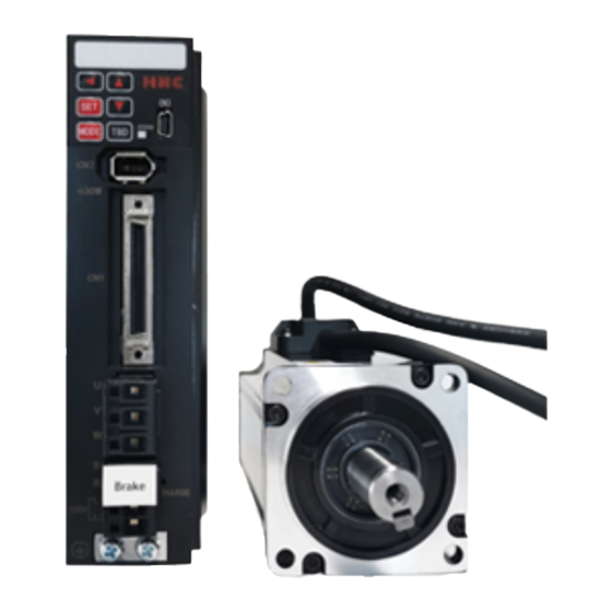
2) Servo drive 1.2 Parts name of servo motor and drive Figure 1.1.4 Parts name of servo motor Figure 1.1.5 Parts name of servo drive... -
Page 9: Model Name Of Servo Drive And Motor
1.3 Model name of servo drive and motor Capacity Motor model Motor size Drive model Drive size SE□□□-2-□□□□□□-A1 (Flange installation size) Middle inertia R16M30 SV-E3P005A-A Frame A 100W Middle inertia 003M30 SV-E3P010A-A 200W Low inertia 006L30 SV-E3P020A-A High inertia 006H30 400W Low inertia 013L30... -
Page 10: Model Selection Of Peripheral Braking Resistor
If the regenerative resistor is needed, refer to the installation of regenerative resistor. The use of regenerative resistor cannot necessarily guarantee the performance. When heating temperature is too high, please increase the resistance, or the permissible power. 1.5 Selection of cables and connector accessories for HNC ELECTRIC products ● For 750W or less Items... -
Page 11: Product Specifications
● 1KW or more Items Usage Model name Remark Connector for drive and motor Power connector (CON-4P-M100A for 1KW or more) Power cable SV-E3-CAB-SE130-PWR-T-R50M Length: 0.5m SV-E3-CAB-SE130-PWR-T-1R5M Length: 1.5m SV-E3-CAB-SE130-PWR-T-3M Length: 3m SV-E3-CAB-SE130-PWR-T-5M Length:5m SV-E3-CAB-SE130-PWR-T-10M Length: 10m Brake connector SM10-AP2S-S-C (for 1KW or more) Encoder cable terminal SM-6P+SM10-SP10S-M-C (for 1KW or more) Encoder cable... - Page 12 Frequenc 0 ~ 400 0~333 0~300 0~250 y(Hz) Encoder feedback 17-bit serial incremental/ absolute encoder Control Input 8 points (24VDC, photocoupler insulation) Switched under control mode signal Output 8 points (24VDC, photocoupler insulation , open-collector circuit output) Switched under control mode Analog Input...
- Page 13 Analog input Speed Input voltage -10V to +10V (Maximum speed occurs at ±10V) command input Smoothing IIR filter, FIR filter Pulse output Output pulse Encoder position pulse is output in the following manner: signal format A-/B-phase orthogonal phase difference pulse and Z-phase pulse is output in EIA-422 differential format, Z-phase pulse is output through open collector Control input Servo ON, alarm reset, internal speed command –start 1 &2, internal speed...
- Page 14 1. Use SELV power. ※SELV power: Safety Extra Low Voltage Reinforced insulation is needed for safety extra low voltage, non-dangerous voltage and dangerous voltage As the overcurrent protection for drive failure, please select the power supply of 100W or less. Current consumption is the value of I/O signal without the connection of servo ON.
- Page 15 Note 6) Ambient temperature for 2kW drive(Model name: SV-E3) 2.1.2 Overload detection characteristics For SV-E3 series servo drives, when the motor torque exceeds the torque values in the overload detection characteristics, overload protection will start which outputs overload alarm and the motor stops emergently.
-
Page 16: Motor Specifications
2.2 Motor specifications 2.2.1 Common specifications Table 2.2.1 Common specifications 200V~230V AC Items Unit Specifications Voltage 280VDC Model name 002M30 003M30 006L30 006H30 013L30 013H30 (SE□□-2-□□□□□□-□□) Middle Middle Middle High High inertia inertia inertia inertia inertia inertia Flange installation size □40 □40 □60... - Page 17 Rated power Without kW/s 13.6 23.9 58.7 23.5 change rate brake With brake 12.3 19.5 51.9 22.4 Mechanical Without 2.60 1.69 1.12 2.87 2.60 1.66 time constant brake With brake 3.06 1.87 1.37 3.12 0.75 1.75 Electrical time constant 0.64 0.76 1.99 2.47...
- Page 18 200V~230V AC Items Unit Spec. Voltage 280VDC Model name 024L30 024H30 048M20 048H20 072M20 075H20 095M20 (SE□□-2-□□□□□□-□□) High Middle High Middle High Middle inertia inertia inertia inertia inertia inertia inertia Flange installation size □80 □130 Mass Without brake With 10.4 brake Rated output 1000...
- Page 19 Power supply SELV power, reinforced insulation should be performed from the dangerous voltage. Rated voltage DC24V±10% Rated current Static friction torque N·m 2.39 or more 9.55 or more Absorption time Release time Release voltage 1VDC or more Rated time Continuous Ambient temperature for 0~40℃(Without condensation) 20~85%RH(Without condensation)
- Page 20 Permissible load Unit 100W 200W 400W 750W 1.5kW Permissible radial load Permissible axial load 2.2.3 N-T characteristics Figure 2.2.2 N-T characteristics...
- Page 22 2.2.4 Encoder specifications Table 2.2.3 Encoder specifications Items Description Remarks Motor Model Name SE□□-2-□□□□□□-I1(17 SE□□-2-□□□□□□-A1(17 bit) bit) Power supply voltage VCC DC 4.5V~5.5V Ripple voltage 5% or less External power supply BAT DC 2.4V~5.5V DC 2.4V~5.5V External capacitor CAP Current consumption 160mA(Typ.) Inrush current are excluded.
- Page 23 ※When the brake voltage is under 12V or use under the reverse polarity, single revolution accuracy decreases. 2.2.5 About oil seal Please use oil seal to prevent the entry of oil into the servo motor via the output shaft when using motor with gear box. All the SV-E3 series motors are installed with the oil seal.
-
Page 24: Installation And Size Of Servo Motor And Drive
3.1 Installation environment conditions About the environmental conditions, make sure to follow the company’s instructions. If you need to use the product outside the scope of the environmental conditions, please consult HNC ELECTRIC Corporation in advance. Keep it away from the direct sunlight. -
Page 26: Dimensions Of Servo Motor
●Install the drives in the vertical direction. Please use two M5 screws to fix the drive, master drive and slave drive respectively which is less than 800W Please use three M5 screws to fix the drive and master drive respectively which is more than 1kW. -
Page 30: Dimensions Of Servo Drive
3.5 Dimensions of servo drive (Same dimensions for SV-E3) -
Page 31: Wiring Explanation For Servo Motor And Drive
4. Wiring explanation for servo motor and drive 4.1 Wiring diagram 4.1.1 Wiring diagram [Points for correct wiring] ※ 24VDC and 200VAC input (main circuit) power supply should be wired from the same 200VAC main power supply. ※ Do not access switch between 24VDC power supply and drive. If you need switch, put it on the 200VAC cable of 24VDC input power supply. - Page 32 ① Please note that there is high voltage in the solid line of wiring diagram when wiring and using. ② The broken lines in the wiring diagram indicates the non-dangerous voltage circuit. 4.1.2 Connection of servo drive and motor Items Description Peripheral device Conform to European EC Directive.
-
Page 33: Drive Connector And Pins Arrangement
4.2 Drive connector and pins arrangement 4.2.1 Drive connector terminal Figure 4.2.1 750W or less Drive connector terminal Table 4.2.1 Terminal arrangement of drive connector/ SV-E3P 750W or less Name Symbol Pin No. Signal name Contents Regenerative B1/B2/L1 P interface of regenerative resistor resistance connection N interface of regenerative resistor Single-phase 200VAC... - Page 34 USB data+ USB signal grounding External fan CN14 24V for external fan GND for external fan User I/O Refer to “Chapter 8 Operation” Figure 4.2.2 1KW or more Drive connector terminal Table 4.2.2 Terminal arrangement of drive connector/ SV-E3P1KW or more Name Symbol Pin No.
-
Page 35: Terminal Arrangement And Wiring Color Of Motor Connector
Encoder signal: data input/output Encoder signal: data input/output Connect SHIELD to the connector housing PC communication VBUS USB power supply USB data- USB data+ USB signal grounding User I/O Refer to “Chapter 8 Operation” 4.3 Terminal arrangement and wiring color of motor connector 4.3.1 Motor connector and pins arrangement (750W or less) Figure: 4.3.1 Motor connector and pins arrangement Table 4.3.1 Cable list (For motor of 750W or less) - Page 36 input Motor power V phase White Motor power W phase Black Motor housing grounding Green Brake BRK+ Brake power supply 24VDC Yellow (※ 1) BRK- Brake power supply GND Blue Encoder(incr emental) Serial communication data + data White (red point) Serial communication data - data White (black point) Encoder power supply 5V...
-
Page 37: Communication Wiring Description
Name Signal Contents Remark name Motor power Motor power U phase input Motor power V phase Motor power W phase Motor housing grounding Brake BRK1 Brake power supply 24VDC (※ 1) BRK2 Brake power supply GND Encoder(incr Encoder power supply 5V output emental) Signal ground Serial communication data + data... - Page 38 Communication speed 57.6 kbps Data bit 8 bit Peer bit None Stop bit 1 bit Alarm detection CRC16-CCITT Transmission data 8 bit binary Data length 35 bytes or less L1= 5m(max) The wiring length between the upper controller and drive CN1 should be 5m or less. L2=250mm(max) The wiring length between each drives CN1 should be 250mm or less.
-
Page 39: Panel Display And Operation
[Setting method by set panel] ①Press the MODE button three times from the initial display status. The leftmost display on the LCD (6 digits) is [P] to come to the parameter setting mode. There is 3 digits, the point(.) and 1 digit on the right side of [P]. And the rightmost display is blank or [r]. -
Page 40: Operation Mode Change
Item or value select/confirm Selected value (flicker) increase UP (long-press) Selected value (flicker) increase rapidly DOWN Selected value(flicker) decrease DOWN(long-press) Selected value(flicker) decrease rapidly SHIFT Selected cursor moves left. SHIFT+DOWN The screen lock/unlock SHIFT+UP Reset the servo drive SHIFT+S, long press for The servo drive enabling ON/OFF 2s or more 5.3 Operation mode change... - Page 41 Figure 5.3.1...
-
Page 42: Status Display Mode
5.4 Status display mode The operation procedures of Status display mode are shown below. Press the “MODE” button twice from the beginning to get into status display mode and 「dP_St」 displays. Model code and serial number can be checked in this mode. Status mark number will be displayed on the right side of「St_」... - Page 43 Command pulse input (position)[pulse] To confirm the number of pulse from upper controller. Command pulse input (speed) Differential of Command pulse input (position) Less than 750W: [pulse/160μs], more than 1kW: [pulse/200μs] Analog command input(command value)[r/min] By adding input filter and gain, the analog speed command from upper control device can be regarded as input value of speed command.
- Page 44 Torque command[0.1%] The corresponding rated torque of 1000 is 100%, and corresponding rated torque of 3000 is 300%. Load ratio[digit] Permissible value is about 1000(load ratio 100[%]), overload error occurs when the load continuously exceed 1440s. Encoder/Rotor mechanical angle (1 rotation) [pulse] 1 rotation absolute angle data of rotor output by the encoder Encoder/Rotor mechanical angle (integrate) [pulse] Multi-rotation integrate angle data of rotor output by the encoder...
- Page 45 [About LCD display] The LCD can display the parameter of more than 6 digits and shows the following screens. Take the positive value 「123456789」and negative value 「-123456789」as example.. 1) Screen 1 Display lower 5 digits(lower) Positive Negative 2) Screen 2 Display upper 5 digits(middle) Positive Negative...
- Page 46 digital number is less than 6 even if it’s negative., [Parallel IO status] Display the control signal input (8 points) and output (8 points) status of I/O connector (CN1). The following table lists the signal name of I/O connector (CN1) and parallel IO status display. For the details of user I/O connector(CN1), refer to 「8.7.1 Signal description」...
- Page 47 [Regenerative status] Display main circuit DC power supply of drive and the working status of regenerative power circuit. When displays in the set panel, press SET button to show the following Figure 5.4.4 Table 5.4.4 Display list of regenerative status Display Name Description...
-
Page 48: Alarm Display Mode
in07 Reserved 『-』fixed Operating procedures of regenerative status are as follows. Press the “UP” or “DOWN” button, the number will be displayed alternatively. When input signal displays, press “SHIFT” button and it will shift to output signal 「ot00」 . When output signal displays, press “SHIFT” button and it will shift to input signal 「in00」... - Page 49 “MODE” button and the display can change from this mode to another, 「Err.**」 will display. For the remedies and reset method of alarm, refer to [9.2 Alarm disposal and reset]. Figure 5.5.1 Table 5.5.1 Alarm No. Alarm No. Alarm description Alarm No.
-
Page 50: Parameter Setting Mode
5.6 Parameter setting mode The operating procedures of parameter setting are shown below. When pressing “MODE” button three times from the initial display, 「P」 will be displayed on the leftmost of LCD and it comes to parameter setting mode. 3 digits, a decimal point, 1 digit and a blank will be displayed in turn on the right side of 「P」 . The combination of 3 digits, a decimal point and1 digit constitute the parameter No. -
Page 51: Auto Tuning Mode
5.7 Auto tuning mode Auto tuning mode includes 「Simple adjustment」 and 「Fine adjustment」. 「Simple adjustment」 Select gain level among 5, 10, 15, 20, 30 and then start auto tuning and setting automatically the expected inertia ratio to achieve the desired operation. Meanwhile, the inertia ratio can be set manually. The most suitable gain can be set corresponding to inertia ratio. - Page 52 Inertia condition P_GGLP / 113.1 Control gain setting P_GSET / 113.0 Inertia ratio P_inEr /102.0 conversion ratio of Inertia ratio P_inTr /104.0 Selection of real-time auto tuning P_TUEn /110.1 Control level P_CLEv /114.0 Integral gain P_inTE /119.0 First gain FF compensation P_GFF1/117.0 Second gain FF compensation P_GFF2/118.0...
-
Page 53: Parameter Saving Mode
5.8 Parameter saving mode 「SAVE_P」(Parameter saving mode) will be displayed on the panel if pressing ‘MODE” button six times from the beginning. The new parameters, set in Parameter setting and auto tuning mode, can be written to EEPROM in the parameter saving... -
Page 54: Auxiliary Function
mode. Please note that the newly-set parameters, which have been set in Parameter setting and auto tuning mode but not saved to EEPROM, will disappear and return to the value before after power-off. The operating procedures of saving parameters are shown below. Figure 5.8.1 Parameter saving mode In parameter setting mode when change the parameters that need restarting 24VDC control power supply, please restart the control power supply after the above procedures done. - Page 55 5.9.1 Drive connector terminal description JOG function is function for test run without the commands output by the upper controller. Please use the test run function for the purpose of adjustment. For details. Working conditions for JOG function ・ The JOG function is available in the pulse command modes of position control and speed control mode. Control the machines according to the corresponding gain of control modes.
- Page 56 The motor rotates when pressing the button, and stops as releasing the button. 7. Make the servo OFF by I/O and shows to end the JOG operation. Then press MODE button and show , which means the operation status changes from JOG to the general. If the servo is ON, the operation cannot change from JOG operation to general operation status and the alarm will occur.
-
Page 57: Parameter Description
Figure 5.9.3 5.9.3 Encoder clearing function For details, please refer to [Reference SV-E3 series absolute system]. 6. Parameter Description 6.1 Parameter list This section gives a detailed description of the displayed parameters on the panel. The column of 「No.」is the parameter number. Two numbers separated by “/” are the numerator and denominator number of parameters. - Page 58 No.116.0 Control gain 2 (Position control mode) No.117.0 Gain FF compensation 1(Position control mode) No.118.0 Gain FF compensation 2(Position control mode) No.119.0 Integral gain(Position control mode) No.131.0 Control gain 1(Speed control mode) No.132.0 Gain FF compensation 1(Speed control mode) No.133.0 Integral gain(Speed control mode)...
- Page 59 Keep position deviation counting 67.3 Deceleration stop Method 224.0 Release condition 224.1 Operation time 226.0 Cancel deceleration stop 227.0 Power supply error Switch 224.2 Operation time 228.0 Torque command range 151.0 Adjustment Inertia ratio 102.0 Damping ratio 103.0 Auto tuning Mode switch 110.0 Project...
- Page 60 Smoothing filter 1 average moving times 81. 0 *1) The marking method varies from the drive version. The version of 3. 5. 1. 0 or before is marked with [Selection of position command smoothing filter 1] *2) The marking method varies from the drive version. The version of 3. 5. 1. 0 or before is marked with [Selection of position command smoothing filter 2] Types Names...
- Page 61 Time 659. 0 Torque limit Switch 647. 0 Value 656. 0 Home position return Press detection time 655. 0 Creep switch 647. 1 Operation speed 648. 0 Creep speed 649. 0 Acceleration/deceleration time 650. 0 Home position travel distance 651. 0 Home position data 653.
- Page 62 Speed limit 152. 0 Table 6.1.2 Parameter list Parameter Contents Whether to restart control power supply 002.0r [Basic setting] Control mode selection. Control mode Note) Do not change when servo is ON. 0= Position control mode 1= Speed control mode 2= Torque control mode [Initial value] 0 (Position control mode) [Setting range] 0 to 2...
- Page 63 response time [Setting range] 0 to 255 032.0r [Basic setting] Select pulse signal type of pulse command input. Pulse train 0= Pulse and direction: using pulse and direction input command 1= Orthogonal phase difference: using orthogonal phase pulse (A-phase/B-phase) input mode input 2= CCW/CW: using positive pulse and negative pulse [Initial value] 0 (Pulse/direction)
- Page 64 When the input frequency is high, please set the small passing pulse width. To improve interference immunity, please set the large passing pulse width. [Initial setting] 4 (Passing pulse width is 150ns or less) [Setting range] 0 to 15 034.0r [Basic setting] Set the parameters of position command pulse division/ multiplication.
- Page 65 upper controller. [Initial setting] (Numerator / Denominator )=1000/1000 [Setting range] 0~65535/1~65535 052.0 / [Basic setting] Analog speed command CCW speed limit threshold value. 053.0 Analog speed Analog command CCW speed limit = (the highest speed of motor) * (threshold command CCW value(numerator))/ (threshold value(denominator)) speed limit [initial setting] (Numerator / Denominator )=5000/5000...
- Page 66 062.2 [Basic setting] Select offset adjustment of analog speed command. Select offset 0=Auto tuning adjustment type of 1=Manual tuning analog speed Auto tuning works under the voltage which corresponds to 0r/min of speed command command while servo ON. Manual tuning means input offset manually to make sure input voltage 0Vcorresponds to speed command 0r/min.
- Page 67 position command 0=Disable smoothing filter 1 1=Enable and position Command will be smooth as shown below after using a smoothing filter. command filter 2 [Adjustment method] Used when command acceleration or deceleration are too fast. Used to suppress device resonance when positioning. Measuring the resonant frequency in torque command curve and setting a corresponding average movement number in position command smoothing filter1 moving average time No,80 or position command smoothing filter2...
- Page 68 method at drive the following combination methods. restriction input 0=Free-run 1=Short brake 2= Prompt stop Combin Deceleration method Stopping method ation No.67.1 No.67.2 0: Free-run 0: Free-run 1: Short brake 0; Free-run 2: Prompt stop 1: zero clamp 2: Prompt stop 0: Free-run [Initial setting] 1 [Setting range] 0 to 2...
- Page 69 Positioning parameter is the speed limit for judging positioning completion. completion speed The setting value should be less than the number of speed limit of upper controller. [Initial value] 750W or less:2 [pulse/160μs] (±2 [pulse/160μs] ・・・ 5.72[r/min] 1kW or more : 2 [pulse/200μs] (±2 [pulse/200μs])・・・...
- Page 70 [Setting range] 0 or 1 078.0 [Adjustment] Set the average movement time of speed command smoothing filter. Average It can be used when No.77.0 is effective. movement time of [Initial value] 100 [ms] speed command [Setting range] 1 to 1000 smoothing filter 080.0r and [Adjustment]...
- Page 71 position shift will occur. [Initial value] Filter 1: 25 for 200~750W, 20 for 1k~2kW Filter 2: 10 for 200~750W, 10 for 1k~2kW [Setting range] 1 to 6250 for filter 1, 1 to 1250 for filter 2. 087.0 [Special setting] When set No.65.0 to “1(enable)”, it is valid to detect the position deviation errors. Position deviation Normally it’s effective.
- Page 72 inertia ratio 1=Standard mode 1=Unbalanced mode [Initial value] 1 (Standard mode) [Setting range] 1 to 2 110.1 [Adjustment] Select whether to use real-time auto tuning. With(out) the use 0 = Disable of real-time auto 1 = Enable and Apply Inertia ratio tuning 2 = Enable and Apply Inertia ratio and Dumping ratio [Initial value] 0 (Disable)
- Page 73 Gain FF mode. After confirming inertia ratio, adjusting this parameter will shorten the setting compensation 1 time. Too high setting value will lead to overshoot. And too low setting value will make (position control) setting time longer. [Initial value] 10000[0.01%] [Setting range] 0 to 15000 118.0 [Adjustment]...
- Page 74 gain(speed disturbance. control) [Initial value] 300[rad/s] [Setting range] 45 to 5000 144.0 [Basic setting] Select torque command limit value in No.147.0, No.148.0 With or without the Confirm the following items when using torque limit. use of torque ①「No.65.0 Selection of Position deviation error detection」, please set it to command limit “0=Disable”...
- Page 75 Selection of torque 0=No filter command 1= Preliminary IIR filter low-pass filter [Initial value] 1 (Preliminary IIR filter) [Setting range] 0 or 1 160.1 [Adjustment] Whether the notch filter is used to set the torque command. Torque command 0=Disable Selection of 1=Enable whether to use [Initial value] 0 (Disable)
- Page 76 at Servo off: 1 = Rotations of cancelation or operating time cancelation [Initial value] 1 (Rotations of cancelation or operating time) reasons [Setting range] 0 or 1 224.2 [Basic setting] Enable/Disable Deceleration Stop when the voltage from a control power supply drops Use of a by No.
- Page 77 [Initial value] 0 (Incremental system) [Setting range] 0 to 2 272.1r [Basic setting] Set the rotation direction of encoder output. Encoder output 0 = Down counting in the case of CCW rotation rotation direction 1 = Up counting in the case of CCW rotation [Initial value] 1 (Up counting in the case of CCW rotation) [Setting range] 0 or 1 276.0r /...
- Page 78 Override [Setting range] 0 to 65535/1 to 65535 (Denominator/ Numerator) 294. 0/ [Basic setting] Set Analog torque command CW torque limit Override 295. 0 Analog torque Analog command CW torque limit =motor peak torque × (Override command CW (Numerator)/Override(Denominator)) torque limit [Initial value] (Numerator) / (Denominator) = 3100/3100 (Varies with motor models) Override [Setting range] 0 to 65535/1 to 65535...
- Page 79 [Initial value] 1000[ms] [Setting range] 0 to 60000[ms] 387. 0 [Basic setting] Set a target speed of the JOG operation. JOG operation: [Initial value] 300[ r/mi n] Target speed [Setting range] For 50W~100W:0~6300[ r/mi n] For 200W~400W:0~5000[ r/mi n] For 750W: 4500[ r/mi n] For 1kW~2kW:0~3000[ r/mi n] Note) Alarm occurs when it exceeds max.
- Page 80 Target speed 8 Short circuited Short circuited Open Open Open Short circuited Short circuited Open Short circuited Open Short circuited Short circuited Short circuited Short circuited Short circuited [Initial value] Target speed 1: 500 [r/min] Target speed 2: 1000 [r/min] Target speed 3: 1500 [r/min] Target speed 4: 2000 [r/min]...
- Page 81 645. 0 [Special setting] Select Base signal 1 at determine Home position. Base signal 1 0 = Arbitrary position selection for Home 1 = Stopper position 2 = Home position DOG front end [Initial value] 2 (Home position DOG front end) [Setting range] 0 to 2 645.
- Page 82 [Initial value] 0 (Disable) [Setting range] 0 to 1 647. 1 [Basic setting] Select “ 1= Move” from home position base signal 1 detection to home position Action at home completion. position return 0 = No move completion 1 = Move [Initial value] 0 (No move) [Setting range] 0 to 1 648.
-
Page 83: Parameter List For Point Table
659. 0 [Special setting] Set Home position return Timeout Time. Home position [Initial value] 60,000[10ms] return Timeout [Setting range] 0 to 60,000 Time 6.2 Parameter list for point table Table 6.2.1 Parameter list for point table Point Position Rotation Acceleration Deceleration Command Dwell... -
Page 84: Servo Off→On
Note 1) About I/O status, “C” indicates the internal output circuit contact or external contact is close, while “O” means open. Note 2) After the parameters are cleared, 5sec is needed for T1 because of parameter initialization. Note 3) When /ERROR and main circuit power supply PRDY is ON, S-RDY is ON. 7.2 Servo OFF→ON Note 1) About I/O status, “C”... -
Page 85: Servo Stop
7.3 Servo stop 7. 3. 1 Servo ON→OFF(motor stops) When servo OFF, the deceleration stop release condition is to reach the speed release, or after specified running time(Parameter No.224.0=1, initial setting) , the motor speed is below the servo OFF deceleration stop release speed (Parameter No.227.0=50rpm, initial setting). -
Page 86: At Occurrence Of Alarm
Note 1) About I/O status, “C” indicates the internal output circuit contact and external contact is close, while “O” means open. Note 2) When servo OFF, it stops in the selected deceleration stop mode(Parameter No.224.0).. Note 3) Immediate stop and short-circuit brake will finish when it meets the conditions of deceleration stop at servo OFF (ParameterNo.224.1, 226.0, 227.0) Note 4) MBRK will be OFF when the deceleration stop has completed or the motor speed is to reach the setting value specified in parameter No.227.0. - Page 87 Note 1) About I/O status, “C” indicates the internal output circuit contact and external contact is close, while “O” means open. Note 2) At servo OFF, via type selection, the deceleration stop (parameter No.224.0) will be:. a) Prompt stop or short brake via short brake deceleration stop b) Free run, free run stop Note 3) Deceleration stop will finish when it meets the conditions of deceleration stop at servo OFF (parameter No.224.1, 226.0, 227.0) .
-
Page 88: Alarm Reset
7.5 Alarm reset 7.5.1 Alarm reset (SVON=ON) Figure 7.5.1 Alarm reset (SVON=ON) Note 1) About I/O status, “C” indicates the internal output circuit contact and external contact is close, while “O” means open. Note 2) The servo can be not ON when motor speed is less than 30rpm. Note 3) T1 can be set in parameter No.238.0.(Initial value 4msec, value range: 0 to 500msec) 7.5.2 Alarm reset (SVON=OFF) Figure 7.5.2 Alarm reset (SVON=OFF) -
Page 89: Operation
Note 1) About I/O status, “C” indicates the internal output circuit contact and external contact is close, while “O” means open. 8. Operation 8.1 Preface 8.1.1 Preface This product can drive the motor by 5 operation modes of combination of control mode and command mode. This chapter describes the operation method of different operation modes. - Page 90 ■ Torque control mode (Analog torque command input) 1) Wiring for user I/O (CN1) connector 2) The setting of basic parameter 3) Test run ■ Position control mode (Internal position command) 8.1.2 Precautions Table 8.1.1 Precautions Make sure to cut off all phases of power supply To .prevent electric shock, fire, malfunction and injury before wiring.
- Page 91 Delay time 89. 0 Speed deviation Switch 65. 1 Value 90. 0 Delay time 91. 0 Encoder pulse output Frequency upper limit 285. 0 Delay time 286. 0 Instantaneous Delay time 305. 0 voltage-drop Drive restriction Setting 67. 0 options Deceleration method 67.
-
Page 92: Position Control Mode (Pulse Position Command Input)
Return to the display to change the parameter No. (Display parameter 2.0) Press UP button to change the parameter No. Press button Display parameter 3.0. Display the setting value of parameter 3.0. Press button once Press button to set the related parameters. We can go to the next step after all the parameters are set. Switch to the mode of setting panel. - Page 93 Reserved T-LIMIT Torque limit output Encoder Z-phase output (open collector) SRDY+ Servo ready output + SRDY- Servo ready output - ALM+ Servo alarm output+ ALM- Servo alarm output- Reserved (Disconnected) Reserved Reserved CMD_PLS Pulse command, pulse, orthogonal phase difference A-phase, CCW /CMD_PLS Pulse command, /pulse, orthogonal phase difference /A-phase, /CCW...
- Page 94 Reserved Reserved Note 1)Control power supply(24V, G24V) and I/O power (COM+, COM-) share the same power supply(For the models of 750W or less). Note 2)If there is drive inductive load(relay), please use protective circuits(diode). Note 3) Transistor output is an open collector output circuit of the Darlington-connected. It should be connected with relay or optocoupler.
- Page 95 division and multiplication No.276.0, 278.0 or reduce the speed to increase the pulse width.[Pulse width]=1/speed/(division and multiplication×2 8.2.2 Pulse position command input (24V open collector input) Name Symbol Terminal Signal name Contents User I/O Drive control power supply 24V input ●24V power G24V Drive control power supply GND...
- Page 96 Reserved Reserved Reserved Reserved OUT_A Encoder A phase output /OUT_A Encoder /A phase output OUT_B Encoder B phase output /OUT_B Encoder /B phase output OUT_Z Encoder Z phase output /OUT_Z Encoder /Z phase output Signal ground RS-485 communication data /485 RS-485 communication /data Signal ground Reserved(Disconnected)
- Page 97 Note 1)Control power supply(24V, G24V) and I/O power (COM+, COM-) share the same power supply(For the models of 750W or less). Note 2)If there is drive inductive load(relay), please use protective circuits(diode). Note 3) Transistor output is an open collector output circuit of the Darlington-connected. It should be connected with relay or optocoupler.
- Page 98 Name Symbol Terminal Signal name Contents User I/O Drive control power supply 24V input ●24V power G24V Drive control power supply GND supply input COM+/- I/O power supply 24V input ●Parallel I/O SVON Servo ON input ●Pulse command RESET Alarm reset input input HOLD Command input restriction...
- Page 99 Reserved Reserved OUT_A Encoder A phase output /OUT_A Encoder /A phase output OUT_B Encoder B phase output /OUT_B Encoder /B phase output OUT_Z Encoder Z phase output /OUT_Z Encoder /Z phase output Signal ground RS-485 communication data /485 RS-485 communication /data Signal ground Reserved(Disconnected) Reserved...
- Page 100 Note 1)Control power supply(24V, G24V) and I/O power (COM+, COM-) share the same power supply(For the models of 750W or less). Note 2)If there is drive inductive load(relay), please use protective circuits(diode). Note 3) Transistor output is an open collector output circuit of the Darlington-connected. It should be connected with relay or optocoupler.
- Page 101 The factory setting is 「Pulse position command input」. It is necessary to set the following parameters if the drive is driven by pulse position command input. Table 8.2.4 Parameter of control mode (Pulse position command input) Parameter No. Parameter Operation · Value Control mode selection Set to “0”.
- Page 102 69.0 Positioning completion speed 70.0 Positioning completion Pulse train command input (speed) 71.0 Positioning completion Detection delay time 66.0 Position command smoothing filter 1 selection Set the damping filter. Suppress the resonance of device when the 66.1 Position command smoothing filter 2 selection acceleration/ deceleration command is too high or 80.0 Position command smoothing filter 1 Moving...
-
Page 103: Speed Control Mode (Analog Speed Command Input)
a low speed(100r/min). Make sure the rotation direction of the motor is same to the setting direction. Improve the position command pulse frequency gradually after confirming the safe implementation of actual operation. Then confirm the operation until it comes to the specified speed. Note1: The control power supply for the models of 750W or less are supplied by external 24V DC. - Page 104 Reserved Reserved Reserved Reserved A SPEED Analog speed command input A_GND Analog speed command input ground Reserved Reserved OUT_A Encoder A phase output /OUT_A Encoder /A phase output OUT_B Encoder B phase output /OUT_B Encoder /B phase output OUT_Z Encoder Z phase output /OUT_Z Encoder /Z phase output Signal ground...
- Page 105 Note 1)Control power supply(24V, G24V) and I/O power (COM+, COM-) share the same power supply(For the models of 750W or less). Note 2)If there is drive inductive load(relay), please use protective circuits(diode). Note 3) Transistor output is an open collector output circuit of the Darlington-connected. It should be connected with relay or optocoupler.
- Page 106 Set the basic parameters. The following parameters must be set if the drive needs to be driven by analog speed command input. Table 8.3.2 Parameter of control mode change(Analog speed command input) Parameter No. Parameter Description Select control mode. Set to “1”. Select command mode.
- Page 107 Table 8.3.5 Analog speed command Speed limit value settings Rotation direction Parameter No. Parameter Setting value 52.0 Analog speed command “3000” CCW speed limit value(Numerator) 53.0 Analog speed command “5000” CCW speed limit value(Denominator) 54.0 Analog speed command “3000” CW speed limit value(Numerator) 55.0 Analog speed command “5000”...
-
Page 108: Speed Control Mode (Internal Speed Command)
actual operation. Then confirm the operation until it comes to the specified speed. Note1: The control power supply for the models of 750W or less are supplied by external 24V DC. 1kW or more are supplied from internal. So the control power supply of models of 1kW or more can be ON or OFF by switching on or cutting off the main circuit AC power. - Page 109 Reserved Reserved Reserved Reserved Reserved Reserved Reserved Reserved Reserved OUT_A Encoder A phase output /OUT_A Encoder /A phase output OUT_B Encoder B phase output /OUT_B Encoder /B phase output OUT_Z Encoder Z phase output /OUT_Z Encoder /Z phase output Signal ground EIA-485 communication data /485 EIA-485 communication /data...
- Page 110 Note 1)Control power supply(24V, G24V) and I/O power (COM+, COM-) share the same power supply(For the models of 750W or less). Note 2)If there is drive inductive load(relay), please use protective circuits(diode). Note 3) Transistor output is an open collector output circuit of the Darlington-connected. It should be connected with relay or optocoupler.
- Page 111 Set the basic parameters. The following parameters must be set if the drive needs to be driven by internal speed command. Table 8.4.2 Parameters of control mode change (Internal speed command) Parameter No. Parameter Description Select control mode Set to “1”. Select command mode Set to “3”.
-
Page 112: Torque Control Mode (Analog Torque Command Input)
Switch on the main circuit power to the drive(200V AC). Make the SVON input of drive ON to start the motor excitation. (Connect the I 1 terminal to the COM-) Select the target speed according to the ON/OFF combination of I 5(VCSEL1),I 6(VCSEL2)and I 7 (VCSEL3). - Page 113 input HOLD Command input restriction(Zero speed clamp) ●Analog input Reserved ●ABZ output Reserved CCWL CCW drive input restriction CW drive input restriction TLSEL1 Torque limit input COM- I/O power supply GND MBRK Brake release output SERVO Servo status output Reserved Reserved T-LIMIT Torque limit output...
- Page 114 EIA-485 communication data /485 EIA-485 communication /data Signal ground Reserved(Disconnected) Reserved Reserved Reserved Reserved Note 1)Control power supply(24V, G24V) and I/O power (COM+, COM-) share the same power supply(For the models of 750W or less). Note 2)If there is drive inductive load(relay), please use protective circuits(diode). Note 3) Transistor output is an open collector output circuit of the Darlington-connected.
- Page 115 optocoupler. Please don’t connect transistor directly because the voltage VCE(SAT) between collector and emitter is about 1V which cannot meet the required voltage VIL of TTL IC when transistor is ON. Note 4) Terminal resistance must be connected as shown in the wiring diagram. Note 5) Terminal resistance must be connected as shown in the wiring diagram.
- Page 116 Example) Make the following settings if the motor with the maximum torque of 3000 [0.1%] needs to set to 1000 [0.1%] at the maximum command input voltage (±10V). Table 8.5.4 Analog torque command input filter settings Parameter No. Parameter Setting value 288.0 Analog torque command Input filter constant (Numerator) “1000”...
-
Page 117: Position Control Mode(Internal Position Command)
Drive the motor after release the brake on the motor if If not, it may cause the malfunction to the brake and the motor is attached with the brake. motor. ■Test run Table 8.5.8 Steps for test run (Analog torque command input) Steps Operation Make sure all the wiring are connected properly. -
Page 118: Description Of User I/O Connector (Cn1) Terminal Arrangements
Note 1) The home position in the drive may disappear sometimes. Please reset the home position after parameter setting. 2) Please set 「Selection of Auto interpolation for command division and multiplication」(Parameter No.32.2) to “1=Enable”. Initial value is “1=Enable”. When “0=Disable” is set, the speed change will become large. 8.7 Description of User I/O connector (CN1) terminal arrangements Figure 8.7.1 Terminal arrangements Figure 8.7.2 Connector... - Page 119 I7 input Comma Pulse train Internal Analog Internal Analog I8 input command regeneration command regeneration command mode command command SVON RESET RESET/PCLR RESET RESET RESET HOLD PCSTART1 HOLD VCRUIN1 HOLD PCLR PCSEL1 (Reserved) VCRUIN2 (Reserved) (Reserved) PCSEL2 (Reserved) VCS L1 (Reserved) PC EL3 CCWL...
- Page 120 ②Orthogonal phase ②Input B phase of AB phase orthogonal phase difference pulse signal from host control difference B phase device(differential input) ③CCW+CW pulse CW ③Input CCW+CW of CW pulse from host control device (differential input) [5V open collector circuit] [5V open collector circuit] Max. command pulse frequency 200kpps ④5V power supply input of ④5V power supply input terminal of /CMD_DIR.
- Page 121 CC-D( [5V open collector input] [5V open collector input] Max. pulse frequency 200kpps ①5V for /CMD_DIR ①5V power input terminal of /CMD_DIR Built-in current limiting resistor Table 8.7.2 I/O input signal Signal Contents Function Control mode name ○ ○ ○ SVON Servo ON ●Servo is ON when connecting COM-.
- Page 122 Drive restriction is enabled 」. Initial value: 「1: Short brake」. ●After-stop state can be selected in parameter No.67.2 「Selection for Stop condition when Drive restriction is enabled」. Initial value: 「0: Free-run」 ●Parameter No.67.3 「Selection for Location deviation counter option when Drive restriction is enabled」can be set to hold the position deviation counter.
- Page 123 ●Polarity detection can be changed by parameter No.646.1 「Home position sensor input polarity」 . When the initial setting is to be connected to COM- and OFF, the home position sensor is detected. VCRUN1 Internal speed △ ●Enable when select “1=Trapezoid speed command” in parameter No.388.0. command start ●After connecting to COM-, the motor starts in CCW direction.
- Page 124 name O1 output ●Parallel I/O output ●O7+, O7-, O8+ and O8- is differential output. O2 output ●Function varies according to different control modes and command modes. For O3 output details, refer to the following table. O4 output Control Position control Speed control Torque O5 output...
- Page 125 Table 8.7.3 I/O output signal Signal Contents Function Control mode name ○ ○ ○ MBRK Brake release ●After the electromagnetic brake is released, the connection with COM- should is OFF. ○ ○ ○ SERVO Servo status ●When the servo is ON, the connection with COM- is OFF. ○...
-
Page 126: Adjustment
P: Position control mode, S: Speed control mode, T: Torque control mode indicates it can input signals 「○ 」 and 「 △」 in different control modes. 「 △」can switch signals according to command mode. For details, please refer to user I/O connector CN1 terminal arrangements for each command mode. - Page 127 2: Standard setting 3: Applicable for the device that needs to adjust the light load(emphasis on convergence) Table 8.8.2 The correspondence between the setting value of inertia condition and characteristics Setting value Stability of the corresponding load change Convergence rate Position deviation at constant speed Strong Slow...
- Page 128 circuit AC power. By set panel ■ Table 8.8.4 Auto tuning (By set panel) Display and operation Description Initial display. Switch to the set panel. Press for five times Switch to the auto tuning mode Enter into the auto tuning mode Press once Press...
- Page 129 button to set (from flicker to ON). Points to note To get the desired response, set the control gain level again. Auto tuning completed and switch to the set panel mode. Press twice Switch to parameter saving mode. The parameter is stored to EEPROM. ([P] in [SAVE_P] will flicker.) Press once Normal completion.
- Page 130 Figure 8.8.4 Position deviation convergence difference set by integral gain ③Gain FF compensation 1 adjustment The adjustment method of Gain FF compensation 1(Position control) No.117.0 is shown below. If the Gain FF compensation 1 is higher, the setting time is shorter. But if too high, overshoot may occur. Please adjust it to the required response in the absence of overshoot.
- Page 131 the position deviation will be on the negative side(over compensation). If set the bigger value at lower resolution, the operation noise will become louder. If the position deviation in the operation has no any other problems, the setting value can be 0. Figure 8.8.6 Position deviation convergence difference set by Gain FF compensation 2 8.8.3 Vibration reduction adjustment ①Vibration reduction methods for smoothing filter...
-
Page 132: Home Position Return
the vibration occurs. When the gap is too big, even if setting the notch filter, the resonance cannot be suppressed completely. At this time, increase the [Torque command Notch filter depth selection(No.170.0)] to get the shallower filter performance. When multiple notch frequency exist, increase the [Torque command Notch filter width selection(No.169.0)] to widen the notch frequency. - Page 133 For the wiring and basic parameter setting, refer to [Appendix 2 SV-E3 Positioner function]. In home position return, there are Arbitrary position, Stopper and Home position DOG front end and used in the situation of ■ selection of Z-phase as the base signal. The home position return can be started by user I/O input.
- Page 134 Figure 8.9.2 3) Home position DOG front end (home position sensor) Use the following parameter items in the box when use the Home position DOG front end. For the details of parameters, refer to [8.9.4 Parameter description]. For the examples of parameter setting method, refer to [8.9.8 Parameter description for home position return]. Figure 8.9.3 8.9.4 Parameter description The home position return can be done by the combination of parameter setting.
- Page 135 ・ No. 645. 1: Base signal 2 selection for Home position ・ No. 645. 3: Home position Base signal 1 redetection ・ No. 646. 0: Home position return direction ・ No. 647. 1: Action at home position return completion Name Unit 645.
- Page 136 Figure 8.9.4 Home position Base signal 1 redetection Name Unit 646.0 Home position return direction Set Home position return base signal 1 direction 0 = CCW [Initial value] 1 = CW 1) Under the condition that home position base signal 1 is “Arbitrary position”. When set the Base signal 2 selection for Home position to “1=Encoder Phase Z”, the operation direction of Encoder Phase Z can be detected, that is the home position base signal moves in the direction of home position travel distance.
- Page 137 Figure 8.9.6 Home position return direction (Stopper) 3) Under the condition that home position base signal 1 is “Home position DOG frond end ”. Set the direction from Home position DOG sensor front to Home position DOG front end. If the start point of home position return is in the front of home position DOG sensor, it is the operation direction after home position return starts.
- Page 138 Selecting “0”, detect the home position sensor at open-circuit between ORG and COM-. Selecting “1”, detect the home position sensor at closed-circuit between ORG and COM-. Figure 8.9.8 Home position sensor input polarity Name Unit 646.2 Home positon return Timeout option Enable/Disable Home position return Timeout.
- Page 139 completed. When selecting “Move”, after detecting the base signal for home position, deceleration to stop and perform the positioning operation according to the parameter set. Name Unit 648.0 Home position return Speed Set Home position return Speed. [Setting range] 1 to max. speed of the motor [Initial value] 500 Figure 8.9.9 Home position return Speed Name...
- Page 140 651.0 Home position return Home position data Command unit(Note 1) Set a position at the time of home position return complete. When home position return is completed, change the setting value to ABS position feedback of home position return. [Setting range] -1, 000, 000, 000~1, 000, 000, 000 [Initial value] 0 [command unit] Name Unit...
- Page 141 1)PCSTART1 CW start(6 pins) ・Use PCSTART1(6 pins) to start home position return ・Specify “0” to the Point No. in PCSEL1. . . 4 in user I/O, the PCSTART1 changes from open-circuit to closed-circuit to start the home position return. 2) PCSEL1. . . 4 point No. selection(7~10 pins) ・Set 「Point No.0 function selection」...
- Page 142 b) Interrupted before HEND becomes ON in the home position return The home position return interrupts in the following situations; ○Make the servo OFF in the home position return with the operation ○Perform the deviation counter clearing in the home position return with the operation ○Input the drive restriction and perform the deviation counter clearing in the home position return with the operation ○Alarms occur and servo OFF in the home position return with the operation c) “Incremental system”...
- Page 143 2) When set the Action at home position return completion(No. 647. 1) to “0= No move” After the base signal for home position is detected, it will decelerate to stop and HEND is ON at home position return completion. Then do not shift to the home position return. The action will be completed at the position of deceleration stop and output MEND to be ON.
- Page 144 When performing the deviation counter clearing, it will emergency stop. ■Input the drive restriction, then perform the deviation counter clearing. 5) Set the 「Selection of Auto interpolation for command division and multiplication」(No. 32. 2) to “1: Enable”. The initial value is “1: Enable”.
- Page 145 Note 2) Timing chart with no I/O input. The start will delay if vibration occurs. Note 3) The start time varies from the different conditions. Table 8.9.2 Operation procedures for home position return at servo ON Items Description Parameter setting for Set the parameter of home position return speed, home position return creep home position return speed, home position return acceleration/deceleration time.
- Page 146 Table 8.9.5 Example for Parameters of home position return with arbitrary position Parameter name Setting description 646. 0 Home position return direction 0=CCW 647. 1 Action at home position return 1=Move completion 1) When not to use Encoder phase Z Set “Base signal 2 selection for Home position”...
- Page 147 Figure 8.9.20 Overview diagram with horizontal axis(home position return with arbitrary position, encoder phase Z) Note) ) I/O state: “C” indicates the closed-circuit for internal output circuit contact or external contact. “O” indicates open-circuit. Figure 8.9.21 Timing chart ((home position return with arbitrary position, Encoder phase Z) ・When set the Action at home position return completion(No.
- Page 148 Table 8.9.7 Parameters for home position return with stopper Parameters Setting 645. 0 Base signal 1 selection for Home Set to “1 = Stopper” position 645. 1 Base signal 2 selection for Home Set the Encoder phase Z to the base signal for home position after position detecting Base signal 1 646.
- Page 149 Note) ) I/O state: “C” indicates the closed-circuit for internal output circuit contact or external contact. “O” indicates open-circuit. Figure 8.9.23 Timing chart ((home position return with stopper) ・When set the Action at home position return completion(No. 647. 1) to “No move”, it will not shift to the home position and end the action.
- Page 150 Figure 8.9.24 Overview diagram with horizontal axis(home position return with stopper and encoder phase Z) Note) ) I/O state: “C” indicates the closed-circuit for internal output circuit contact or external contact. “O” indicates open-circuit. Figure 8.9.25 Timing chart ((home position return with stopper and encoder phase Z) ・When set the Action at home position return completion(No.
- Page 151 ・The home position return completed when confirm the position according to the stop position from outputting torque limit to pressing detection time (No. 655. 0). C) Home position return with Home position DOG front end Home position return with the Home position DOG front end or Encoder phase Z near the Home position DOG front end. ■...
- Page 152 Figure 8.9.26 Overview diagram with horizontal axis(home position return with Home position DOG front end) Note) ) I/O state: “C” indicates the closed-circuit for internal output circuit contact or external contact. “O” indicates open-circuit. Figure 8.9.27 Timing chart ((home position return with Home position DOG front end) ・When set the Action at home position return completion(No.
- Page 153 Figure 8.9.28 Overview diagram with horizontal axis(home position return with Home position DOG front end and phase Z) Note) ) I/O state: “C” indicates the closed-circuit for internal output circuit contact or external contact. “O” indicates open-circuit. Figure 8.9.29 Timing chart ((home position return with Home position DOG front end and phase Z) ・When set the Action at home position return completion(No.
-
Page 154: Troubleshooting And Countermeasures
When the alarm occurs, the alarm description can be confirmed according to the alarm code on the panel of servo drive. The alarm code and alarm description are shown in the 「Warning list」. If you want to consult with HNC ELECTRIC Corporation, make a record of the alarm and contact with us. 9.2 Alarm handling and alarm reset For alarm handling and resetting, please refer to “Warning List”. - Page 155 ・ The combination of motor and drive is ・ Please Check the encoder cable. power supply incorrect. ・ The encoder cable does not connect to the drive correctly.(including disconnect). Overspeed error ・ Motor rotates exceeding the max. speed ・ Please adjust the parameters. Reset Inappropriate command...
- Page 156 Encoder pulse ・ Encoder pulse output frequency exceeds ・ Check the value of Encoder pulse output Division Restart control output frequency 4Mpps and multiplication(No.276.0, No.278.0) power supply error ・ Check the encoder pulse output frequency upper limit value(No.285.0) and error detection delay time (No.286.0) Internal positon...
- Page 157 (data receive) time ・ Use the cable at a length of less than 20m power supply ・ Check the disturbance by the noise Encoder error (No ・ Encoder communication interrupts -Use shielded twisted pair cable response) -Separate encoder cable from the power cable Encoder error ・...
-
Page 158: Troubleshooting
Inverter error 2 ・ Control circuit error -Grounding or not ・ Servo ON timeout -Power cable wiring ・ Consult HCFA distributor if have not been improved Current sensor ・ Ambient temperature of current sensor is too ・ Check the setting and temperature of the drive Reset error high... - Page 159 Table 9.3.1 Cause What to do The user I/O connector is not connected to 24V Connecting 24V DC to the user I/O connector. Pin1 and 3 is connected to 24V DC. Pin2 and 12 is connected to GND. The user I/O connector loosens. Check the connection and make sure it’s OK.
- Page 160 ■Troubleshooting 4 (Motor operation is not steady) The motor operates unsteadily. Table 9.3.4 Cause What to do FG and GND connection is wrong. Connect FG and GND correctly. Speed and position command is not steady. Check the contact of cables and connectors. Misadjustment Adjust the parameters.
-
Page 161: Appendix
The drive and motor do not match. If the drive and motor do not match, clear the EEPROM parameter and change the motor models. Appendix Appendix 1 Recommended wire/cable Cable name Heat-resistance Remark Motor power cable (750W or less) 2517 105℃... - Page 162 ●24V power G24V Drive control power supply GND supply input COM+ I/O power supply 24V input ●Parallel I/O (SVON) Servo ON input ●Pulse train (RESET/PCLR)Alarm reset/ deviation counter clearing input Command (PCSTART1)CW start input input (PCSEL1)Point NO. 1 input ●ABZ output (PCSEL2) Point NO.
- Page 163 /OUT_A Encoder /A phase output OUT_B Encoder B phase output /OUT_B Encoder /B phase output OUT_Z Encoder Z phase output /OUT_Z Encoder /Z phase output Signal ground RS-485 communication data /485 RS-485 communication /data Signal ground Reserved(Disconnected) Reserved Reserved EDM+ Reserved EDM- Reserved...
- Page 164 Home position return or Point No.0 Point No.1 Point No.2 Point No.3 ------ Point No.7 ------ Point No.15 2) PCSTART1 CW start ・The action and home position return of Point No. can be specified when the connection with COM- from OFF to ON. ・When set the 「Point No.0 function selection」...
- Page 165 Point No.7 and 15 The running operation and dwell time of Point NO. output in 「Point No. output method」 are shown below. Table 2.6 Point No. Running operation Dwell time Continuous Continuous Single Arbitrary value 3. Point table operation [3.1 Point table data] The Point table setting are shown below.
- Page 166 The command unit is the unit used for position and distance between upper controller and drives. The mini. Command unit is 1. The function of command division and multiplication is to change the position data from command unit to encoder pulse unit. Set the command division and multiplication by 「command division and multiplication (Numerator)...
-
Page 167: Appendix 3 Sv-E3 Special I/O Setting
2)Set to “0=Disable” In the relative command, no alarm occurs even if the ABS position command value exceeds the absolute position range. But alarm occurs in the absolute command. The alarm occurs when “Absolute value” exist in the command method of Point table. ■Time for alarm occurrence No alarm occurs when the ABS position command value exceed absolute position range at servo ON. - Page 168 CCW drive restriction CW drive restriction TLSEL1 Torque limit selection 1 Reserved MBRK Break release SERVO Servo status output POSIN Positioning completion output Reserved HEND Home position return completion MEND/T-LIMIT Operation completion/ torque limit Encoder phase Z output SRDY Servo ready Alarm status [2.
-
Page 169: Appendix 4 Servo Drive Power Connector (L1/ L2/B1/B2, U/ V/ W)Wiring
MEND/T-LIMIT Operation completion/ torque limit Encoder phase Z output SRDY Servo ready Alarm status Appendix 4 Servo drive power connector (L1/ L2/ B1/B2, U/ V/ W)wiring Use the crowbar packed with the servo while wiring. 1)The crowbar is packed with the power connector at shipping 2) Cable connection procedures 1) Attach the crowbar to the handling slot on the upper portion (removable) -
Page 170: Appendix 5 Sv-E3 Series Absolute System Description
3) Insert the peeled cable while pressing down the lever, until it hits the insertion 4)Release the crowbar. Appendix 5 SV-E3 series absolute system description 1. Overview This product constitutes the absolute system by using the unique magnetic absolute encoder. Have the encoder clearing after home position return and no need for home position return when restarting the power supply. - Page 171 400W SV-E3P040A2-A 750W SV-E3P075A2-A SV-E3P100A2-A 1.5KW SV-E3P150A2-A SV-E3P200A2-A 3. Setting [3.1 Setting for absolute system] ■Parameter setting is needed for absolute system of the drive. ■Change the Selection of an encoder system (No.257.0) from 0 (initial setting, incremental system) to “1(absolute system). This can be set by the set panel.
- Page 172 Figure 1 Installation of battery box cable Install the battery box on the cable between the drive and motor encoder. ①Cut off 200VAC and 24VDC, take off the encoder cable from the motor ②Connect the battery box after check the connection direction ③Operate as the「5 Absolute encoder initialization」...
- Page 173 Figure 2 Recommended battery [4.3 Battery box wiring] Figure 3 Battery wiring < When you make your own cable for absolute encoder > Caution Please use the battery recommended by our company. To avoid the electric shock, injury, Wire correctly. malfunction or damage.
- Page 174 ・Do not short-circuit the battery ・Do not charge the recommended battery 5 Absolute encoder initialization Absolute encoder initialization is the encoder clearing. This can be done by the set panel . After encoder clearing, switch off the 24VDC power. The multi-rotation data has been cleared after switch on the control power again. [5.1 Method for encoder clearing by set panel] 1) Change the drive parameters(set absolute system and RS-485 communication) 1.
- Page 175 Figure 4 Operation procedures by set panel 5) Check if the encoder clearing succeeds 1. Turn on the control power 2. No alarm occurs and display. No need for home position return even though switch off the power, unless remove the battery. 3.
- Page 176 6. Method of obtaining absolute data The upper controller device can get the absolute data from the drive by RS-485 communication. [6.1 Wiring for RS-485 communication] Refer to 「4. 4 RS-485 communication 」for RS-485 communication wiring. [6.2 About the communication between the upper controller and servo drive] The upper controller device send communication command GET_STATE_VALUE_4 to read the encoder data by RS-485 communication.
- Page 177 7. About alarms The alarms in absolute system are shown below. Relative to the incremental system alarm items, the absolute system adds the items of encoder error(( Err. 18)), multi-rotation data error ((Er r. 2 0) and encoder low-voltage error(Err. 21). These alarms cannot be cleared by alarm resetting or restarting the 24VDC control power.
- Page 178 EEPROM error Cannot confirm the data stored in the EEPROM Overheat alarm The encoder base circuit temperature is beyond the setting temperature Battery low-voltage error The battery voltage is below the specified value (Note 1) Note 1) Confirm the battery voltage at power ON and then check it every one hour.
Need help?
Do you have a question about the SV-E3 Series and is the answer not in the manual?
Questions and answers