Table of Contents
Advertisement
Advertisement
Table of Contents

Related Manuals for HNC Electric HSD7-E Series


Summary of Contents for HNC Electric HSD7-E Series
- Page 1 HSD7-E Series AC Servo Drive User's Manual HNC Electric Limited...
- Page 2 Introduction This manual describes the information required for the selection of HSD7 series AC servo drivers, the design of servo drivers, trial operation, adjustment, operation and maintenance. To correctly use the HSD7 series AC servo driver, please read this manual carefully. Please take good care of this manual so that it can be read and referenced at any time when necessary.
- Page 3 Precautions for safety Safety-related warning signs The following identification terms are used in this manual to explain matters to be observed in preventing casualties and equipment damage. Distinguish the hazards and damages caused by misoperation through identification terms. The contents are all important contents related to safety. Please observe them. △...
-
Page 4: Table Of Contents
Table of contents Chapter 1 Basic Information of Servo Drive...........................1 1.1 HSD7 Series AC Servo Driver........................... 1 1.2 Distinguishing Method of Nameplate........................1 1.3 Model Description................................ 2 1.3.1 Servo drive model description example......................2 Chapter 2 Selection of Servo Drive............................3 2.1 Ratings and specifications............................3 2.1.1 Rating value...............................3 2.1.2 Specification table............................ - Page 5 5.8 Functions and settings of over-travel prevention....................28 5.8.1 Overtravel signal.............................28 5.8.2 Select whether the over-travel prevention function is valid/invalid............29 5.8.3 Selection of Motor Stopping Method for Over-travel Prevention Function..........29 5.8.4 Overtravel warning function.......................... 30 5.9 Brake 30 5.9.1 Action sequence of brake..........................31 5.9.2 Brake Control Output (/BK) Signal.......................31 5.9.3 Output Time of Brake Control Output (/BK) Signal when Servo Motor Stopped........33 5.9.4 Output Time of Brake Control Output (/BK) Signal in Servo Motor Rotation........
-
Page 6: Chapter 1 Basic Information Of Servo Drive
8.1 Panel operator................................56 8.1.1 Name and function of panel operator keys....................56 8.1.2 Switching of functions............................ 56 8.1.3 Status display mode............................57 8.2 Operation of Parameters (PA) in Panel Operator..................58 8.2.1 Setting Method of "Numerical Setting Type"....................58 8.2.2 Setting Method of "Function Selection Type".....................59 8.3 The operation of the monitor display (Un) in the panel operator.............59 8.3.1 Basic operation of monitoring display...................... -
Page 7: Model Description
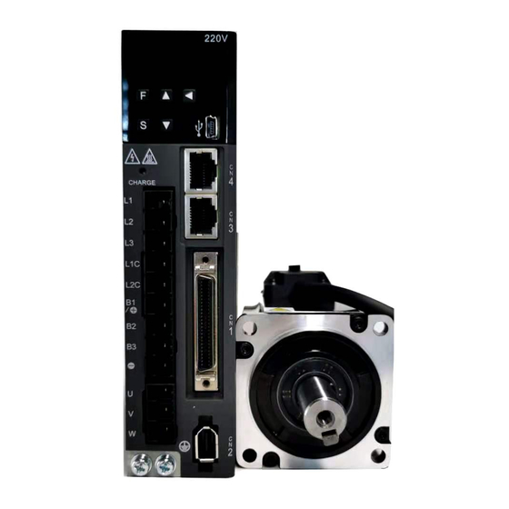
Chapter 1 Basic Information of Servo Drive 1.1 HSD7 Series AC Servo Driver HSD7 series servo drive is mainly used for occasions requiring "high speed, high frequency and high positioning accuracy". The servo drive can maximize the performance of the machine in the shortest possible time and help to improve production efficiency. -
Page 8: Chapter 2 Selection Of Servo Drive
1.3 Model Description 1.3.1 Servo drive model description example ■ Three-phase 220VAC HSD7 HSD7 Series Axis Continuous Output Power Interface Number Current Supply Voltage Type Axis Number Contionous Output Current Power Supply Voltage Interface Type Single 3.0 A 220VAC Analog (standard resolution)/Pulse Axis 6.5 A 8.5 A... -
Page 9: Specification Table
Chapter 2 Selection of Servo Drive 2.1 Ratings and specifications 2.1.1 Rating value ■ Three-phase 220VAC Model 03A□□ 06A□□ 08A□□ 10A□□ 12A□□ 16A□□ 25A□□ Continuous Output Current[Arms] 16.0 25.0 Instantaneous Max. Output Current [Arms] 10.6 14.1 21.2 24.8 29.7 49.5 63.6 AC220V,-15% to +10%, Power Supply... -
Page 10: Overall Dimensions Of Servo Driver
2.1.2 Specification table Item Specifications Control model Position control, JOG operation, Speed contacts, etc. Encoder feedback Serial data encoder: 17-bit or 23-bit (single or multiple turns) Operating ambient temperature/storage Operating ambient temperature: 0~+50℃, storage temperature: -20~+85℃ temperature Conditions of use Ambient humidity/storage Below 90%RH (no freezing or condensation) humidity... - Page 11 2.2 Overall dimensions of servo driver ◆ HSD7-03A 2×M4 单位:毫米 安装孔图 Unit : mm Mounting Hole Diagram ◆ HSD7-06A 58±0.5 3×M4 (安装间距) (mounting pitch) 单位:毫米 安装孔图 Unit : mm Mounting Hole Diagram ◆ HSD7-10A 78±0.5 3×M4 (安装间距) (mounting pitch) 单位:毫米 安装孔图...
-
Page 12: Chapter 3 Installation Of Servo Drive
◆ HSD7-03/06/10A 2×M5 78±0.5 (安装间距) (mounting pitch) 单位:毫米 安装孔图 Unit : mm Mounting Hole Diagram ◆ HSD7-16A/HSD7DS-25A HSD7-15D/HSD7-18D 98±0.5 (安装间距) (mounting pitch) 单位:毫米 安装孔图 Mounting Hole Diagram Unit : mm ◆ HSD7-24D/HSD7-35D 4×M6 (安装间距) (mounting pitch) 单位:毫米 安装孔图 Unit : mm Mounting Hole Diagram... -
Page 13: Chapter 4 Connection Of Servo Unit
Chapter 3 Installation of servo drive 3.1 Precautions for setting For the set environmental conditions, please refer to the following. 2.1.2 Specifications ■ When installed near the heating element To make the temperature around the servo drive conform to the environmental conditions, please control the temperature rise caused by the heat radiation or convection of the heating element. -
Page 14: Anti-Interference Countermeasures
Chapter 4 Connection of Servo Unit 4.1 Wiring and Connecting precautions 段落间距段前: 1 行 设置格式[侯]: 4.1.1 General precautions △ ! Danger Do not change the wiring during power-on. Otherwise, it will lead to electric shock or injury. △ ! Warning ... - Page 15 △ ! Notice Please use the cables designated by our Company as far as possible when connecting. Please confirm the rated current and operating environment of the model when using cables other than those specified by our Company. Use the wiring materials designated by the Company or equivalent products. ...
- Page 16 Please carry out proper grounding treatment. Noise filter Connect the interference filter at an appropriate place to avoid the adverse effect of interference on servo drive. The following is an example of wiring considering anti-interference measures. Servo unit Interference filter Servo motor Above 2.0mm...
- Page 17 Please set the ground wire of interference filter separately from the output wire. In addition, the ground wire should not use the same sleeve as the output wiring of the interference filter and other signal wires, nor should it be tied together. Interference Interference filter...
-
Page 18: Grounding
4.1.3 Grounding Please follow the following for grounding treatment. If proper grounding treatment is adopted, misoperation caused by interference can also be prevented. When connecting the grounding cable, please pay attention to the following points: Please use the grounding above Class D (grounding resistance below 100Ω). ... -
Page 19: Basic Connection Diagram
4.2 Basic connection diagram Three-phase AC 200~230V (50/60Hz) Non-fuse breaker Three-phase AC 380~420V (50/60Hz) Surge protector (Servo Alarm Display) Noise filter Power Power Please connect a surge arrester to the coil of the electromagnetic contactor. Servo motor Magnetic contactor series servo driver Encoder Connect external regenerative resistor... -
Page 20: Wiring Operation Steps Of Main Loop Connector
■ Three phase AC380V power input Terminal Terminal name Specifications symbol Main circuit power supply input terminal L1, L2, L3 Three phase AC 380V~420V,-15%~+10%,50/60Hz for AC power supply input Control power supply L1C, L2C DC 24V,-10% ~ +10% terminal HSD7DS-15D , HSD7DS-18D , Remove the short wire or short piece between B2-B3 when the regeneration capacity is insufficient and connect the external regeneration resistor between B1/⊗... -
Page 21: Power Wiring Diagram
sequence control. Switch on the main circuit power supply after ALM signal OFF (alarm cleared). △ ! Warning Even if the power supply is turned off, high voltage may remain in the servo drive. To prevent electric shock, do not touch the power terminals. -
Page 22: Servo Motor Connection
4.4 Servo motor connection 4.4.1 Terminal symbol and terminal name Servo drive terminals and connectors required for connection between servo drive and servo motor are as follows. Terminal/connector Terminal/connector name symbol Servo motor power supply connection U, V, W terminal Ground terminal Servo motor encoder connector 4.4.2 Pin Arrangement of Connector (CN2) for Encoder... -
Page 23: Wiring Of Servo Drive And Brake
4.4.4 Wiring of Servo Drive and Brake When using a motor with a brake, please select a surge absorber according to the brake current and power supply used. Please confirm the brake action time through the user equipment after connect the surge absorber. Important The brake action time will vary depending on the type of surge absorber. -
Page 24: Connection Of Input And Output Signals
4.5 Connection of input and output signals 4.5.1 Name and function of input/output signal connector (CN1) In factory setting, the pin number, name and function of input and output signals are as follows. Needl Function Needl Function Name Name numb Uniaxial driver Biaxial drive numb... -
Page 25: Examples Of Wiring For Input And Output Signals
4.5.3 Examples of wiring for input and output signals ■ Position control mode * When using the built-in regenerative resistor, terminals B2 and B3 need to be shorted; * When using external regenerative resistor, B2 and B3 terminals need to be disconnected; * Model *24/35D has no built-in regenerative resistor. - Page 26 ■ Speed/Torque Control Mode * When using the built-in regenerative resistor, terminals B2 and B3 need to be shorted; * When using external regenerative resistor, B2 and B3 terminals need to be disconnected; * Model *24/35D has no built-in regenerative resistor. (Reserved) (Reserved) (Reserved)
-
Page 27: Input-Output Loop
4.5.4 Input-output loop Sequential control input loop ◆ Optocoupler Input Loop The CN1-IN0 ~ CN1-IN7 terminals of CN1 port will be described below. Example of relay circuit Example of open collector Circuit Servo unit Servo unit etc. (Note) The external power supply (DC24 V) must have a capacity above 50 mA. The servo-driven input loop uses a bidirectional optocoupler. - Page 28 ◆ Optocoupler output Loop Servo alarm output (ALM) signal, servo ready output (/S-RDY) signal and other sequence control output signals are optocoupler output loops. Connect via relay circuit or line receiver circuit. Example of relay circuit Example of open collector Circuit Servo unit Servo unit Relay...
-
Page 29: Chapter 5 Basic Functions To Be Set Before Operation
Chapter 5 Basic functions to be set before operation 5.1 Operation of Parameters (Pn) The following describes the classification, writing method and setting method of parameters used in this manual 5.1.1 Classification of the parameter The servo drive parameters are divided into the following 2 categories. Category Meaning Setting parameters... -
Page 30: How To Set Parameters
5.1.3 How to Set Parameters Parameters can be set using the panel operator or using iWatch+ debugging software. 5.1.4 Write inhibit setting of parameters This function prohibits the use of panel operators to change parameters. However, iWatch+ debugging software can be used to change parameters. 5.1.5 Initialization of parameter settings Restore the parameters to the function used when factory setting. -
Page 31: Station Address Setting
5.3.2 Station address setting Address of MECHATROLINK-III station Speed Position Torque Setting range Setting Unit Factory setting Effective time Category Pn013 0000〜00FF 0021 Power restart Setup 5.4 Setting of EtherCAT communication specifications The communication specification of EtherCAT communication is set by servo drive parameters PA013 and PA014. -
Page 32: Setting Of Single-Phase Ac Power Input/Three-Phase Ac Power Input
5.5.2 Setting of Single-Phase AC Power Input/Three-Phase AC Power Input Three-phase AC220V power supply input servo drive is of three-phase power supply input specifications, as well as models that can be used under single-phase AC200V power supply input. The servo drive models that can support single-phase AC220V power input are as follows. ... -
Page 33: Functions And Settings Of Over-Travel Prevention
The "forward rotation direction" set by the factory is "counterclockwise rotation (CCW)" as viewed from the load side of the servo motor. Forward/rever Motor rotation direction and encoder frequency division Effective Parameter se command pulse output overtravel (OT) Prohibit Encoder frequency division Torque command pulse output positive... -
Page 34: Select Whether The Over-Travel Prevention Function Is Valid/Invalid
Even in the over-travel state, it is still allowed to drive in the opposite direction by inputting command. 5.8.2 Select whether the over-travel prevention function is valid/invalid The valid/invalid over-travel prevention function can be selected by PN50A = n.X (prohibiting the ... -
Page 35: Overtravel Warning Function
Maximum speed Action speed Maximum speed Actual deceleration time = x Deceleration Time (Pn30A) Action speed Actual deceleration time 5.8.4 Overtravel warning function The over-travel warning function refers to the function of detecting A.9A0 (over-travel warning) when entering the over-travel state during servo ON. When using this function, even if the over-travel signal is input instantaneously, the servo drive can notify the upper device of the occurrence of a warning. -
Page 36: Action Sequence Of Brake
Axis subject to external Vertical axis Servo motor The moving part of a force machine External Brake force Servo motor Prevent power supply from falling due to dead weight when OFF Brake The moving part of a The movable part of the machine is machine prevented from moving due to external force The brake built in the servo motor is a fixed special brake with no excitation action and cannot be used for... - Page 37 n.1 CN1-9,10 Output /BK signal from CN1-OUT1 restart n.2 CN1-11,12 Output /BK signal from CN1-OUT2 [Factory setting] n.3 CN1-32,33 Output /BK signal from CN1-OUT3 n.4 CN1-34,35 Output /BK signal from CN1-OUT4 n.5 CN1-36,37 Output /BK signal from CN1-OUT5 n.6 Don't use /BK signal When multiple signals are distributed to the same output terminal, OR logic is used for signal output.
-
Page 38: Output Time Of Brake Control Output (/Bk) Signal When Servo Motor Stopped
5.9.3 Output Time of Brake Control Output (/BK) Signal when Servo Motor Stopped When the servo motor is stopped, the /BK signal will also be OFF when the servo OFF (SV_OFF) command is input. By setting the servo OFF delay time (Pn506), the time when the SV_OFF command is input to the actual motor is not energized can be changed. -
Page 39: Servo Off And Motor Stop Method In Alarm
Even if the brake command output speed value (Pn507) is set to a value greater than the maximum speed of the servo motor used, it will still be limited to the maximum speed of the servo motor. Important 5.10 Servo OFF and Motor Stop Method in Alarm Servo OFF and motor stop method when alarm occurs are as follows. -
Page 40: Motor Overload Detection Value
The combination and stopping method of parameter setting contents are described in the following table. Parameter Stop method Servo State after the servo Effective Category motor motor stops time Pn00B Pn00A Pn001 n.0 n.0 Dynamic brake [Factory setting] [Factory Zero speed n. -
Page 41: Detection Time Of Overload Alarm (A.720)
Overload warning value Speed Position Torque Setting range Setting Unit Factory setting Effective time Category Pn52B Effective 0〜 100 Setup immediately 5.11.2 Detection time of overload alarm (A.720) When the heat dissipation of the servo motor is poor (the heat sink is small, etc.), the detection value of overload alarm can be reduced to prevent overheating. -
Page 42: Setting Examples Of Electronic Gear Ratio
Encoder resolution Pn20E The amount of movement (command unit) by which the load shaft rotates one circle × Electronic gear ratio Pn210 5.12.2 Setting Examples of Electronic Gear Ratio Examples of settings are as follows. Organizational structure Ball screw Frustum of a cone Belt+pulley Command unit: 0.01°... -
Page 43: Confirmation Before Execution
5.13.2 Confirmation before execution Before setting (initializing) the absolute value encoder, be sure to confirm the following. The write inhibit setting for the parameter must not be set to "writeinhibited" Must be in servo OFF state 5.13.3 Operable tool The tools that can set (initialize) the absolute value encoder and their allocation to the setting (initialization) of the absolute value encoder are as follows. -
Page 44: Chapter 6 Application Function
Chapter 6 Application function 6.1 Distribution of input and output signals The I/O signal connector (CN1) has pre-assigned functions, but some terminals can be assigned other functions or change polarity. Function allocation and polarity setting are performed through parameters. The distribution of input and output signals will be described below. 6.1.1 Distribution of input signals When the distribution of input signals is changed for use ... -
Page 45: Distribution Of Output Signals
6.1.2 Distribution of output signals The output signal can be distributed to the output port of the input/output signal connector (CN1). Allocation is set through Pn50E, Pn50F, Pn510, Pn514. When the distribution of output signals is changed for use No detected signal is in "OFF" state. For example, during speed control, the positioning completion output (/COIN) signal is "OFF". -
Page 46: Ready Output (/S-Rdy) Signal
Rotation detection value Speed Position Torque Setting range Setting Unit Factory setting Effective time Category Pn502 Effective 0~10000 1 min Setup immediately 6.1.6 Ready output (/S-RDY) signal The servo ready output (/S-RDY) signal turns ON in a state where the servo drive can receive a servo ON (SV_ON) command. -
Page 47: Positioning Completion (/Coin) Signal
6.1.8 Positioning Completion (/COIN) Signal When the positioning completion output (/COIN) signal is position control, it indicates the servo motor positioning completion signal. When the difference between the command position from the upper device and the current position of the servo motor (position deviation: value of deviation counter) is less than the set value of the positioning completion amplitude (Pn522), a /COIN signal will be output. -
Page 48: Speed Limit Function During Torque Control
(Note) /NEAR signal needs to be distributed. It can be set to Pn510=n.X (distribution of positioning complete output (/NEAR) signal) and distributed to terminals. Position the setting of NEAR output amplitude. In Pn524 (NEAR Signal Amplitude), the condition for outputting the positioning proximity output (/NEAR) signal (positioning proximity amplitude) is set. -
Page 49: Operation For Momentary Power Interruptions
In addition, through Pn408 = n X (speed limit selection), the upper speed limit value used for the speed limit value can be selected from "motor maximum speed" and "overspeed alarm detection speed". When limited by a speed equal to the maximum speed of the motor, select "Overspeed Alarm Detection Speed". Effective Parameter Meaning... - Page 50 Execution sequence This function can be executed by a command issued by an upper device or a servo drive unit. Whether it is executed by the upper device or servo drive unit is selected by Pn008=n.X (function selection under voltage). ◆...
-
Page 51: Setting Of Maximum Speed Of Motor
Parameters related to SEMI F47 specification support functions are as follows. Torque limitation when main loop voltage drops Speed Position Torque Setting range Setting Unit Factory setting Effective time Category Pn424 Effective 10~100 1% * Setup immediately Torque limit release time when main loop voltage drops. Speed Position Torque... -
Page 52: Setting Of Encoder Frequency Division Pulse Output
Upper device Servo unit Serial data Frequency Serial Data division loop Pulse Conversion Output phase morphology When rotating forward (forward When reversing (negative direction) direction) (phase b 90 leading) (phase a 90 leading) A Phase A Phase B Phase B Phase C Phase C Phase (Note) The pulse amplitude of the origin within the encoder 1 coil varies depending on the number of encoder divided pulses (Pn212) - Page 53 Setting value: 16 PAO signal PBO signal 1 circle...
-
Page 54: Soft Limit Function
6.6 Soft limit function The so-called soft limit refers to the function of forcibly stopping when the movable part of the machine exceeds the soft limit when no overtravel signal (P-OT, N-OT) is used. When using soft time limit, the following settings are required. Set the soft limit function to active Set soft limit 6.6.1 The valid/invalid choice of soft limit function... -
Page 55: Internal Torque Limit
6.7.1 Internal torque limit The internal torque limit limits the maximum output torque at a constant time by the torque limit values set by the forward torque limit (Pn402) and the reverse torque limit (Pn403). Forward rotation torque limit Speed Position Torque Setting range... -
Page 56: Torque Limit Detection Output (/Clt) Signal
Output torque variation at external torque limit Indicates the output torque when the internal torque limit is set to 800%. The rotation direction of the motor is set to Pn000 = n.0 (with CCW direction as forward rotation) as an example. -
Page 57: Forced Stop Function
Parameter setting when using multiple coil absolute value encoder Effective Parameter Meaning Category time n.0 Used as multiple coils absolute value encoder. [Factory setting] A battery is needed. Used as incremental encoder. Power Pn002 n.1 Setup No battery is required restart Used as 1 coil absolute value encoder. -
Page 58: Methods Of Recovery From Compulsory Stop
* Percentage relative to rated torque of motor. When the servo motor is stopped by setting the deceleration time (Pn30A) during servo OFF and forced stop When setting the deceleration time of the servo motor to stop the servo motor, Pn30A (deceleration time at servo OFF and forced stop) is set. -
Page 59: Chapter 7 Trial Operation
Chapter 7 Trial operation Introduce the process and operation steps of the trial run and the functions that are convenient to use during the trial run. 7.1 Commissioning process 7.1.1 Process of servo motor test run The steps of the trial run are as follows. Steps Content Settings and installation... -
Page 60: Operable Tool
The main circuit power supply must be ON. No alarm has occurred. Hardware Base Blocking (HWBB) function must be invalid. Must in servo OFF state. The setting of JOG speed must take into account the operating range of the machine used. Set the JOG speed through the following parameters. -
Page 61: Chapter 8 Panel Display And Use Of Panel Operators
Chapter 8 Panel Display and Use of Panel Operators 8.1 Panel operator 8.1.1 Name and function of panel operator keys The panel operator consists of a panel display part and panel operator keys. The panel operator can display the status, perform auxiliary functions, set parameters and monitor the action of servo drive. -
Page 62: Status Display Mode
8.1.3 Status display mode The status is shown below. Position Data Abbreviation symbol Off: The current display is Axis A. Illumination: the current display is axis b ■ Display Contents of Bit Data Display Meaning Control power supply ON Display When the servo control power supply is on, it lights up. -
Page 63: Operation Of Parameters (Pa) In Panel Operator
Abbreviation symbol Meaning of the contents Prohibit forward-turning side drive state Indicates that the inhibit forward drive input (P-OT) signal is in an open circuit state. It is forbidden to reverse the side drive state. Indicates that the inhibit reverse side drive input (N-OT) signal is in an open circuit state. -
Page 64: Setting Method Of "Function Selection Type
8.2.2 Setting Method of "Function Selection Type" The function selection type sets various functions by selecting from the functions assigned to each digit of the display number of the panel operator. The following describes the setting method of the function selection type, taking the control mode selection (Pn000.1) of the function selection basic switch (PA000) from speed control to position control as an example. -
Page 65: Basic Operation Of Monitoring Display
8.3.1 Basic operation of monitoring display The following description will take Un000 (motor rotation speed) as an example. Operation Steps Display after operation Operation Press the F key to select the auxiliary function. If the parameter number does not show UA000, press the UP or DOWN key to show "UA000". -
Page 66: Operation Of Auxiliary Function (Fa) In Panel Operator
8.4 Operation of Auxiliary Function (FA) in Panel Operator The auxiliary function is used to perform functions related to setting and adjusting the servo drive. Displays the number beginning with FA the panel operator. Display Example (JOG Run) The following describes the operation steps when using the panel operator. Please refer to the contents of each function for confirmation items and relevant parameters before execution. -
Page 67: Origin Search (Fa003)
Operation Steps Display after operation Operation Press F key to enter servo ON state. Press the UP key (forward rotation) or the DOWN key (reverse rotation), during which the servo motor rotates at the speed set by Pn304 or Pn383. Press MODE/SET key to enter servo OFF state. -
Page 68: Initialization Of Parameter Settings (Fa005)
8.4.5 Initialization of parameter settings (FA005) Please refer to the following contents besides the operation steps Operation Steps Display after operation Operation Press the F key to select the auxiliary function. UP or DOWN key display "FA005". Press S key, and the display content is shown in the left figure. -
Page 69: Automatic Adjustment Of Analog (Speed And Torque) Command Bias (Fa009)
8.4.8 Automatic Adjustment of Analog (Speed and Torque) Command Bias (FA009) Please refer to the following contents besides the operation steps Operation Steps Display after operation Operation Press the F key to select the auxiliary function. UP or DOWN key display "FA009". Press S key, and the display content is as shown in the left figure, and "rEF_o”... -
Page 70: Automatic Adjustment Of Offset Of Motor Current Detection Signal(Fa00E
Operation Steps Display after operation Operation Press the S key to display the current offset. Press the UP or DOWN key to adjust and stop the servo motor. This value is the offset. "donE" will flash and then switch to the display on the left when the f key is pressed. -
Page 71: Display Software Version (Fa012)
Operation Steps Display after operation Operation UP or DOWN key display "FA011". Press the S key to display the current motor code. The display content will be shown in the left figure. Press F key to display the current servo internal parameter 1. Press F key to display the current servo internal parameter 2. -
Page 72: Easyfft(Fn206
Operation Steps Display after operation Operation Press the UP or DOWN key to set the adjustment mode. TUNING MODE(Adjust the strength of the setting) 0: Pay attention to the adjustment of stability. 1. Pay attention to responsive adjustment. (Note) TYPE (Rigid type) is fixed as "2". In the non-servo ON state, a servo ON (/S-ON) signal is input from the upper device. -
Page 73: Load Inertia/Mass Detection (Fa208)
Operation Steps Display after operation Operation After the detection process is normally completed, the "E_FFt" display stops blinking and shows the detected resonance frequency. If the check-out fails, "F----" is displayed. When setting the check-out result, you must proceed to step 9. If only the resonance frequency is confirmed without setting the detection result, press the S key to return to step 2. -
Page 74: Chapter 9 Maintenance
Chapter 9 Maintenance 9.1 Inspection and component replacement The inspection of servo drive and component replacement will be described below. 9.1.1 Inspection Servo drive does not need routine inspection, but the following items need to be inspected at least once a year. -
Page 75: Alarm Display
◆ When using encoder cable with battery unit 1. Only connect to the servo drive control power supply. If the battery is removed after the servo drive control power supply is OFF (including when the encoder cable is removed), the memory data in the absolute value encoder will be lost. Important 2. - Page 76 Alarm list Alarm Alarm Alarm Alarm name Alarm content stop reset number mode Whether A.020 Parameter and check exceptions The data of internal parameters of servo drive is abnormal. Gr.1 A.021 Parameter format exception The data format of internal parameters of servo drive is abnormal. Gr.1 A.022 System and check exceptions...
-
Page 77: Cause Of Alarm And Treatment Measures
deviation caused by speed limit when executed by the speed limit value (Pn529 or Pn584) when the servo is ON. When a servo is on position command is input in this state, the limit is not released and the set value of the warning value (Pn520) for excessive position deviation is exceeded. - Page 78 Alarm number: Reason Confirmation method The treatment measures Alarm name A.0b0: After performing the auxiliary function of Connect to the servo drive power supply Servo ON command is energizing the motor, servo is sent from again. Or perform a software reset. invalid alarm the upper device ON(SV_ON) command The main loop cable is incorrectly wired...
- Page 79 Alarm number: Reason Confirmation method The treatment measures Alarm name Power supply voltage exceeds Adjust the AC/DC power supply voltage to the Measure the supply voltage. specification range product specifications. Improve the power supply condition and The power supply is in an unstable state switch on the servo drive power again after Measure the supply voltage.
- Page 80 Alarm number: Reason Confirmation method The treatment measures Alarm name Connect to the servo drive power supply A.840: Encoder malfunction again. When an alarm still occurs, replace the Encoder data alarm servo motor or encoder. (Detected on encoder Correct wiring encoder periphery Incorrect operation of encoder due to...
- Page 81 Alarm number: Reason Confirmation method The treatment measures Alarm name Reconnect the power to the servo unit. It may A.C80: be a servo motor or a linear encoder fault Encoder clearance Encoder failure when an alarm still occurs. Replace the servo exception motor or linear encoder.
- Page 82 Alarm number: Reason Confirmation method The treatment measures Alarm name A.d30 Location data is too Location data exceeds ±1879048192 Confirm the input command pulse counter. Revise operating specifications. large transmission period reason transmission cycle A.E02: MECHATROLINK has changed variation of the upper device is eliminated. MECHATROLINK Connect to the servo drive power supply Internal synchronization...
-
Page 83: Alarm Reset
9.2.3 Alarm reset When the servo alarm output (ALM) signal occurs, reset it by any of the following methods after eliminating the alarm cause. Before resetting the servo alarm, be sure to eliminate the alarm reason. If the alarm reset is executed without excluding the alarm reason, equipment damage or fire may occur when the alarm reset is kept running. - Page 84 Alarm Alarm name Alarm content Reset number (Latch Exception) Command Warning 1 (Out of Automatic A.95A When the command condition is not sufficient, the command is executed. Command Conditions) reset * Command Warning Automatic A.95B An unsupported command was instructed. (Command Not Supported) reset * Command...
-
Page 85: Reasons For Warning And Countermeasures
9.3.2 Reasons for Warning and Countermeasures The following table lists the cause of the alarm and the treatment measures. If the fault cannot be cleared after processing according to the following table, please contact our company. Alarm number: Reason Confirmation method The treatment measures Alarm name Confirm the connection of... -
Page 86: Monitoring Of Communication Data When Alarms And Warnings Occur
9.4 Monitoring of communication data when alarms and warnings occur The command data when an alarm or warning (e.g. data setting warning (A.94) or command warning (A.95)) occurs can be monitored through the following parameters. The following is the data when an alarm or warning occurs under normal conditions. - Page 87 Fault contents Reason Confirmation method The treatment measures connector connection The action of servo Poor cable connection of servo power line (U, V, W phase) and Looseness fastening terminals motor is not stable motor encoder or serial conversion unit connectors and correct wiring. may be unstable.
- Page 88 Fault contents Reason Confirmation method The treatment measures Improper matching of servo Confirm whether gain adjustment Perform automatic adjustment (no upper gain has been implemented. command). Confirm the setting value of speed The speed loop gain (Pn100) is Set the correct speed loop gain (Pn100) loop gain (PN100).
- Page 89 Fault contents Reason Confirmation method The treatment measures torque control (Pn001 = n.X, than free running stop. or Pn001 = n.X). The position of the limit switch Set the limit switch at the appropriate and the length of the toggle position.
-
Page 90: Chapter 10 List Of Parameter
Chapter 10 List of parameter 10.1 List of servo parameters 10.1.1 Method for distinguishing the list When the factory setting values of Axis A Indicates when the parameter changes and the change Indicates number and Axis b of the biaxial driver are takes effect. -
Page 91: List Of Servo Parameters
10.1.2 List of servo parameters The parameter list is as follows. (Note) The following parameters are factory settings and should not be changed. • Appointment Parameters • Parameters not recorded in this manual Setting Available Categor Rema Pn No. Size Name Setting range Factory setting... - Page 92 Setting Available Categor Pn No. Size Name Setting range Factory setting Model Unit time 0000 Function selection Power 0000~4213 Setup application switch 2 restart 0011 n.X Speed/position control selection (T-REF assignment) Model No T-REF allocation. Use T-REF as the external torque limit input. (Torque Limit Enabled in Bus Mode) (B)...
- Page 93 Setting Factory Available Categor Rema Pn No. Size Name Setting range Unit setting time Function selection Power 0000~0044 0001 Setup application switch A restart n.X Stop Method in Case of Gr.2 Alarm Remarks DB stop or free running stop (stop method is the same as Pn001 = n.X).
- Page 94 Factory Available Categor Pn No. Size Name Setting range Setting Unit Model setting time Modbus/CANopen Power Communication parameter 0100 Setup restart selection switch n.X Modbus communication baud rate selection Remarks 9600 bps 19200 bps 38400 bps 57600 bps 115200 bps n.X...
- Page 95 Setting Available Catego Rema Pn No. Size Name Setting range Factory setting Unit time Effective Adjust Pn100 Velocity loop gain 10~20000 0.1 Hz immediately ment Velocity loop integration Effective Adjust Pn101 15~51200 0.01 ms 2000 time parameter immediately ment Effective Adjust Pn102 Position loop gain...
- Page 96 Factory Available Catego Rema Pn No. Size Name Setting range Setting Unit setting time Automatic Gain Switching Effective Adjust 0000~0052 0000 Class Switch 1 immediately ment Gain switching selector switch n.X Manual gain switching The gain is manually switched by the G_SEL of the servo command output signal (SVCMD_IO).
- Page 97 Factory Available Categor Rema Pn No. Size Name Setting range Setting Unit setting time Power Adjustm Control switch 0000~0021 0021 restart n. X Rotation direction selection Remarks Select Model tracking control 1 mould. Select Model tracking control 2 mould. Pn14F n.
- Page 98 Factory Available Categor Pn No. Size Name Setting range Setting Unit Model setting time Position control command Power 0000~2236 0000 Setup form selector switch restart n.X Command pulse pattern Sign+Pulse, Positive Logic CW+CCW Pulse Sequence, Positive Logic 90° phase difference two-phase pulse (phase A+phase B) 1 times, positive logic 90°...
- Page 99 Factory Available Catego Rema Pn No. Size Name Setting range Setting Unit setting time Effective Pn302 Internal set speed 2 0~10000 1 min Setup immediately Effective Pn303 Internal set speed 3 0~10000 1 min Setup immediately Effective Pn304 Jog (JOG) speed 0~10000 1 min Setup...
- Page 100 Factory Available Catego Rema Pn No. Size Name Setting range Setting Unit setting time Frequency of 1st notch Effective Adjust Pn409 50~5000 1 Hz 5000 filter immediately ment Q value of the 1st notch Effective Adjust Pn40A 50~1000 0.01 filter immediately ment Effective...
- Page 101 Factory Available Catego Pn No. Size Name Setting range Setting Unit Model setting time When main loop voltage Effective Pn425 drops 0~1000 1 ms Setup immediately Torque limit release time Torque feedforward moving Effective Pn426 0~5100 0.1 ms Setup average time immediately Velocity fluctuation...
- Page 102 Factory Available Categ Pn No. Size Name Setting range Setting Unit Model setting time 1801 (axis A) 5841 (axis b) Power Input signal selection 1 0000~9991 Setup restart 0801 (axis A) 0841 (axis b) n.X Allocation mode of input signals Remarks Appointment Parameters (Do Not Set) According to different signals.
- Page 103 Setting Factory setting Available Categor Rema Pn No. Size Name Setting range Unit time Power Input signal selection 3 0000~9999 8888 Setup restart n.X Distribution of motor rotation direction switching input (/SPD-D) signal Remarks CN1-IN0 takes effect when the input signal is ON. CN1-IN1 takes effect when the input signal is ON.
- Page 104 Setting Available Categor Pn No. Size Name Setting range Factory setting Unit time arks 6611 (axis A) Power Output signal selection 2 0000~6666 Setup 6644 (axis b) restart n.X Distribution of torque limit detection output (/CLT) signal Remarks The above signals are output from CN1-OUT0 (7, 8) output terminals. The above signals are output from CN1-OUT1 (9, 10) output terminals.
- Page 105 Setting Factory Available Categor Pn No. Size Name Setting range Model Unit setting time 8888 Power Input signal selection 4 0000~9999 Setup 8836 (axis A) restart 8872 (axis b) n.X Distribution of input (/DEC) signal of origin reset deceleration switch CN1-IN0 takes effect when the input signal is ON.
- Page 106 Factory Available Categor Rema Pn No. Size Name Setting range Setting Unit setting time Power Output signal selection 5 0000~9999 0000 Setup restart n.X Appointment parameters (do not change it) n.X Distribution of command pulse input multiplication switching input (/PSEL) Signal CN1-IN0 takes effect when the input signal is ON.
- Page 107 Factory Available Categor Pn No. Size Name Setting range Setting Unit Model setting time Input signal inversion Power 0000~1111 0000 Setup setting 2 restart n.X CN1-IN4 terminal input signal inversion Not reverse signal. Reverses the signal. n.X CN1-IN5 terminal input signal inversion Not reverse signal.
- Page 108 Factory Available Categ Remar Pn No. Size Name Setting range Setting Unit setting time Track the specified alert Effective Pn548 0000〜FFFF 0000 Setup number immediately Residual vibration Effective Pn560 1~3000 0.1% Setup detection amplitude immediately Effective Pn561 Overshoot detection value 0~100 Setup immediately...
- Page 109 Factory Available Categ Rema Pn No. Size Name Setting range Setting Unit setting time 10000 Effective Pn80A Section linear 1~65535 Command immediately Setup acceleration parameters unit/s 10000 Effective Pn80B Section linear 1~65535 Command immediately Setup acceleration parameters unit/s 10000 Effective Pn80C Accelerating parameter...
- Page 110 Factory Available Categor Remar Pn No. Size Name Setting range Setting Unit setting time Power Allocation command data 0000~1111 0010 Setup restart n.X OPTION area function allocation Invalidates OPTION area function assignment. Make OPTION area function allocation valid. Pn81F n.X Location control command TFF/TLIM function allocation Make allocation invalid.
- Page 111 Factory Available Categ Remar Pn No. Size Name Setting range Setting Unit setting time Option monitoring Effective 0000〜FFFF 0000 Setup selection immediately Monitoring function Pn825 Setting value 0000H~ Same as option monitoring 1. 0084H 10000 Effective Stop using linear Pn827 1~65535 Command immediatel...
- Page 112 Factory Available Categor Rema Pn No. Size Name Setting range Setting Unit setting time OPTION area function Power 0000~1F1F 1F1E Setup allocation 3 restart n.X Allocation of P_CL(OPTION) 0~F The allocation is the same as V_PPI. n.X Valid/invalid selection of P_CL allocation Make P_CL bit allocation invalid.
- Page 113 Factory Available Categor Rema Pn No. Size Name Setting range Setting Unit setting time Power Motion setting 0000~0001 0000 Setup restart Selection of linear acceleration and deceleration parameters n.X Pn80A~Pn80F, Pn827 are used. (the settings of Pn834 ~ Pn840 are invalid) Pn834~...
- Page 114 Factory Available Categ Remar Pn No. Size Name Setting range Setting Unit setting time SVCMD_IO (input signal Effective monitoring) 0000~1717 0000 Setup immediately Distribution function 1 Allocation of input signal monitoring for CN1-IN0 (SVCMD_IO) n.X Set CN1-13 input signal monitoring to bit 24 (IO_STS1). Set CN1-13 input signal monitoring to bit 25 (IO_STS2).
- Page 115 Factory Available Catego Pn No. Size Name Setting range Setting Unit setting time arks SVCMD_IO (output signal Effective monitoring) 0000~1717 0000 Setup immediately Distribution function 1 Distribution of output signal monitoring for CN1-OUT1 (SVCMD-IO) n.X Set CN1-OUT1 output terminal monitoring to D24 (IO1_ STS1). Set CN1-OUT1 output terminal monitoring to D25 (IO1_ STS1).
-
Page 116: Chapter 11 Operation Of Debugging Software (Iwatch+)
Chapter 11 Operation of Debugging Software (iWatch+) The following functions can be realized online by using the upper computer software (iWatch+): • Parameter management: parameter setting and adjustment • State monitoring: monitoring the working state and relevant data of the servo system •... - Page 117 The following describes the adjustment of automatic adjustment (no upper command). • The automatic adjustment (without a bit command) is based on the set speed loop gain (Pn100). If vibration occurs at the beginning of the adjustment, the correct adjustment cannot be made. Please reduce the speed loop gain (Pn100) until it stops vibrating and adjust.
- Page 118 • Select the load movement inertia mark 0: No estimation of moving inertia [factory setting] 1. Estimated moment of inertia Selection pattern Selection Description pattern Make standard gain adjustments. In addition to 1: Standard gain adjustment, notch filter and Type A vibration suppression are automatically adjusted.
-
Page 119: Motor Code Is Written To Encoder Eerom Operation(Fa301
Motor code is written to encoder EEROM operation(FA301) Step Display Operation Press the left button and UP button to display "FA010". Press the S key, the display content is shown on the left. Press the left button and UP button to enter the advanced authority P.0010. -
Page 120: Motor Zero Position Check And Reset Operation (Fa300
Motor zero position check and reset operation (FA300) Step Display Operation Perform this operation, the motor must without load! ! ! Press F to select auxiliary function. Press the UP or DOWN key to display "FA011". Press the S key, the display content is as shown on the left, "0.6910"... - Page 121 Version: V0.1 Thanks for choosing HNC product. Any technique support, please feel free to contact our support team Tel: 86(20)84898493 Fax: 86(20)61082610 URL: www.hncelectric.com Email:support@hncelectric.com...
Need help?
Do you have a question about the HSD7-E Series and is the answer not in the manual?
Questions and answers