AUMA SAR Series Manuals
Manuals and User Guides for AUMA SAR Series. We have 5 AUMA SAR Series manuals available for free PDF download: Operating Instructions Manual, Operation Instructions Manual, Manual
AUMA SAR Series Operating Instructions Manual (104 pages)
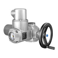
Multi-turn actuators
Brand: AUMA
|
Category: Controller
|
Size: 2 MB
Table of Contents
Advertisement

AUMA SAR Series Operation Instructions Manual (100 pages)
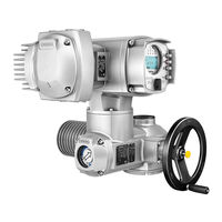
Multi-turn actuators
Brand: AUMA
|
Category: Controller
|
Size: 2 MB
Table of Contents
AUMA SAR Series Operation Instructions Manual (64 pages)
Multi-turn actuators with local controls AUMA SEMIPACT SEM 01.1/SEM 02.1
Brand: AUMA
|
Category: Controller
|
Size: 1 MB
Table of Contents
Advertisement

AUMA SAR Series Operation Instructions Manual (48 pages)
Multi-turn actuators, AUMA NORM (without controls)
Brand: AUMA
|
Category: Controller
|
Size: 1 MB
Table of Contents

AUMA SAR Series Manual (52 pages)
Multi-turn actuators with actuator controls AC 01.2-SIL/ACExC 01.2-SIL
Brand: AUMA
|
Category: Controller
|
Size: 1 MB
Table of Contents
Advertisement