ABB ProcessMaster FEP630 Manual
Electromagnetic flowmeter
Hide thumbs
Also See for ProcessMaster FEP630:
- Operating instruction (60 pages) ,
- Operating instruction (152 pages) ,
- Manual (32 pages)
Table of Contents
Advertisement
—
A B B M E A S U R E M E N T & A N A L Y T I C S | C O M M I S S I O N I N G I N S T R U C T I O N
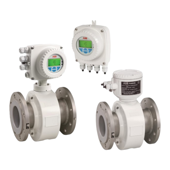
ProcessMaster FEP630, HygienicMaster FEH630
Electromagnetic flowmeter
—
Introduction
FEP630
FEH630
Intelligent design and extended functions for
FET630
efficient system operation at reduced costs and with
higher profitability.
ProcessMaster FEP630
The first choice for demanding applications in the
processing industry.
HygienicMaster FEH630
The first choice for demanding applications in the
food industry.
Devices-Firmware version: 01.07.00
Measurement made easy
Additional Information
Additional documentation on FEP630, FEH630 is
available for download free of charge at
www.abb.com/flow.
Alternatively simply scan this code:
Advertisement
Table of Contents


Need help?
Do you have a question about the ProcessMaster FEP630 and is the answer not in the manual?
Questions and answers