
Related Manuals for ABB ProcessMaster


Summary of Contents for ABB ProcessMaster
- Page 1 CI/FEX300/FEX500-EN ProcessMaster, HygienicMaster FEX300, FEX500 Commissioning Instruction Electromagnetic Flowmeter...
- Page 3 Fax: +49 621 381 931-29031 automation.service@de.abb.com © Copyright 2012 by ABB Automation Products GmbH Subject to changes without notice This document is protected by copyright. It assists the user in safe and efficient operation of the device. The contents of this document, whether whole or in part, may not be copied or reproduced without prior approval by the copyright holder.
-
Page 4: Table Of Contents
Supports for meter sizes larger than DN 400..................14 4.1.2 Mounting the measuring tube........................15 Torque information ............................16 4.2.1 ProcessMaster in flange design and HygienicMaster in flange or wafer-type design ......16 4.2.2 Variable process connections HygienicMaster ..................20 Information on EHEDG conformity.......................21 Information on 3A conformity ........................21 Installation Requirements..........................22... - Page 5 5.4.4 Connecting the signal and magnet coil cables..................35 Connecting the flowmeter sensor.........................36 5.5.1 Metal terminal box in the case of ProcessMaster and HygienicMaster ..........36 5.5.2 Plastic terminal box in the case of ProcessMaster ................37 5.5.3 Connection via cable conduit ........................38 5.5.4...
- Page 6 Contents 8.3.2 Limit values for the electrode deposits....................72 8.3.3 Limit values for the electrode impedance .....................72 8.3.4 Recommended settings for the Trend Logger ..................72 Appendix ................................73 Other applicable documents ........................73 Approvals and certifications .........................73 4 - EN FEX300, FEX500 CI/FEX300/FEX500-EN...
-
Page 7: Safety
Safety Safety General information and notes for the reader You must read these instructions carefully prior to installing and commissioning the device. These instructions are an important part of the product and must be kept for future reference. These instructions are intended as an overview and do not contain detailed information on all designs for this product or every possible aspect of installation, operation and maintenance. -
Page 8: Intended Use
Prior to using corrosive and abrasive materials for measurement purposes, the operator must check the level of resistance of all parts coming into contact with the materials to be measured. ABB Automation Products GmbH will gladly support you in selecting the materials, but cannot accept any liability in doing so. -
Page 9: Plates And Symbols
Safety Plates and symbols 1.5.1 Safety- / warning symbols, note symbols DANGER – <Serious damage to health / risk to life> This symbol in conjunction with the signal word "Danger" indicates an imminent danger. Failure to observe this safety information will result in death or severe injury. DANGER –... -
Page 10: Transport Safety Information
The power supply and the electrical circuit for the coils of the flowmeter sensor are dangerous and pose a contact risk. The coil and signal circuit may be connected with the corresponding ABB flowmeter sensors only. Use the supplied cable. -
Page 11: Safety Instructions For Operation
Safety Safety instructions for operation During operation with hot fluids, contact with the surface may result in burns. Aggressive fluids may result in corrosion or abrasion of the parts that come into contact with the medium. As a result, pressurized fluids may escape prematurely. Wear to the flange gasket or process connection gaskets (e.g., aseptic threaded pipe connections, Tri-Clamp, etc.) may enable a pressurized medium to escape. -
Page 12: 1.12 Returning Devices
If it is not possible to dispose of old equipment properly, ABB Service can accept and dispose of returns for a fee. 1.13.2 RoHS Directive 2002/95/EC With the Electrical and Electronic Equipment Act (ElektroG) in Germany, the European Directives 2002/96/EC (WEEE) and 2002/95/EC (RoHS) are translated into national law. -
Page 13: Device Designs
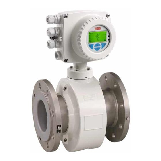
The transmitter and the flowmeter sensor form a single mechanical entity. The transmitter is available in two housing designs: Single-compartment housing: With the single-compartment housing, the electronics area and the connection area are not separated from each other. ProcessMaster HygienicMaster G01316 Fig. 1: Transmitter with single-compartment housing Dual-compartment housing: With the dual-compartment housing, the electronics area and the connection area are separated from each other. -
Page 14: Model With Remount Mount Design
Without a pre-amplifier, the maximum permissible signal cable length is 50 m (164 ft) with a minimum conductivity of 5 µS/cm. With a pre-amplifier, the maximum permissible signal cable length is 200 m (656 ft). Two terminal box variants are available for the ProcessMaster flowmeter sensor: • Aluminum terminal box •... -
Page 15: Transport
Transport Transport Inspection Check the devices for possible damage that may have occurred during transport. Damages in transit must be recorded on the transport documents. All claims for damages must be claimed without delay against the shipper and before the installation. Transport of flanged units smaller than DN 450 Warning –... -
Page 16: Mounting
Mounting Mounting Important (Note) An additional document with Ex safety instructions is available for measuring systems that are used in explosion hazardous areas. As a result, it is crucial that the specifications and data it lists are also observed. General information on installation The following points must be observed for the installation: •... -
Page 17: Mounting The Measuring Tube
Mounting 4.1.2 Mounting the measuring tube The device can be installed at any location in a pipeline under consideration of the installation conditions. Notice - Potential damage to device! Use of graphite with the flange or process connection gaskets is prohibited. In some instances, an electrically conductive coating may form on the inside of the measuring tube. -
Page 18: Torque Information
Mounting Torque information 4.2.1 ProcessMaster in flange design and HygienicMaster in flange or wafer-type design Meter size DN Nominal Max. tightening torque [Nm] pressure Inch Hard/soft rubber lining PTFE, PFA, ETFE lining Steel flange Stainless steel Steel flange Stainless steel... - Page 19 Mounting Meter size DN Nominal Max. tightening torque [Nm] pressure Inch Hard/soft rubber lining PTFE, PFA, ETFE lining Steel flange Stainless steel Steel flange Stainless steel flange flange PN40 41.26 27.24 71.45 71.45 PN63 71.62 60.09 109.9 112.6 CL150 22.33 22.33 66.22 66.22...
- Page 20 Mounting Meter size DN Nominal Max. tightening torque [Nm] pressure Inch Hard/soft rubber lining PTFE, PFA, ETFE lining Steel flange Stainless steel Steel flange Stainless steel flange flange PN10 23.54 27.31 86.06 89.17 PN16 88.48 61.71 99.42 103.1 PN25 137.4 117.6 166.5 133.9...
- Page 21 Mounting Meter size DN Nominal Max. tightening torque [Nm] pressure Inch Hard/soft rubber lining ETFE lining Steel flange Stainless steel Steel flange Stainless steel flange flange PN10 391.7 304.2 On request On request PN16 646.4 511.8 On request On request 32“...
-
Page 22: Variable Process Connections Hygienicmaster
Mounting 4.2.2 Variable process connections HygienicMaster Meter size DN Max. tightening torque inch 1 ... 2 1/25 ... 3/32“ PVC/POM: 0.2 Brass/1.4571: 3 3 ... 10 3/8“ 1/2“ 3/4“ 1 1/4“ 1 1/2“ 2 1/2“ 20 - EN FEX300, FEX500 CI/FEX300/FEX500-EN... -
Page 23: Information On Ehedg Conformity
(EHEDG Position Paper: "Hygienic Process connections to use with hygienic components and equipment"). All weld stub combinations provided by ABB are approved. The threaded pipe connection conforming to DIN11851 is approved when used in conjunction with an EHEDG-approved process gasket (e.g. Siersema brand). -
Page 24: Installation Requirements
Mounting Change from one to two columns Installation Requirements 4.5.4 Vertical connections • Vertical installation for measuring abrasive fluids, preferably with 4.5.1 Flow direction flow in upward direction. The device measures the flowrate in both directions. Forward flow is the factory setting, as shown in Fig. 10. G00039-01 G00657-01 Fig. -
Page 25: Installation In The Vicinity Of Pumps
Mounting 4.5.8 Installation in the vicinity of pumps 4.5.11 Installation in pipelines with larger nominal diameters • For flowmeter primaries which are to be installed in the vicinity of pumps or other vibration generating equipment, the utilization of Determine the resulting pressure loss when using reduction pieces mechanical snubbers is advantageous. -
Page 26: Ground
G00662-01 Flange design Wafer type design Fig. 21: Metal pipe, without lining (example) "A" Grounding in the case of a plastic terminal box (ProcessMaster only) Important (Note) • Grounding is illustrated using the example of the dual-compartment transmitter housing; in the case of transmitters with single-compartment housing, grounding is to be performed as shown. -
Page 27: Metal Pipe With Loose Flanges
G00663-01 Flange design Wafer type design Fig. 22: Metal pipe, without lining (example) "A" Grounding in the case of a plastic terminal box (ProcessMaster only) Important (Note) • Grounding is illustrated using the example of the dual-compartment transmitter housing; in the case of transmitters with single-compartment housing, grounding is to be performed as shown. -
Page 28: Plastic Pipes, Non-Metallic Pipes Or Pipes With Insulating Liner
Flange design Wafer type design Fig. 23: Plastic pipes, non-metallic pipes or pipes with insulating lining "A" Grounding in the case of a plastic terminal box (ProcessMaster only) Important (Note) • Grounding is illustrated using the example of the dual-compartment transmitter housing; in the case of transmitters with single-compartment housing, grounding is to be performed as shown. -
Page 29: Sensor Type Hygienicmaster
Mounting 4.6.5 Sensor type HygienicMaster Ground the stainless steel model as shown in the figure. The measuring fluid is grounded via the adapter (1) and an additional ground is not required. Fig. 24 4.6.6 Ground for devices with protective plates The protective plates are used to protect the edges of the liner in the measuring tube, e.g., for abrasive fluids. -
Page 30: Electrical Connections
Electrical connections Electrical connections Routing the signal and magnet coil cable Observe the following points when routing cables: • A magnet coil cable (red and brown) is run parallel to the signal lines (violet and blue). As a result, only one cable is required between the flowmeter sensor and the transmitter. Do not run the cable over junction boxes or terminal strips. -
Page 31: Preparing The Signal And Magnet Coil Cable In The Case Of Transmitters With Dual-Compartment Housing
Electrical connections Preparing the signal and magnet coil cable in the case of transmitters with dual-compartment housing 5.2.1 Cable with part number D173D027U01 Prepare both cable ends as shown. Important (Note) Use wire end sleeves. • Wire end sleeves 0.75 mm (AWG 19), for shielding (1S, 2S) •... -
Page 32: Cable With Part Number D173D031U01
Electrical connections 5.2.2 Cable with part number D173D031U01 Prepare both cable ends as shown. Important (Note) Use wire end sleeves. • Wire end sleeves 0.75 mm (AWG 19), for shielding (1S, 2S) • Wire end sleeves 0.5 mm (AWG 20), for all other wires The shields may not touch (signal short circuit). -
Page 33: Preparing The Signal And Magnet Coil Cable In The Case Of Transmitters With Single-Compartment Housing.31
Electrical connections Preparing the signal and magnet coil cable in the case of transmitters with single-compartment housing M1 M2 D1 D2 SE 3 2S E2 E1 1S D173D027U01 M1 M2 D1 D2 SE 3 2S E2 E1 1S D173D031U01 G01323 Fig. -
Page 34: Cable With Part Number D173D027U01
Electrical connections Important (Note) • Use wire end sleeves. Wire end sleeves 0.75 mm (AWG 19), for shielding (1S, 2S) Wire end sleeves 0.5 mm (AWG 20), for all other wires • The shields may not touch (signal short circuit). Prepare the cable end on the transmitter side as shown in Fig. -
Page 35: Connecting The Transmitter
Electrical connections Connecting the transmitter Important (Note) An additional document with Ex safety instructions is available for measuring systems that are used in explosion hazardous areas. As a result, it is crucial that the specifications and data it lists are also observed. 5.4.1 Connecting the power supply The line voltage and power consumption are indicated on the name plate for the transmitter. -
Page 36: Transmitter With Dual-Compartment Housing
Electrical connections 5.4.2 Transmitter with dual-compartment housing The terminals for the supply power can be found under the terminal cover (1). G00678 Fig. 30 1 Terminal cover 5.4.3 Transmitter with single-compartment housing G01320 Fig. 31 1 Terminals (power supply) 34 - EN FEX300, FEX500 CI/FEX300/FEX500-EN... -
Page 37: Connecting The Signal And Magnet Coil Cables
Electrical connections 5.4.4 Connecting the signal and magnet coil cables The outer shielding of the signal and magnet coil cable is attached to the busbar via the clip (4) (from the accessory bag in the connection area) (dual-compartment transmitter housing only). In the case of the single-compartment transmitter housing, the outer shielding of the signal and magnet coil cable is connected to the corresponding terminal for the signal and magnet coil cable. -
Page 38: Connecting The Flowmeter Sensor
Connecting the flowmeter sensor 5.5.1 Metal terminal box in the case of ProcessMaster and HygienicMaster Connections can only be made with the power supply switched off. The unit must be grounded. The sensor is connected to the transmitter via the signal / magnet coil cable (part no. -
Page 39: Plastic Terminal Box In The Case Of Processmaster
Connect all other wires as shown in Fig. 29. 5.5.2 Plastic terminal box in the case of ProcessMaster Connections can only be made with the power supply switched off. The unit must be grounded. The flowmeter sensor must be connected to the transmitter via the signal / magnet coil cable. -
Page 40: Connection Via Cable Conduit
Electrical connections Important (Note) • Use wire end sleeves. Wire end sleeves 0.75 mm (AWG 19), for shielding (1S, 2S) Wire end sleeves 0.5 mm (AWG 20), for all other wires • The shields may not touch (signal short circuit). Connect the cable end on the flowmeter sensor side as shown in Fig. -
Page 41: Protection Class Ip 68
Electrical connections 5.5.4 Protection class IP 68 For flowmeter sensors with IP 68 degree of protection, the maximum flooding height is 5 m (16.4 ft). The supplied cable (part no. D173D027U01 or D173D031U01) fulfills all submersion requirements G00171 Fig. 36 1... - Page 42 Electrical connections 5.5.4.2 Sealing the connection box The terminal box of flowmeter sensors without explosion protection or explosion protection Zone 2 / Div 2 can be sealed subsequently. If the terminal box is to be sealed subsequently on-site, a special 2-part sealing compound can be ordered separately (order no.
-
Page 43: Terminal Connection Diagrams
Electrical connections Terminal connection diagrams 5.6.1 Devices with HART protocol Important (Note) An additional document with Ex safety instructions is available for measuring systems that are used in explosion hazardous areas. As a result, it is crucial that the specifications and data it lists are also observed. -
Page 44: Devices With Profibus Pa Or Foundation Fieldbus
Electrical connections 5.6.2 Devices with PROFIBUS PA or FOUNDATION fieldbus FF+ FF- < 50 m (200 m) 1+ 2- PA+ PA- < 164 ft (656 ft) 97 98 51 52 81 82 41 42 M1 M2 D1 D2 3 2S E2 E1 1S 10 11 12 13 M1 M2 D1 D2 3 2S E2 E1 1S... -
Page 45: Connection Examples For The Peripherals
Electrical connections 5.6.3 Connection examples for the peripherals Current output Max. permissible load (R ) as a function of the source A = "Active" configuration: voltage (U 4 ... 20 mA, HART Load: 0 =R = 650 Ω (300 Ω for Ex Zone 1 / Div. - Page 46 Electrical connections Digital outputs DO1 and DO2, separate forward and reverse Digital outputs DO1 and DO2, separate forward and reverse pulses pulses (alternative connection) 24V+ G00791 I = internal, E = external Fig. 43 Digital input for external output switch-off or external totalizer reset I = internal, E = external Fig.
-
Page 47: Commissioning
Commissioning Commissioning Important (Note) An additional document with Ex safety instructions is available for measuring systems that are used in explosion hazardous areas. As a result, it is crucial that the specifications and data it lists are also observed. Preliminary checks prior to start-up The following points must be checked before commissioning: •... -
Page 48: Menu Navigation
Commissioning 6.2.1 Menu navigation -----------------Menu---------------- Exit Select G00822-01 Fig. 47: LCD-indicator 1 Control buttons for menu navigation 4 Marker for indicating relative position 2 Menu name within the menu 3 Menu number 5 Function currently assigned to the control buttons You can use the control buttons to browse through the menu or select a number or character within a parameter value. -
Page 49: Menu Levels
Commissioning Menu levels Two levels exist under the process display. Process display Information level Configuration level Diagnostics Easy Setup Operator Page 1 ... 3 Device Info Autoscroll Device Setup Signals View Display Input/Output Process Alarm Communication Diagnostics Totalizer Fig. 48: Menu levels Process display The process display shows the current process values. -
Page 50: Process Display
Commissioning 6.3.1 Process display G00756 Fig. 49: Process display (example) 1 Measuring point identifier 3 Symbol indicating button function 2 Current process values 4 Symbol indicating "Parameterization protected" The process display appears on the LC display when the device is switched on. It shows information about the device and current process values. - Page 51 Commissioning 6.3.1.2 Error messages on the LCD display In case of an error, a message consisting of an icon and text appears at the bottom of the process display. The text displayed provides information about the area in which the error has occurred.
-
Page 52: Configuring The Current Output
Commissioning 6.3.1.3 Invoking the error description Additional details about the occurred error can be called up on the information level. Process display 1. Use to switch to the information level. Electronics Operator Menu 2. Use , select the "Diagnostics" submenu. Diagnostics 3. -
Page 53: Transmitter With Dual-Compartment Housing
Commissioning 6.4.1 Transmitter with dual-compartment housing „A“ „B“ G00679-02 Fig. 50 A Integral mount design 4 Backplane (in the transmitter housing) B Remote mount design 5 Jumper (BR901) for active / passive current output 1 Housing cover 6 Jumper (BR903) for integral / remote mount design 2... -
Page 54: Transmitter With Single-Compartment Housing
Commissioning 6.4.2 Transmitter with single-compartment housing „A“ „B“ G01321 Fig. 51: Jumpers in the single-compartment housing A Integral mount design 5 Jumpers (BR905, BR906) for communication B Remote mount design 6 Jumper (BR901) for active / passive current output 1 Housing cover 7... -
Page 55: Commissioning The Unit
Commissioning Commissioning the unit Important (Note) For additional information about operation and menu navigation, refer to the operating instruction for the device. 6.5.1 Downloading the system data 1. Switch on the power supply. After switching on the power supply, the following messages are displayed one after the other in the LCD window: System startup System startup... - Page 56 The current output assumes its pre-configured state (Iout Back Exit for alarm). Make sure that the flowmeter sensor and the transmitter are from the same series. (e.g., flowmeter sensor ProcessMaster 300, transmitter ProcessMaster 300) 54 - EN FEX300, FEX500 CI/FEX300/FEX500-EN...
-
Page 57: Parameterizing Via The "Easy Set-Up" Menu Function
Commissioning 6.5.2 Parameterizing via the "Easy Set-up" menu function The device can be factory parameterized to customer specifications upon request. If no customer information is available, the device is delivered with factory settings. The setting of the most current parameters is summarized in the "Easy Set-up" menu. This menu provides the quickest way to configure the device. - Page 58 Commissioning Easy Setup 10. U se to call up the edit mode. Language 11. U se to select the required language. Deutsch to confirm your selection. 12. U se Next Edit Easy Setup 13. U se to call up the edit mode. Q (Flowrate) Unit 14....
- Page 59 Commissioning Easy Setup 25. U se to call up the edit mode. Pulses per Unit 26. U se to set the required value. 10.000 / m³ 27. U se to confirm your setting. Next Edit Easy Setup 28. U se to call up the edit mode.
- Page 60 Commissioning Easy Setup 43. U se to start automatic adjustment of system zero. System Zero █ █ █ █ █ █ █ Next Important (Note) Prior to starting the zero adjustment, make sure that: • There is no flow through the flowmeter sensor (close all valves, shut-off devices, etc.) •...
-
Page 61: Parameter Overview
Parameter overview Parameter overview Important (Note) This overview of parameters shows all the menus and parameters available on the device. Depending on the version and configuration of the device, not all of the menus and parameters may be visible on it. Easy Setup Language Q (Flowrate) Unit... - Page 62 Parameter overview Analog Range Amplifier Adjust CMReject CMR Value Adjust Gain 1...64 Adjust Gain 1 Adjust Gain 8 Adjust Gain 32 Adjust Gain 64 Transmitter Device Version ScanMaster Option Tx Typ Tx Spanne Tx Nullpunkt Offset Iout Gain Iout Simulator Transmitter ID SAP / ERP Nr.
- Page 63 Parameter overview Operating Mode Meter Mode Flow Indication System Zero Manual Adjust Auto Adjust Noise Reduction Mean Filter Notch Filter Lowpass V=Auto Lowpass V=1 Display Language Contrast Operator Pages Operator Page 1 Display Mode 1st Line 2nd Line Autoscroll Operator Page 2 3st Line Flowrate Format Volume Format...
- Page 64 Parameter overview DO2 Alarm Config General Alarm, Min. Flowrate Alarm, Max. Flowrate Alarm, Empty Pipe Gas Bubble Conductivity Coating Sensor Temp DO2 Action Normally Open, Normally Closed Pulse Setup Pulse Mode Pulses per Unit Pulse Width Limit Frequency Fullscale Frequency Digital Input Setup No Function, Totalizer Reset(All),...
- Page 65 Parameter overview Process Alarm Clear Alarm History Group Masking Maintenance Required Function Check Out of Specification Individual Masking Min Flowrate Alarm Max Flowrate Alarm Flow >103% Com Controller Alarm TFE Alarm Empty Pipe Alarm Alarm Simulation Communication HART Device Address HART Tag HART Descriptor HART Message...
- Page 66 Parameter overview Show FF Address AI1-Q Flowrate INT1-Q Flowrate AI2-Internal Tot Fwd AI3-Internal Tot Rev AI4-Diagnostics AO-Density Adjust DI-Alarm Info DO-Cyclic Control Diagnostics Diagnosis Control Empty Pipe Detector Empty Pipe Detector Adjust EP Manual Adjust EP F. Threshold Detector EP Value Sensor Measurements Sensor Measurements One shot Sensor Mea...
- Page 67 Parameter overview Grounding Check Grounding Check Power Spectrum Amplitude 1 Value Amplitude 2 Value Amplitude 3 Value Amplitude 4 Value TFE Detector TFE Detector Adjust TFE Full TFE Threshold SIL detector TFE Value Diagnosis Values SNR Value Slope Value Slope Variation Reference Signal Ratio Signal max...
- Page 68 Parameter overview Trend Conductivity Electrode Coat. QE1 Electrode Coat. QE2 Logtime Interval Trend-Logging Flowrate Alarm Max. Flowrate Alarm Min. Flowrate Alarm Simulation Mode Off, Flow Simulation, Q [Unit], Q [%], CurrentOut, Pulse on DO1, Pulse on DO2, Logic on DO1, Logic on DO2, HART Freq, Digital input...
-
Page 69: Extended Diagnostic Functions
The flowmeter sensor can be installed either horizontally or vertically. Vertical installation is preferred. 1) The specified nominal diameter range is valid for ProcessMaster, only. The nominal diameter range valid for HygienicMaster is DN 10 … 100 (3/8 “ ... 4 “). -
Page 70: Electrode Coating Detection
• There must not be any deposits on the measuring electrodes. 1) The specified nominal diameter range is valid for ProcessMaster, only. The nominal diameter range valid for HygienicMaster is DN 10 … 100 (3/8 “ ... 4 “). 8.1.5... -
Page 71: Sensor Measurements
When a set limit value is exceeded, an alarm is tripped via the programmable digital output, depending on the configuration. 1) The specified nominal diameter range is valid for ProcessMaster, only. The nominal diameter range valid for HygienicMaster is DN 10 … 100 (3/8 “ ... 4 “). -
Page 72: Performing The Grounding Check
Extended diagnostic functions Performing the grounding check ... / Diagnostics / Diagnosis Control / Grounding Check Grounding Check Start the "Grounding Check" function. Power Spectrum Display only Current power spectrum. Amplitude 1 Value Display only Display the four highest amplitudes in the power spectrum. -
Page 73: Recommended Settings For Diagnostic Limit Values
Extended diagnostic functions Recommended settings for diagnostic limit values In the "Diagnostics / Diagnosis Control / ..." menu, limit values for the diagnostic values can be specified. In order to simplify their setting, recommendations for the individual limit values are shown here. The values indicated are only intended as a rough guide and may need to be adapted in line with on-site conditions. - Page 74 Extended diagnostic functions 8.3.2 Limit values for the electrode deposits Electrode deposit monitoring is switched off (factory default). Monitoring can be switched on in the "Diagnostics / Diagnosis Control / Coating Detector" menu. Parameter Factory setting Coating QE Min Alarm 0 ohms Coating QE Max Alarm 100.000 ohms...
- Page 75 ATEX directive (marking in addition to CE marking) IEC standards FM Approvals (US) cFM Approvals (Canada) NEPSI (China) GOST IMPORTANT (NOTE) All documentation, declarations of conformity and certificates are available in ABB's download area. www.abb.com/flow CI/FEX300/FEX500-EN FEX300, FEX500 EN - 73...
- Page 76 Appendix Important (Note) This is a class A device (industrial sector). This device can cause radio interferences in residential areas. In this case, the operator may be required to take appropriate measures to remedy the fault. 74 - EN FEX300, FEX500 CI/FEX300/FEX500-EN...
- Page 77 Appendix CI/FEX300/FEX500-EN FEX300, FEX500 EN - 75...
- Page 78 Notes 76 - EN FEX300, FEX500 CI/FEX300/FEX500-EN...
- Page 79 Notes CI/FEX300/FEX500-EN FEX300, FEX500 EN - 77...
- Page 80 ABB has Sales & Customer Support expertise in over 100 The Company’s policy is one of continuous product countries worldwide. improvement and the right is reserved to modify the information contained herein without notice. www.abb.com/flow Printed in the Fed. Rep. of Germany (05.2012) ©...
Need help?
Do you have a question about the ProcessMaster and is the answer not in the manual?
Questions and answers