Advertisement
Quick Links
—
A BB M E A SUR E M E N T & AN ALY T IC S | O PER AT IN G IN STR U CT I ON S | CI / FE W 62 0- E N RE V A
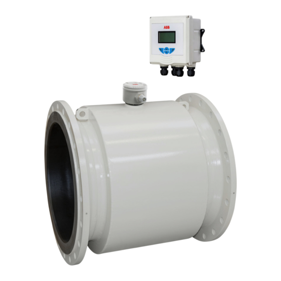
ProcessMaster Water
FEx620
Introduction
—
ProcessMaster
ProcessMaster FEW620 is ABB's new, robust
FEx620
electromagnetic flowmeter for municipal water and
wastewater flow measurement.
Enhanced features simplify commissioning, ease
operation, troubleshooting and maintenance and
overcome skills barriers Digital communication such
as HART or Modbus combined with real-time
diagnostics make ProcessMaster incredibly easy to
work with.
Devices-Firmware Version: 01.13.00
Redefining Electromagnetic
Flow for the Future
Additional Information
Additional documentation on ProcessMaster FEW620,
is available for download free of charge at
www.abb.com/flow.
Alternatively simply scan this code:
My Measurement Assistant
The app that puts ABB measurement device support
at your fingertips:
Advertisement

Related Manuals for ABB ProcessMaster FE 620 Series


Summary of Contents for ABB ProcessMaster FE 620 Series
- Page 1 Digital communication such as HART or Modbus combined with real-time diagnostics make ProcessMaster incredibly easy to work with. My Measurement Assistant The app that puts ABB measurement device support at your fingertips:...
- Page 2 P R O C E S SM A ST E R FEW 62 0 E LE CT RO MAGN E T IC FLOW M ET ER | CI/ F EW62 0 - EN R EV. A Contents Safety ...............3 4.4.9 Mixed system pipeline with corrosion protection and functional earth poten- 1.1 General information and instructions ....3...
- Page 3 Prior to using corrosive and abrasive measurement media, the testing, repair and maintenance of electrical products. operator must check the level of resistance of all parts coming into contact with the measuring medium. ABB will gladly 1.2 Warnings support you in selecting the materials, but cannot accept any liability in doing so.
- Page 4 P R O C E S SM A ST E R FEW 62 0 E LE CT RO MAGN E T IC FLOW M ET ER | CI/ F EW62 0 - EN R EV. A Product identification 2.1 Name plate Nameplate for Meters with MCERTs Calibration Nameplate for Meters with other than MCERTs Calibration Type designation...
- Page 5 P ROCE S S MA STER F EW 62 0 E LEC TR OM AGN ET IC F LOWM ETE R | CI/ FE W620 - EN R EV. A Figure 2 FEX Nameplate, English 2.2 Overview Integral mount design Remote mount design FEW621 FET622...
- Page 6 P R O C E S SM A ST E R FEW 62 0 E LE CT RO MAGN E T IC FLOW M ETE R | C I/F EW 620 - EN R E V. A Transport and storage 3.1 Inspection 3.2.1 Flange devices ≤...
- Page 7 Make sure cavitation (e.g. caused by Valves) does not occur within the Flowmeter tube. • ABB recommends using gaskets made from rubber or rubber- like sealing materials. • Do not remove the sealing plugs in the cable glands until you are ready to install the electrical cable.
- Page 8 P R O C E S SM A ST E R FEW 62 0 E LE CT RO MAGN E T IC FLOW M ETE R | C I/F EW 620 - EN R E V. A ...4 Installation ...4.1 Installation conditions 4.1.8 Inlet and outlet sections 4.1.6 Mounting position Ⓐ...
- Page 9 P ROCE S S MA STER F EW 62 0 E LEC TR OM AGN ET IC F LOWM ETE R | CI/ FE W620 - EN R EV. A 4.1.9 Free inlet or outlet 4.1.11 Installation in the vicinity of pumps Ⓐ...
- Page 10 P R O C E S SM A ST E R FEW 62 0 E LE CT RO MAGN E T IC FLOW M ETE R | C I/F EW 620 - EN R E V. A ...4 Installation 4.2 Installing the sensor ...4.1 Installation conditions 4.1.12 Installation in pipelines with larger nominal NOTICE...
- Page 11 P ROCE S S MA STER F EW 62 0 E LEC TR OM AGN ET IC F LOWM ETE R | CI/ FE W620 - EN R EV. A 4.3.3 Conduit adaptor installation NOTICE Impairment of the IP rating •...
- Page 12 P R O C E S SM A ST E R FEW 62 0 E LE CT RO MAGN E T IC FLOW M ETE R | C I/F EW 620 - EN R E V. A ...4 Installation ...4.4 Grounding the flowmeter sensor 2 Use a copper wire (at least 2.5 mm²...
- Page 13 P ROCE S S MA STER F EW 62 0 E LEC TR OM AGN ET IC F LOWM ETE R | CI/ FE W620 - EN R EV. A 4.4.7 Installation and grounding in pipelines with cathodic corrosion protection The installation of electromagnetic flowmeters in systems with cathodic corrosion protection must be made in compliance with the corresponding system conditions.
- Page 14 P R O C E S SM A ST E R FEW 62 0 E LE CT RO MAGN E T IC FLOW M ETE R | C I/F EW 620 - EN R E V. A ...4 Installation 4.5 Electrical connections 4.5.2 Installing the connecting cables WARNING Observe the following points when routing signal cables:...
- Page 15 P ROCE S S MA STER F EW 62 0 E LEC TR OM AGN ET IC F LOWM ETE R | CI/ FE W620 - EN R EV. A 4.5.3 Connection using a cable conduit 4.5.4 Connection with IP 68 rating ①...
- Page 16 P R O C E S SM A ST E R FEW 62 0 E LE CT RO MAGN E T IC FLOW M ETE R | C I/F EW 620 - EN R E V. A ...4 Installation ...4.5 Electrical connections Potting the terminal box Procedure If the terminal box is to be potted subsequently on-site, a...
- Page 17 P ROCE S S MA STER F EW 62 0 E LEC TR OM AGN ET IC F LOWM ETE R | CI/ FE W620 - EN R EV. A 4.5.5 Electrical connection Connection diagram IMPORTANT (NOTE) The power supply for the optional pre-amplifier is provided via terminals S1 and S2.
- Page 18 P R O C E S SM A ST E R FEW 62 0 E LE CT RO MAGN E T IC FLOW M ETE R | C I/F EW 620 - EN R E V. A ...4 Installation ...4.5 Electrical connections Electrical data for inputs and outputs Modbus Communication Power supply L/N, 1+ / 2-...
- Page 19 Float 64bit ReadOnly Digital outputs 41/42 and 51/52 are not electrically Single TUSIGN8 dynamic F64ROD isolated from each other. Float 32bit ReadOnly dy- If a mechanical counter is used, ABB recommend setting • Single TDOUBLE namic F32ROD a pulse width of ≥30 ms and a maximum frequency (f Unsigned Integer 8bit of ≤ 3 kHz.
- Page 20 P R O C E S SM A ST E R FEW 62 0 E LE CT RO MAGN E T IC FLOW M ETE R | C I/F EW 620 - EN R E V. A ...4 Installation ...4.5 Electrical connections 4.5.6 Connection to integral mount design Figure 32 Connection to integral design Notes: Cable selection: to fix the cable in the gland, cable shall meet 6mm≤...
- Page 21 P ROCE S S MA STER F EW 62 0 E LEC TR OM AGN ET IC F LOWM ETE R | CI/ FE W620 - EN R EV. A 4.5.7 Connection to remote mount design Transmitter side 70 (2.76) Note (0.8) Use wire end sleeves.
- Page 22 P R O C E S SM A ST E R FEW 62 0 E LE CT RO MAGN E T IC FLOW M ETE R | C I/F EW 620 - EN R E V. A ...4 Installation ...4.5 Electrical connections Figure 35 Connection to transmitter in remote mount design (example) NOTICE...
- Page 23 P ROCE S S MA STER F EW 62 0 E LEC TR OM AGN ET IC F LOWM ETE R | CI/ FE W620 - EN R EV. A M 20 mm/ NPT ½ in ① ② 4.6.2 Modbus Communication Terminal for signal cable (see below table) Ground terminal The modbus protocol settings is shown in the following table:...
- Page 24 P R O C E S SM A ST E R FEW 62 0 E LE CT RO MAGN E T IC FLOW M ETE R | C I/F EW 620 - EN R E V. A Commissioning 5.1 Safety instructions 5.2 Write-protection switch, service LED CAUTION and local operating interface...
- Page 25 (50HZ/80HZ)<20VA 24V … 48V DC<10W Dev. Version: 01.13.83 Prot. Class: IP66 NEMA 4% Update: Year: 2024/07 Manufactured by: ABB Engineering (Shanghai) Ltd. China, No. 4528, Kangxin Highway, Kangqiao, Shanghai ProcessMaster FEW622 Model No: FEW622Y0P10150S2R2B1S2A78YY0AC0CMACRACW YJ6K0M6CR08MANC1NF8RCE8C2T CTK1TV3V1SDD Serial No: Tag No:...
- Page 26 The LCD display shows the following display during the requires a PC/notebook and a USB interface cable. startup process: All parameters can also be set using the HART-DTM available www.abb.com/flow and FIM software. The process display is displayed after the startup process. 5.5 Parameterization via the “Easy Set-up”...
- Page 27 P ROCE S S MA STER F EW 62 0 E LEC TR OM AGN ET IC F LOWM ETE R | CI/ FE W620 - EN R EV. A to call up the edit mode. to select “Easy Set-up”. Confirm the selection with to select the desired unit for the volume totalizer.
- Page 28 P R O C E S SM A ST E R FEW 62 0 E LE CT RO MAGN E T IC FLOW M ETE R | C I/F EW 620 - EN R E V. A ...5 Commissioning ...5.5 Parameterization via the “Easy Set- up”...
- Page 29 P ROCE S S MA STER F EW 62 0 E LEC TR OM AGN ET IC F LOWM ETE R | CI/ FE W620 - EN R EV. A 5.6 Measuring range table The flow range end value can be set between 0.02 × Q DN and 2 x Q Nominal diameter Lower range value...
- Page 30 P R O C E S SM A ST E R FEW 62 0 E LE CT RO MAGN E T IC FLOW M ETE R | C I/F EW 620 - EN R E V. A Operation 6.1 Safety instructions The LCD indicator has capacitive operating buttons.
- Page 31 P ROCE S S MA STER F EW 62 0 E LEC TR OM AGN ET IC F LOWM ETE R | CI/ FE W620 - EN R EV. A 6.3 Menu levels Process display Information level Configuration level (Operator Menu) (Configuration) ...Operator Page 1 …n Easy Setup...
- Page 32 P R O C E S SM A ST E R FEW 62 0 E LE CT RO MAGN E T IC FLOW M ETE R | C I/F EW 620 - EN R E V. A ...6 Operation ...6.3 Menu levels 6.3.1 Process display 6.3.2 Switching to the information level (operator menu) On the information level, the operator menu can be used to...
- Page 33 P ROCE S S MA STER F EW 62 0 E LEC TR OM AGN ET IC F LOWM ETE R | CI/ FE W620 - EN R EV. A 6.3.3 Error messages on the LCD display In the event of an error, a message consisting of a symbol and text (e.g.
- Page 34 P R O C E S SM A ST E R FEW 62 0 E LE CT RO MAGN E T IC FLOW M ETE R | C I/F EW 620 - EN R E V. A Diagnosis / error messages Calling up the error description Signal view Additional details about the error that has occurred can be...
- Page 35 P ROCE S S MA STER F EW 62 0 E LEC TR OM AGN ET IC F LOWM ETE R | CI/ FE W620 - EN R EV. A Available diagnostic signals Signal Relates to Example Description Visible with Standard diagnostics Operating conditions...
- Page 36 F090.035 / Electronics ADC RX210 com. error. Bad EMC environment or defective component. Replace the electronics unit or contact Call service. ABB Service. Error no. / Range Text on the LCD display Cause Remedy F086.018 / Electronics Curr.Out 31 / 32 com error.
- Page 37 P ROCE S S MA STER F EW 62 0 E LEC TR OM AGN ET IC F LOWM ETE R | CI/ FE W620 - EN R EV. A Operation outside of specifications (Out Of Spec.) Error no. / Range Text on the LCD display Cause Remedy...
- Page 38 P R O C E S SM A ST E R FEW 62 0 E LE CT RO MAGN E T IC FLOW M ETE R | C I/F EW 620 - EN R E V. A ... 7 Diagnosis / error messages Overview Errors encountered are itemized in tabular form on the following pages.
- Page 39 P ROCE S S MA STER F EW 62 0 E LEC TR OM AGN ET IC F LOWM ETE R | CI/ FE W620 - EN R EV. A Error no. / Range Error text Current output Digital output Pulse output LCD display Error maska-...
- Page 40 • Devices for use in potentially explosive atmospheres results in a short-circuit. may be serviced and repaired by qualified ABB person- For repairs to the liner, electrodes or magnet coil, the nel only. flowmeter must be returned to the manufacturer.
- Page 41 Loss of Ex approval due to replacement of components in devices for use in potentially explosive atmospheres. • Devices for use in potentially explosive atmospheres may be serviced and repaired by qualified ABB person- nel only. • For measuring devices for potentially explosive atmo- spheres, observe the relevant operator guidelines.
- Page 42 • Depressurize and empty the device / piping, allow to All devices delivered to ABB must be free from any hazardous cool and purge if necessary. materials (acids, alkalis, solvents, etc.). Address for returns NOTICE Please contact Customer Center Service acc.
- Page 43 P ROCE S S MA STER F EW 62 0 E LEC TR OM AGN ET IC F LOWM ETE R | CI/ FE W620 - EN R EV. A 10 Recycling and disposal Dismounting Disposal WARNING Risk of injury due to process conditions. Note The process conditions, for example high pressures and Products that are marked with the adjacent sym-...
- Page 44 P R O C E S SM A ST E R FEW 62 0 E LE CT RO MAGN E T IC FLOW M ET ER | CI/ F EW62 0 - EN R EV. A 11 Specifications Note The detailed device data sheet is available in the download area at www.abb.com/flow. 11.1 Permitted pipe vibration In accordance with EN 60068-2-6. Applicable to sensors in remote mount design and sensors in integral mount design.
- Page 45 P ROCE S S MA STER F EW 62 0 E LEC TR OM AGN ET IC F LOWM ETE R | CI/ FE W620 - EN R EV. A 11.2.1 Ambient temperature as a function of measuring medium temperature Integral mount design Measuring medium tempera-...
- Page 46 P R O C E S SM A ST E R FEW 62 0 E LE CT RO MAGN E T IC FLOW M ETE R | C I/F EW 620 - EN R E V. A The limits for the permissible measuring medium temperature (T ) and permissible pressure (P ) are...
- Page 47 P ROCE S S MA STER F EW 62 0 E LEC TR OM AGN ET IC F LOWM ETE R | CI/ FE W620 - EN R EV. A Ⓐ Ⓓ DN 1200-1400, PN 10 DN 2400, PN 10 Ⓐ...
- Page 48 P R O C E S SM A ST E R FEW 62 0 E LE CT RO MAGN E T IC FLOW M ETE R | C I/F EW 620 - EN R E V. A ...Flowmeter sensor ...Material Ⓐ...
- Page 49 P ROCE S S MA STER F EW 62 0 E LEC TR OM AGN ET IC F LOWM ETE R | CI/ FE W620 - EN R EV. A Ⓐ Ⓔ DN 800, Cl 300 DN 1000, Cl 300 Ⓑ...
- Page 50 P R O C E S SM A ST E R FEW 62 0 E LE CT RO MAGN E T IC FLOW M ETE R | C I/F EW 620 - EN R E V. A ...Flowmeter sensor ...Material Ⓐ...
- Page 51 P ROCE S S MA STER F EW 62 0 E LEC TR OM AGN ET IC F LOWM ETE R | CI/ FE W620 - EN R EV. A Ⓐ Ⓔ DN 800, Cl 300 DN 1000, Cl 300 Ⓑ...
- Page 52 The icon on the name plate indicates the following: Note All documentation, declarations of conformity, and certificates are available in ABB’s download area. www.abb.com/flow Trademarks HART is a registered trademark of FieldComm Group, Austin, Texas, USA Hastelloy is a registered trademark of Haynes International, Inc.
- Page 53 P ROCE S S MA STER F EW 62 0 E LEC TR OM AGN ET IC F LOWM ETE R | CI/ FE W620 - EN R EV. A 13 Appendix Return form Statement on the contamination of devices and components Repair and/or maintenance work will only be performed on devices and components if a statement form has been completed and submitted.
- Page 54 We hereby state that the devices/components shipped have been cleaned and are free from any dangerous or poisonous substances. Town/city, date Signature and company stamp Declarations of conformity Note All documentation, declarations of conformity, and certificates are available in ABB’s download area (www.abb.com/flow).
- Page 55 P ROCE S S MA STER F EW 62 0 E LEC TR OM AGN ET IC F LOWM ETE R | CI/ FE W620 - EN R EV. A Notes...
- Page 56 We reserve the right to make technical changes or modify the contents of this document without prior notice. With regard to purchase orders, the agreed particulars shall prevail. ABB does not accept any responsibility whatsoever for potential errors or possible lack of information in this document.
Need help?
Do you have a question about the ProcessMaster FE 620 Series and is the answer not in the manual?
Questions and answers