ABB FEF series User Manual

ABB FEF series User Manual

Electromagnetic flowmeter full-bore flow sensors

Advertisement

User Guide OI/FEF/FEV/FEW–EN Rev. D
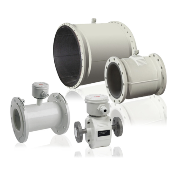
F, V, W Series
Electromagnetic flowmeter
Full-bore flow sensors
The perfect fit for all water
industry applications
Introduction
ABB's full-bore FEF, FEV and FEW electromagnetic
flowmeter sensors are available with either an
AquaMaster 3 or a WaterMaster transmitter.
AquaMaster 3 and WaterMaster are a range of high
performance electromagnetic flowmeters for the
measurement of electrically conductive fluids and are
supplied as factory-configured and calibrated systems.
This User Guide provides end-user details for installation
and connection.
This User Guide should be used in conjunction with the
following publications:
AquaMaster 3 FET200 electromagnetic flowmeter
transmitter User Guide (OI/FET200–EN)
WaterMaster FET100 electromagnetic flowmeter
transmitter User Guide (OI/FET100–EN)
WaterMaster FET100 electromagnetic flowmeter /
transmitter Hazardous areas ATEX / IECEx areas 2,
21 and 22 User Guide (OI/FET100/ATEX–EN)

Advertisement

Table of Contents
loading

Summary of Contents for ABB FEF series

  • Page 1 Full-bore flow sensors The perfect fit for all water industry applications Introduction ABB’s full-bore FEF, FEV and FEW electromagnetic This User Guide should be used in conjunction with the flowmeter sensors are available with either an following publications: AquaMaster 3 or a WaterMaster transmitter.
  • Page 2 We are an established world force in the design and manufacture of instrumentation for industrial process control, flow measurement, gas and liquid analysis and environmental applications. As a part of ABB, a world leader in process automation technology, we offer customers application expertise, service and support worldwide.
  • Page 3: Table Of Contents

    F, V, W Series Electromagnetic flowmeters | Full-bore flow sensors Contents Safety ............................... 2 Electrical Safety ............................. 2 Symbols ................................ 2 Health & Safety ............................. 3 Mechanical Installation ........................4 Unpacking ..............................4 Installation Conditions ........................... 4 Electrical Installation ........................10 Grounding ..............................
  • Page 4: Safety

    F, V, W Series Electromagnetic flowmeters | Full-bore flow sensors 1 Safety 1 Safety Information in this manual is intended only to assist our customers in the efficient operation of our equipment. Use of this manual for any other purpose is specifically prohibited and its contents are not to be reproduced in full or part without prior approval of the Technical Publications Department.
  • Page 5: Health & Safety

    F, V, W Series Electromagnetic flowmeters | Full-bore flow sensors 1 Safety 1.3 Health & Safety Health and Safety To ensure that our products are safe and without risk to health, the following points must be noted:  The safety requirements of this equipment, any associated equipment and the local environment must be taken into consideration during installation.
  • Page 6: Mechanical Installation

    F, V, W Series Electromagnetic flowmeters | Full-bore flow sensors 2 Mechanical Installation 2 Mechanical Installation 2.1 Unpacking Fig. 2.1 Unpacking Caution.  Inspect the flowmeter for damage before installation. Do NOT install a damaged or faulty flowmeter.  When lifting the flowmeter, use the lifting hooks provided or sling under the body of the meter. NEVER lift the flowmeter by the sensor cable terminal connection box –...
  • Page 7 F, V, W Series Electromagnetic flowmeters | Full-bore flow sensors 2 Mechanical Installation Fig. 2.3 Vibration Caution. Do NOT install the flowmeter in a pipeline that may exert excessive movement and twisting forces on the flowmeter, for example, vibration. Fig. 2.4 Localized Heat Caution.
  • Page 8 F, V, W Series Electromagnetic flowmeters | Full-bore flow sensors 2 Mechanical Installation 70 / 130 °C (158 / 266 °F) Max. – 20 °C (– 4 °F) Min. Fig. 2.6 Within Temperature Limits Caution. Ensure the flowmeter is operated within its specified temperature limits. Use flange seals made from a material that is compatible with the fluid and fluid temperatures as required.
  • Page 9 F, V, W Series Electromagnetic flowmeters | Full-bore flow sensors 2 Mechanical Installation Supports Fig. 2.9 Above Ground Caution. Do NOT install the flowmeter in a manner that will subject it to mechanical tension (torsion, bending). If required, support the pipeline. Remember – the flowmeter is a measuring instrument. Fig.
  • Page 10 Caution. When burying a flowmeter, ensure it can be found easily if required (for example, mark the installation position with a post). Installing a protection plate above the meter is also recommended. Note. For further advice when burying flowmeters, contact the ABB Service Organization. Fig. 2.13 Cable Routing Caution.
  • Page 11 F, V, W Series Electromagnetic flowmeters | Full-bore flow sensors 2 Mechanical Installation Fit Gaskets Gaskets Same Size as Pipe Fig. 2.14 Gasket Fitting Caution. Use correctly sized gaskets. Do NOT fit gaskets that will extend into the flow area – the turbulence caused will adversely affect flowmeter accuracy.
  • Page 12: Electrical Installation

    F, V, W Series Electromagnetic flowmeters | Full-bore flow sensors 3 Electrical Installation 3 Electrical Installation 3.1 Grounding Caution. For safety reasons and optimum performance, the flowmeter, pipelines and medium must be correctly bonded and grounded according to regulations. Do not ground cathodically-protected pipelines to an external earth. Note.
  • Page 13 F, V, W Series Electromagnetic flowmeters | Full-bore flow sensors 3 Electrical Installation Fig. 3.2 Metal Pipe with Flange Adaptor Metal Pipe Fluid Contact Ring Plastic Pipe Fig. 3.3 Flanged Metal Pipe to Plastic Pipe Metal Pipe Fluid Contact Ring Plastic Pipe Fig.
  • Page 14 F, V, W Series Electromagnetic flowmeters | Full-bore flow sensors 3 Electrical Installation Fluid Contact Rings Fig. 3.5 All-plastic Pipe Bonding Cables (Supplied) Fluid Contact Rings Fig. 3.6 Pipelines with Cathodic Protection Caution. Do NOT ground cathodically-protected systems. OI/FEF/FEV/FEW–EN Rev. D...
  • Page 15 F, V, W Series Electromagnetic flowmeters | Full-bore flow sensors 3 Electrical Installation Fig. 3.7 AquaMaster 3 Transmitter Mounted in a Chamber (Battery Version Shown) Fig. 3.8 AquaMaster 3 Transmitter Mounted in a Cabinet (Battery Version Shown) OI/FEF/FEV/FEW–EN Rev. D...
  • Page 16 F, V, W Series Electromagnetic flowmeters | Full-bore flow sensors 3 Electrical Installation Power Supply Fig. 3.9 WaterMaster Remote Transmitter Mounted in a Roadside Cabinet OI/FEF/FEV/FEW–EN Rev. D...
  • Page 17: Cable Preparation (Remote Transmitter Only)

    F, V, W Series Electromagnetic flowmeters | Full-bore flow sensors 3 Electrical Installation 3.2 Cable Preparation (Remote Transmitter Only) Caution. Maintain Environmental Protection at all times – See Section 3.3, page 17. To prepare the cable for connection at the transmitter and sensor terminal blocks: 1.
  • Page 18: Sensor Cable Connections (Remote Aquamaster 3 Transmitter Only)

    F, V, W Series Electromagnetic flowmeters | Full-bore flow sensors 3 Electrical Installation 3.2.2 Sensor Cable Connections (Remote AquaMaster 3 Transmitter Only) Caution.  Twist the three screen wires together and sleeve them.  Keep cable pairs twisted.  Make connections only as shown. ...
  • Page 19: Environmental Protection

    F, V, W Series Electromagnetic flowmeters | Full-bore flow sensors 3 Electrical Installation 3.3 Environmental Protection Fig. 3.12 Potting the Sensor Terminal Box Warning.  Potting materials are toxic. Read the manufacturers' instructions carefully before preparing the potting material and use suitable safety precautions. ...
  • Page 20: Specification

    F, V, W Series Electromagnetic flowmeters | Full-bore flow sensors 4 Specification 4 Specification WaterMaster optimized full-bore meter / full-bore meters flow performance (m Standard Calibration – 0.4 % Class 2 High Accuracy Calibration – 0.2 % Class 1 0.4% 0.2% 0.167 0.013...
  • Page 21 F, V, W Series Electromagnetic flowmeters | Full-bore flow sensors 4 Specification WaterMaster optimized full-bore meter / full-bore meters flow performance (GPM) Standard Calibration 0.4 % Class 2 High Accuracy Calibration 0.2 % Class 1 NPS/NB (DN) 0.4% 0.2% (10) 13.8 0.73 0.06...
  • Page 22 F, V, W Series Electromagnetic flowmeters | Full-bore flow sensors 4 Specification AquaMaster 3 FEV2, FEF2 AC-powered Full-bore Sensors – Flow Performance Class 2 specification Class 1 specification Size (0.5%) (GPM) (GPM) (GPM) (GPM) (GPM) (GPM) (GPM) 0.20 0.13 0.32 0.20 (220) (176)
  • Page 23 F, V, W Series Electromagnetic flowmeters | Full-bore flow sensors 4 Specification AquaMaster 3 FEV2, FEF2 Battery / Renewable Energy Full-bore Sensors – Flow Performance Class 2 specification Class 1 specification Size (0.25%) (GPM) (GPM) (GPM) (GPM) (GPM) (GPM) (GPM) 0.25 0.64 (220)
  • Page 24 Transmitter mounting Integral (not FEF) or remote Electrical connections 20 mm glands in. NPT 20 mm armored glands Sensor cable ABB WaterMaster cable available in two forms – standard and armored Maximum length 200 m (660 ft.) OI/FEF/FEV/FEW–EN Rev. D...
  • Page 25 F, V, W Series Electromagnetic flowmeters | Full-bore flow sensors 4 Specification Physical Specification Wetted parts Electrode material Stainless steel 316 L / 316 Ti Super-austenitic steel ® Hastelloy C-22 and Hastelloy (other electrode materials available on request) Potential equalizing rings Minimum of 1 recommended Lining material / potable water approvals Potable Water Approvals...
  • Page 26 F, V, W Series Electromagnetic flowmeters | Full-bore flow sensors 4 Specification Non-wetted parts Flange material Carbon steel DN20 to DN2400 ( to 96 in. NB) Stainless steel DN10 to DN2400 ( to 96 in. NB) SG iron FEV – DN40 to DN150 [1 to 6 in.
  • Page 27: Sensor Dimensions

    F, V, W Series Electromagnetic flowmeters | Full-bore flow sensors 5 Sensor dimensions 5 Sensor dimensions 5.1 FEW – DN10 to 125 ( to 5 in. NB) Dimensions in mm (in.) 77.8 104.5 (3.06) (4.11) (3.86) Ø104 (4.1) (3.5) Fig. 5.1 DN10 to 125 ( to 5 In.
  • Page 28 F, V, W Series Electromagnetic flowmeters | Full-bore flow sensors 5 Sensor dimensions Dimensions in mm (in.) Approx. weight in kg (lb) Mating flange type Integral Remote DN25 PN10 to 40 115 (4.53) 200 (7.87) 268 (10.55) 82 (3.23) 193 (7.6) 148 (5.83) 113 (4.45) 9 (20)
  • Page 29 F, V, W Series Electromagnetic flowmeters | Full-bore flow sensors 5 Sensor dimensions Dimensions in mm (in.) Approx. weight in kg (lb) Mating flange type Integral Remote DN100 PN10 to 16 220 (8.66) 250 (9.84) 314 (12.36) 122 (4.8) 239 (9.41) 194 (7.64) 125 (4.92) 19 (42)
  • Page 30: Few - Dn150 To 400 (6 To 16 In. Nb)

    F, V, W Series Electromagnetic flowmeters | Full-bore flow sensors 5 Sensor dimensions 5.2 FEW – DN150 to 400 (6 to 16 in. NB) Dimensions in mm (in.) 77.8 104.5 (3.06) (4.11) (3.86) Ø104 (4.1) (3.5) Fig. 5.2 DN150 to 400 (6 to 16 in. NB) (FEW) Dimensions in mm (in.) Approx.
  • Page 31 F, V, W Series Electromagnetic flowmeters | Full-bore flow sensors 5 Sensor dimensions Dimensions in mm (in.) Approx. weight in kg (lb) Mating flange type Integral Remote DN250 PN10 395 (15.55) 450 (17.72) 426 (16.77) 198 (7.80) 351 (13.82) 306 (12.05) 235 (9.62) 61 (134) 59 (130)
  • Page 32: Few - Dn450 To 2400 (18 To 96 In. Nb)

    F, V, W Series Electromagnetic flowmeters | Full-bore flow sensors 5 Sensor dimensions 5.3 FEW – DN450 to 2400 (18 to 96 in. NB) Dimensions in mm (in.) 104.5 77.8 (4.11) (3.86) (3.06) (4.1) (3.5) Fig. 5.3 DN450 to 2400 (18 to 96 in. NB) (FEW) Approx.
  • Page 33 F, V, W Series Electromagnetic flowmeters | Full-bore flow sensors 5 Sensor dimensions Approx. weight in kg (lb) Dimensions in mm (in.) Mating flange type Integral Remote DN600 PN10 780 (30.71) 800 (31.50) 565 (22.24) 361 (14.21) 490 (19.29) 445 (17.52) 469 (18.46) 284 (626) 282 (622)
  • Page 34 F, V, W Series Electromagnetic flowmeters | Full-bore flow sensors 5 Sensor dimensions Approx. weight in kg (lb) Dimensions in mm (in.) Mating flange type Integral Remote DN800 JIS 5K 995 (39.17) 1040 (40.04) 654 (25.74) 453 (17.83) 578 (22.76) 538 (21.18) 542 (21.34) 280 (616)
  • Page 35 F, V, W Series Electromagnetic flowmeters | Full-bore flow sensors 5 Sensor dimensions Approx. weight in kg (lb) Dimensions in mm (in.) Mating flange type Integral Remote DN1000 JIS 5K 1195 (47.05) 1300 (51.18) 755 (29.71) 554 (21.81) 679 (26.73) 639 (25.16) 624 (24.57) 441 (970)
  • Page 36 F, V, W Series Electromagnetic flowmeters | Full-bore flow sensors 5 Sensor dimensions Approx. weight in kg (lb) Dimensions in mm (in.) Mating flange type Integral Remote DN1200 JIS 5K 1420 (55.91) 1560 (61.42) 860 (33.85) 659 (25.94) 784 (30.87) 744 (29.29) 802 (31.57) 651 (1432)
  • Page 37 F, V, W Series Electromagnetic flowmeters | Full-bore flow sensors 5 Sensor dimensions Approx. weight in kg (lb) Dimensions in mm (in.) Mating flange type Integral Remote DN1600 1830 (72.05) 2080 (81.89) 1066 (41.96) 865 (34.06) 990 (38.98) 950 (37.4) 1000 (39.37) 1434 (3155) 1432 (3150) (64 in.)
  • Page 38: Fev - Dn40 To 200 (11/2 To 8 In. Nb)

    F, V, W Series Electromagnetic flowmeters | Full-bore flow sensors 5 Sensor dimensions 5.4 FEV – DN40 to 200 (1 to 8 in. NB) Dimensions in mm (in.) 77.8 104. (3.06) (4.11) (3.86) Ø104 (4.1) (3.5) Fig. 5.4 DN40 to 200 (1 to 8 in.
  • Page 39 F, V, W Series Electromagnetic flowmeters | Full-bore flow sensors 5 Sensor dimensions Dimensions in mm (in.) Approx. weight in kg (lb) Mating flange type Integral Remote DN80 EN1092-1 PN10, PN16 200 (7.87) 200 (7.87) 280 (11.02) 51.5 (2.03) 205 (8.07) 156 (6.14) 61 (2.40) 16 (36)
  • Page 40: Fef - Dn80 To 600 (3 To 24 In. Nb)

    F, V, W Series Electromagnetic flowmeters | Full-bore flow sensors 5 Sensor dimensions 5.5 FEF – DN80 to 600 (3 to 24 in. NB) Dimensions in mm (in.) Ø104 (4.1) 86 (3.4) *Base *Dimension C = centre line to base of flowmeter body Fig.
  • Page 41 F, V, W Series Electromagnetic flowmeters | Full-bore flow sensors 5 Sensor dimensions Dimensions in mm (in.) Mating flange type Approx. weight in kg (lb) DN300 (12 in.) ASME B16.5 CLASS 150 485 (19.09) 500 (19.69) 231 (9.09) 317 (12.48) 352 (13.86) 128 (282) ASME B16.5 CLASS 300...
  • Page 42 F, V, W Series Electromagnetic flowmeters | Full-bore flow sensors 5 Sensor dimensions Dimensions in mm (in.) Mating flange type Approx. weight in kg (lb) DN450 (18 in.) ASME B16.5 CLASS 150 635 (25.00) 700 (27.56) 317.5 (12.50) 402 (15.83) 480 (18.90) 160 (352) ASME B16.5 CLASS 300...
  • Page 43: Common Accessories

    F, V, W Series Electromagnetic flowmeters | Full-bore flow sensors 6 Common accessories 6 Common accessories Accessory Item Number WaterMaster AC Fuse F1 Type T 250 mA A/S TR5 B20411 WaterMaster DC Fuse F2 Type T 2 A A/S TR5 B20412 WaterMaster Infra Red Comms Pack MJBX9932...
  • Page 44: Notes

    F, V, W Series Electromagnetic flowmeter | Full-bore flow sensors Notes Notes OI/FEF/FEV/FEW–EN Rev. D...
  • Page 45 F, V, W Series Electromagnetic flowmeter | Full-bore flow sensors Notes OI/FEF/FEV/FEW–EN Rev. D...
  • Page 46 F, V, W Series Electromagnetic flowmeter | Full-bore flow sensors Notes OI/FEF/FEV/FEW–EN Rev. D...
  • Page 47 Repair Centre. — Metals and Minerals — Oil, Gas & Petrochemical — Pulp and Paper ABB Limited Tel: +44 (0)1453 826661 Drives and Motors Fax: +44 (0)1453 829671 — AC and 6 Drives, AC and DC Machines, AC Motors to —...
  • Page 48 With regard Stonehouse to purchase orders, the agreed particulars Gloucestershire GL10 3TA shall prevail. ABB does not accept any responsibility whatsoever for potential errors or possible lack of information in this Tel: +44 1453 826 661 document.

This manual is also suitable for:

Fev seriesFew series

Table of Contents