
Summary of Contents for NKE Multigraphic
- Page 1 MULTIGRAPHIC Item number: 90-60-359 (White) / 90-60-399 (Carbon) USER MANUAL & INSTALLATION SHEET V2.7 Zi de Kerandré – Rue Gutemberg – 56700 – HENNEBONT – FRANCE www.nke-marine-electronics.com...
-
Page 2: Table Of Contents
Configuration of the context keys of the pad (A,B,C,D and Sync) ..........37 2.7.4 Language selection ........................38 2.7.5 Unit selection ..........................38 2.7.6 Maintenance ..........................39 2.7.6.1 Multigraphic node address in the Topline system................39 2.7.6.2 Auxiliary inputs ............................ 40 2.7.6.3 Topline Instrument system ........................43 2.7.6.4 Firmware ............................. 44 2.7.6.5 Memory ............................... - Page 3 OPLINE BUS AND ......................84 ODE ADDRESS FOR THE ULTIGRAPHIC NMEA ..................84 ONNECTING TO A SOURCE AND CONFIGURATION ..................84 NSTALLATION AND CONFIGURATION OF THE YROPILOT MULTIGRAPHIC SPECIFICATIONS ......................86 EVENTS MESSAGES..........................87 FIRMWARE EVOLUTION OF MULTIGRAPHIC ..................89 50_Afficheur_Multigraphic_um_UK_27...
-
Page 4: Overview
A.I.S. receiver connected. • Interface to NMEA 183 devices to provide relevant data to the Topline bus. 2 OPERATION The Multigraphic offers 10 buttons to control the display, access the menus and control the autopilot. Key descriptions... - Page 5 • PAGE Successive presses will scroll through the pre-set data pages, the pilot page and the setting page. Press and hold (at least 3 seconds) to open the Menu page. • OK A single press confirms the current selection, or opens specific setup features on some pages.
-
Page 6: Menu Page
2.2 Menu page When the Multigraphic is used for the first time it displays a screen with a menu providing access to: • the page builder function • the sensor settings • the alarm settings • the pilot settings • the Performance page setup •... -
Page 7: Page Building Wizard
2.3 Page building wizard The Multigraphic has been designed to allow the user to customise pages. 10 pages can be set up according to the user’s preference with the first 5 pre-set to default settings. To build a page, first select the « Page » icon in the menu:... - Page 8 Select the page you want to build or edit with the up and down arrows . Empty pages are grayed out. Once you have made your selection, confirm with Page format You can choose between different layouts for the page. Press , a list will appear.
- Page 9 The following page layout templates are available: 1 line 2 lines 3 lines 3 lines 4 lines 4 lines 6 lines 4+4 page Waypoint page XTE page 1+1 page A.I.S. data Regatta page Once you have made a choice, press to confirm.
- Page 10 Edit a page This setting selects the data that will be displayed on the selected page FOLLOWING to accept the current data in that selected part of the screen (only for multiple line pages) and go to the next page partition. MODIFY to change the information and the colour in which it will be displayed by selecting from a list.
- Page 11 Press to save the page. Select Name with the pad and press the button to access the virtual keyboard. Use the pad keys to select letters and press to confirm your choice. Repeat the action for each entry. Toggle between numbers and letters. Caps lock.
-
Page 12: Display
Enter, to confirm the name and save the page. Displayed The new page is visible by default. Press to hide the page. Unhidden Hidden Edit name Edit the page name with the virtual keyboard. 2.4 Display pages Scroll through the build pages, the pilot and menu pages by pressing the button with successive presses. - Page 13 Using the Remote Display transmitter The Remote Display Transmitter can be used to display the different pages constructed, to access the menu, etc. The operation is the same as the Multigraphic keyboard. To select the Multigraphic, press and hold the page button on the transmitter for about 5 seconds.
- Page 14 “NMEA settings”). For example, software such as ADRENA feeds the system with 8 functions depending on the race course legs and this information can be read on these pages. They can be displayed on any Multigraphic in the Topline network. The 8 available channels are named DYN 1 to DYN8.
-
Page 15: Multigraphic Operation With The Gyropilot 2 Processor
2.5 Multigraphic operation with the Gyropilot 2 processor Gyropilot is an automatic pilot designed to steer the boat. It is intended to assist the helmsman and should never be used without state of the art navigation equipment handled by a qualified navigator. -
Page 16: Useful Buttons For Controlling Of The Gyropilot
2.5.1 Useful buttons for controlling of the Gyropilot Press once to engage the pilot on the current course relevant to the pilot mode selected. In compass mode it will be the compass heading at the time you press the button and in wind mode it will be the wind angle at the time you press the button. -
Page 17: Pilot
2.5.2 Pilot Page selection 2 different pilot pages are available : analogue format or digital format (see § 2.3 for customizing) 2.5.2.1 Gyropilot page Gain value adjustable with the up and down Access arrows on the pad pilot mode with Sensor identification Course to steer... -
Page 18: Pilot Modes
The true wind mode is particularly well adapted to downwind conditions in waves. These are the conditions where the nke pilot demonstrates its true capability. If apparent wind was used you would get the following issues:... - Page 19 True wind software add-on A code is required to activate the true wind mode function. Please contact your nke dealer to get this code. The code number is linked to each Gyropilot 2 processor, your dealer will need your processor’s serial number to issue the code for the software add-on.
-
Page 20: Pilot Settings
Autopilot in GPS mode In GPS mode the Gyropilot steers the boat to a route provided by the GPS or the navigation software connected to the NMEA input of your Topline system. 2.5.4 Pilot settings Select the pilot’s settings page: Rudder coefficient Principle: the Gyropilot processor automatically adjusts the value of the rudder angle to apply which is proportionally opposite to the boat speed. - Page 21 Counter rudder / gain When you are steering you will often apply “counter rudder” by moving the rudder to the opposite direction allowing the heading to be maintained without overshoot. The pilot can be set up to control the boat in a similar way and the importance of this feature will depend on the type of boat and sea conditions.
- Page 22 Tacking angle Set the tacking angle value for automatic tack performed by the Gyropilot. For the compass mode the tacking angle can be set between 70° and 115° (by 5° steps). The default setting is 100°. Tack speed The speed at which tacks are performed by the Gyropilot can be set from 1° per second to 32°...
-
Page 23: Gyropilot Operation
(port / starboard). 2.5.5 Gyropilot operation This section of the manual describes the use and operation of the MULTIGRAPHIC once installed and calibrated. For installation and calibration, refer to the installation section, page 70. - Page 24 Topline bus to steer the boat on a set Apparent Wind Angle. This mode is mainly used while sailing upwind. The following graphic shows the pilot page as it will be displayed on the Multigraphic when the Gyropilot is engaged in Apparent Wind mode. 50_Afficheur_Multigraphic_um_UK_27...
- Page 25 « true wind ». Once this mode has been selected the pilot steers the boat to a set true wind angle calculated by the Gyropilot processor. The following graphic shows the pilot page as it will be displayed on the Multigraphic when the Gyropilot is engaged in True Wind mode Gain Mode...
- Page 26 This mode can be used to check the drive unit or just to lock the rudder in a given position. The following graphic shows the pilot page as it will be displayed on the Multigraphic when the Gyropilot is engaged in Rudder mode Mode Gain...
- Page 27 Using the GPS mode In GPS mode the Gyropilot steers the boat to a route provided by the GPS or the navigation software connected to the NMEA input of your Topline system. To achieve this, the GPS or the navigation software must feed the system with the following NMEA sentences: - $xxXTE : cross-track error and - $xxBWC : bearing and distance to waypoint (DTW and BTW) or...
-
Page 28: Pilot Setup Saving And Recall
2.5.6 Pilot setup saving and recall Up to 10 pilot setups can be saved and used at any time. For example, you can save a setup for upwind conditions and another one for downwind. Saving a pilot setup: Recall a pilot setup: 50_Afficheur_Multigraphic_um_UK_27... -
Page 29: Pilot Alarm
The alarm will sound when the wind angle variation is greater than the set value for more than 30 seconds in compass mode and when the heading variation is greater than the set value for more than 30 seconds in wind mode. The Multigraphic will display a message and sound beeps. -
Page 30: Pilot Page On Remote Display
“Auto”, “± 10°”, “± 1°” or “tack” on a remote control or a Gyropilot control display. 2.6 Operation of the Multigraphic as multifunction display Multigraphic is a multifunction display from the TOPLINE range of products. It connects to the TOPLINE bus on your system and displays all data available on the bus. - Page 31 This modification has not been saved and the previous layout will return the next time the system is powered on. Saving a modification to a page You can edit a page and save modifications permanently. Example: on the first page now choose to display apparent wind angle instead of the bus Voltage and save this new configuration.
-
Page 32: Setting Parameters
2.7 Setting parameters Press and hold to display the main menu in which you select for the «Parameters» page. Use the up and down arrows of the pad to select and to confirm. 2.7.1 Display settings The Display Settings menu gives access to: •... -
Page 33: Backlighting
The backlightighing can toggle automatically between Night and Day settings, driven by a light sensor, or can be manually set. Backlight settings can be adjusted as required for each Multigraphic independently. Backlight setup process: Auto: Backlighting toggles automatically between Night and Day settings, driven by a light sensor. -
Page 34: Setting Night And Day Modes
2.7.1.2 Setting Night and Day modes Setting procedures are identical for Day mode and Night mode. Backlight intensity setting: Skin settings You can choose between 8 Skins for Day and Night modes. The default Skins are white for Day and black/red for night. The new eight skin is Black/white. Some skins are more appropriate than others, depending of the reading angle. -
Page 35: Display's Standby Timing
A time can be set up to 30 minutes. When the selected time is reached the display will be put in a “sleep mode” for power saving. The Multigraphic will keep working and the screen can be resumed with the simple press of any key or selecting the display on a remote control. -
Page 36: Keypad Beep
2.7.1.5 Keypad Beep Press and hold to enter the setting. After the beep keys inactive « », no beep is emitted when a key press. For reactivate the key beep do the same manipulations to find the key minder active logo « ». -
Page 37: Data Logging: "Stripcharts" Settings
4 different sets of data can be logged simultaneously over a 48 hour period with a 15 seconds log rate. The logged data can be displayed on stripcharts on the “Multigraphic”. “stripcharts” settings process: 2.7.3 Configuration of the context keys of the pad (A,B,C,D and Sync) The A, B, C, D and Sync keys allow in a context, to directly display preprogrammed pages on all displays. -
Page 38: Language Selection
Your Multigraphic can be set to display menus in various languages. Language setting process: 2.7.5 Unit selection The Multigraphic can be set to use various units for boat speed, depth, air temperature, sea temperature and wind speed. Depending on the information selectable units are “knots”, “meters per second”, kilometres per hour”, “degrees Celsius”... -
Page 39: Maintenance
« Master » and manages the whole system. If there is already a Master », the Multigraphic will get an address different from 1 and it will behave as « Slave ». This process is carried out automatically: if there is no «... -
Page 40: Auxiliary Inputs
Topline system. Baud rate is automatically detected between 4800 or 38400 Bauds. Note: NMEA data coming from an A.I.S receiver connected to the Multigraphic NMEA input is directly available on the Multigraphic and does not require set up. NMEA input settings: 50_Afficheur_Multigraphic_um_UK_27... - Page 41 All NMEA channels are activated by default. You can choose to inhibit some channels. This is done by selecting the chosen channel and pressing Here, Speed Over Ground is inhibited Press finish NMEA settings and update the channels on the Topline bus accordingly. List of the channels and associated NMEA 0183 sentences.
- Page 42 V_FOND CAP_FOND (vrai) C_WP_OD B_PILOT ANNMOIS R_COMPASS R_ANG_VENT_APP LAT_DEGMIN LAT_MILMIN LON_DEGMIN LON_MILMIN V_WP VIT_CIBLE CAP_AUTRE_BORD ANGLE_OPT_VENT REND_PRES REND_POLAIRE ANGLE_OPT_CMG ANGLE_OPT_VMG GAIN_ROUTE_CMG GAIN_ROUTE_VMG DIREC_COURANT VITES_COURANT PRESS_ATMOS DECL_MAG Waypoint name RMB et BWC DYN1 PNKEA,,1 DYN2 PNKEA,,2 DYN3 PNKEA,,3 DYN4 PNKEA,,4 DYN5 PNKEA,,5 DYN6 PNKEA,,6...
-
Page 43: Topline Instrument System
R_SPEEDO 2.7.6.2.3 Stats GPS When a HF GPS is connected to the NMEA input of the Multigraphic an additional menu appears "GPS Stats" in the external devices menu. This menu displays the visible satellites and their signal levels. It is possible with a NMEA 0183 GPS to obtain this page if it sends the GGA, GSA and GSV frames which activate this page. -
Page 44: Firmware
2.7.6.3.1 Utility for the WIFI box When the nke “WIFI box” is connected to the Topline bus, the following can be displayed: • Editable SSID • WPA key • editable WIFI channel • IP for the WIFI box • WIFI box port Please refer to the WiFi Box manual. -
Page 45: Simulator
2.7.6.6 Simulator There is a simulator available in the Multigraphic. Once activated, it sends random data to the Topline bus and the symbol is shown to highlight that the system is working in simulation mode. Simulator menu: 2.7.6.7 Autotest Autotest is useful to check the Multigraphic. This procedure verifies the following functions step by step: •... - Page 46 All keys 50_Afficheur_Multigraphic_um_UK_27...
-
Page 47: Sensor Settings
2.8 Sensor settings Go to the main menu by pressing and select to display the « sensors » page. All sensors connected to the Topline bus can be calibrated from this menu. Settings are different for each sensor. Refer to the sensor’s manual for more information. Main settings: Filter: the filter takes the data average value to set a data refresh rate. -
Page 48: Calibration Wizard
2.8.1 Calibration wizard Calibration wizards are available to help you calibrate the apparent wind angle, the boat speed and a fluxgate compass (not available for the REGATTA compass). 2.8.1.1 Apparent Wind Angle calibration wizard Sail 4 legs upwind to measure the average wind angle on each tack. A wind vane offset will be calculated and applied to correct the Apparent Wind Angle. -
Page 49: Boat Speed Calibration Wizard
2.8.1.2 Boat speed calibration wizard The boat speed is calibrated with the speed over ground as reference. You have to sail 0.5 nM on a constant heading and then sail back (180°) the same distance. The new calibration is processed from the current calibration value already saved (there is no need to reset the calibration value to 1). -
Page 50: Compass Auto-Adjustment
This page displays the current calibration value (old correction), the new calibration value (new correction), the factors calculated from the runs (ratio FW/BW) and the correction factor for boat speed. 2.8.2 Compass auto-adjustment Some magnetic deviation errors are unique to each boat, due to the magnetic environment. -
Page 51: Compass Deviation Table
While swinging the fluxgate, or Regatta compass, you can display the Course Over Ground in a window to show the progress of the manoeuvre. In the case of the Regatta compass without COG data on the bus the progression will not be displayed and you will need to follow the procedure from the bowl compass at the helm. -
Page 52: Compass Adjustment Wizard
This method can only be used with the fluxgate compass and 9X compass It consists of sailing the boat on the nke compass heading (+/-5°), comparing this heading with the magnetic heading over the ground and noting the value every 30° to determine the values for the correction table. -
Page 53: Drift Angle
Press “OK” to save the new correction. You can highlight “Abort” and press “OK” if you want to cancel a correction. Repeat this operation every 30° to fill the whole correction table. The compass will have its deviation curve implemented once this table is completed. -
Page 54: Sensors Access Code
i.e. the drift with 17° heel angle and 7 knots boat speed is: 10 x 17° / 7 + 0° = 3.46° drift angle As an alternative to this formula, an offset value can be set to force the drift angle by setting the factor to 0 and entering the desired value of the drift angle as an offset. -
Page 55: Alarms Settings
Procedure to unlock the sensor menu: 2.9 Alarms settings Press and hold to display the main menu from which you select display the « Alarm » page. Setting alarms allow keeping watch on the value of set channels. Once the set value is reached a message is displayed and an audible signal is emitted. - Page 56 50_Afficheur_Multigraphic_um_UK_27...
-
Page 57: Procedure For Alarm Setting
2.9.2 Procedure for Alarm setting Once you have selected the data to watch the alarm system must be activated on the Topline bus. A status window will show before activation. 2.9.3 Procedure for deactivation of Alarms Once alarms are deactivated no data will be monitored by the system. 50_Afficheur_Multigraphic_um_UK_27... -
Page 58: Activation Of An Alarm
10 minutes the conditions are still met for the alarm to activate, the window will resume. From version 2.4 of Multigraphic it is possible to relay Sensor alarms to the V3.1 or higher radio receiver. For this it is necessary to validate an alarm, that the alarm status is valid. - Page 59 XTE page Distance to Waypoint Speed over ground Waypoint And Name Indicator direction for go back to the course Cross track error Heading to Waypoint Course over ground 50_Afficheur_Multigraphic_um_UK_27...
- Page 60 This information is available to any ship or traffic control station within the signal reception area. The NMEA input of the Multigraphic can be connected to an A.I.S. receiver to display A.I.S. targets and to calculate collision risks.
-
Page 61: A.is. Targets Symbol
2.11.1 A.IS. targets symbol The green targets are non-hazardous vessels and they are not inside the alert limits you have defined. The front arrow represents the vessels movement. Warning: If you have not set any alert limits, all the targets will appear with a green symbol, even those on a collision course. -
Page 62: Setting The Radar-Like Scale
Multigraphic is 12M. 2.11.3 Setting A.I.S. alarms The Multigraphic features an alarm processor which, once connected to an A.I.S. receiver or transponder, calculates bearing and distance of a target vessel, the CPA (Closest Point of Approach), the CPA bearing and the TCPA (Time to Closest Point of Approach). -
Page 63: Collision Avoidance Calculation
CPA being below 4 miles and the TCPA calculated value being below 20 minutes, the Multigraphic triggers an alert. From version 2.4 of Multigraphic it is possible to relay AIS Alarms on the V3.1 radio receiver. To do this, an alarm must be validated on the AIS page and the Alarm status is valid. -
Page 64: Dangerous Targets List
2.11.5 Dangerous targets list The list of targets representing a threat shows all targets that are in the alarm zone. They are sorted by threat level. For each of them the MMSI number, the bearing, the distance, the CPA and the TCPA are displayed. Any target can be selected from the targets list and pressing displays it on the A.I.S. -
Page 65: Graphs Display
2.12 Graphs display Some data coming from the Topline sensors can be displayed as a graph. All data stored in the log can be displayed as a graph with a zoom function ranging from 5 minutes to 48 hours depending on the time they have been logged. Data which is not stored in the log can be displayed on a 5 minutes scale. -
Page 66: Change The Graph Scale
2.12.1 Change the graph scale 8 scale levels are available for data which is stored in the log: 5 minutes, 20 minutes, 1 hour, 2 hours, 6 hours, 12 hours, 24 hours and 48 hours. Procedure to change the graphs scale: 2.12.2 Resetting the graph Resetting the graph erases the data in the log. -
Page 67: Displaying Other Data
2.12.3 Displaying other data From a graph page it is possible to display other data. This does not affect the page construction. It is a temporary display which will not be saved. 2.12.4 Navigating in the graph Use the left and right arrows to display specific sections of the graph through logged data once you have set the graph’s scale (§... -
Page 68: Race Timer
2.13 Race timer The race timer works as a countdown before the start of a race. Two different race procedures can be set up as « T1 » and « T2 ». The default settings are 5 minutes for « T1 » and 4 minutes for « T2 ». At the end of the countdown, a short audible signal is emitted at the 10 last seconds signal and the start time triggers a long audible signal. -
Page 69: Setting The Race Timer
• Starting the race timer with remote The timer data must be selected before starting the race timer. For load race timer press « OK » 3 seconds. For start short press on « OK ». At any time during countdown press on «... -
Page 70: Performance Functions
2.14 Performance functions 2.14.1 Calculation of the current The Multigraphic will automatically calculate the current when it is set as a master. The following channels are created: Speed of measured current (in knots). Direction of measured current (in degrees True). -
Page 71: True Wind Angle Table
2.14.2.1 True wind angle table The true wind angle table allows correction of the true wind angle value without researching the causes of angle’s errors. It corrects all repeatable errors (twist, flow over-speed downwind, sensor). The true wind data is calibrated by logging the true wind direction differences from one tack to another repeatedly. -
Page 72: True Wind Speed Table
2.14.2.2 True Wind Speed table Even when placed one meter above the mast head on top of a carbon arm the wind sensor will measure a flow altered by the effects of the mainsail. When sailing downwind the mainsail causes an acceleration of the air flow at the mast head and when the boat is heeling the measurement of the wind will be altered. -
Page 73: Activating The True Wind Tables
2.14.2.3 Activating the true wind tables The corrections will be implemented once the true wind tables are activated. 2.14.2.4 Resetting the tables The “RESET TABLE” command can be used at any time to reset the table to the default values. 2.14.3 Statistics for the last hour True Wind Direction, average of the true wind direction during the past hour. -
Page 74: Regatta Page
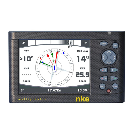
2.15 Regatta page 2.15.1 Presentation of the Regatta page Starting mode screen True Wind indicator This indicator gives a quick and accurate view of the true wind direction behaviour: o Value range o Current value o Average o Values variations’ standard deviation 50_Afficheur_Multigraphic_um_UK_27... - Page 75 Description of the example featured in this page: The current wind direction is 7°magnetic, the left end is 0° and the right end is 29°. The average value is in the centre of the colour shading which covers the extend of the standard deviation of the wind shifts.
- Page 76 16° shows the favourable angle value. In this example the wind angle to the right side of the perpendicular to the line is 16°. By knowing the start line length, the MultiGraphic can calculate the gain to windward difference between both ends of the line.
-
Page 77: Set The Start Line
2.15.1.1 Set the start line The start line’s ends can be entered using the GPS position (antenna) or bearing and distance. Entering the GPS position: Sail as close as possible to the mark at low speed and validate the position when the GPS antenna matches the marks position as much as possible. -
Page 78: Description Of The Tactical Screen
Distance to Waypoint Distance and bearing to the n°1 mark can be displayed with the distance and bearing to Waypoint channels of the Topline bus once the Multigraphic’s NMEA input has been set up. The Distance and Bearing to Waypoint channels must be free (no other interface set up for the NMEA input). - Page 79 TWA Target (polar) The 4 data displayed in the example above are AWA, TWD mag, VMG and TWS. They can be selected by the user with the key pad Direction reference selection parameter (True or magnetic) From the Tactical page it is possible to change the reference for the course over ground, bearing to waypoint and heading.
-
Page 80: Instruments Calibration
2.16 Instruments calibration 2.16.1 Introduction Accurate and realistic data requires good calibration of the sensors. Without calibration you will not get accurate data for true wind direction, true wind speed, measured drift,... Poor calibration will produce mistakes that will affect your tactical decisions. It is recommended to proceed to calibration in moderate wind conditions and steady water. -
Page 81: Installation
3 INSTALLATION This section describes the installation and configuration of the Multigraphic as well as setting the parameters for an installation with a Gyropilot 2 processor. Refer to the Gyropilot 2 manual for the full pilot installation (drive unit, processor, rudder feed-back…). -
Page 82: Bulkhead Installation
3.4 Bulkhead installation Check that the surface is clean, flat and straight. There must be enough space on the other side to run the cable. Drill at ∅15 and Ø22 according to the drawing below, Clean the surface with alcohol. Use a silicone on the fixation perimeter Pull the cable through the ∅22 mm hole, Place the display and hand bolt. -
Page 83: Connection To The Topline Bus And Nmea
3.5 Connection to the Topline bus and NMEA 1. Run the bus cable from the Gyropilot Graphic to the TOPLINE junction of your system. 2. Connect the cable in the junction box. nke Gyrop lot 2 COMPASS FLUXGATE Calculateur Gyro2... -
Page 84: Node Address For The Multigraphic
3.6 Node address for the Multigraphic At the first power on, you must give a node address to the Multigraphic to enable it to work on the system’s bus. The default address is 0. When the unit is given an address it will take a place in the system to be listed in the units working on the TOPLINE bus: −... - Page 85 Procedure: Warning The Gyropilot can only perform the automatic tack if the rudder ends are perfectly symmetrical. While setting the rudder ends, check that this is the case. Port lock to midship and starboard lock to midship must be the same. 50_Afficheur_Multigraphic_um_UK_27...
-
Page 86: Multigraphic Specifications
4 MULTIGRAPHIC SPECIFICATIONS Feature Value Dimensions With sun cover: 196 x 122 x 28mm (length x height x depth) Without sun cover: 192 x 118 x 23mm ((length x height x depth) Weight 800 g (with 6 m cable and sun cover) Power supply 8V –... -
Page 87: Events Messages
5 EVENTS MESSAGES Message at system start up, indicating the Multigraphic address. Multigraphic being set as “Master”, when the system creates the list (search all sensors and displays in the bus), it displays addresses for slave displays. The “master” display is unplugged or out of order. - Page 88 This page is shown when the Man Over Board function has been triggered. The dead reckoned distance and bearing to the man over board are displayed together with the boat’s course over ground. The timer is triggered to give the time from event.
-
Page 89: Firmware Evolution Of Multigraphic
Fixed a bug of the freeze of screen Fixed of the bug which could slow down the functioning of Multigraphic during an important flow AIS. New Tactical page for the assistant to the regatta The Pilot page can be temporarily displayed on a remote... - Page 90 Fixed the bug displaying the depth in alarm. Note: If you don't understand some points, or have some suggestions to improve this documentation, you can fill a note on https://www.nke-marine-electronics.fr/ Thank you for your contribution. YOU CAN HELP PROTECT THE ENVIRONMENT!
Need help?
Do you have a question about the Multigraphic and is the answer not in the manual?
Questions and answers