Digi ConnectCore 6UL Hardware Reference Manual
Sbc express
Hide thumbs
Also See for ConnectCore 6UL:
- Hardware reference manual (135 pages) ,
- Hardware design manuallines (16 pages)
Table of Contents
Advertisement
Quick Links
Advertisement
Table of Contents

Related Manuals for Digi ConnectCore 6UL


Summary of Contents for Digi ConnectCore 6UL
- Page 1 ConnectCore® 6UL SBC Express Hardware Reference Manual...
- Page 2 Information in this document is subject to change without notice and does not represent a commitment on the part of Digi International. Digi provides this document “as is,” without warranty of any kind, expressed or implied, including, but not limited to, the implied warranties of fitness or merchantability for a particular purpose.
- Page 3 To provide feedback on this document, email your comments to techcomm@digi.com Include the document title and part number (ConnectCore 6UL SBC Express Hardware Reference Manual, 90001520 B) in the subject line of your email. ConnectCore 6UL SBC Express Hardware Reference Manual...
-
Page 4: Table Of Contents
USB device Expansion connector Pinout of the Raspberry Pi expansion connector Grove connectors User LED and button Specifications Electrical specifications Supply voltages Power consumption Mechanical specification Top view Bottom view Profile view Environmental specifications ConnectCore 6UL SBC Express Hardware Reference Manual... - Page 5 Regulatory information Maximum power and frequency specifications Europe Declarations of Conformity CE mark ConnectCore 6UL SBC Express Hardware Reference Manual...
-
Page 6: About The Connectcore 6Ul Sbc Express
About the ConnectCore 6UL SBC Express The ConnectCore 6UL SBC Express is a compact board featuring the Digi ConnectCore 6UL System-on- module (SoM). The ConnectCore 6UL System-on-module integrates an NXP i.MX6UL application processor with DDR3 and NAND flash memory, WLAN/Bluetooth, power management IC, a crypto- authentication security chip, and a Microcontroller Assist (MCA) for additional functionality. -
Page 7: Placement
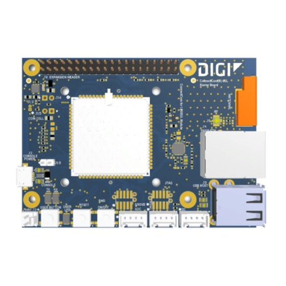
Expansion connector that can accommodate Raspberry PI Hat boards Three Grove connectors providing digital, ADC, and I2C connectivity User interface: One user LED One user button Dimensions: 87 mm x 63 mm Placement Top view ConnectCore 6UL SBC Express Hardware Reference Manual... -
Page 8: Bottom View
About the ConnectCore 6UL SBC Express Placement Bottom view ConnectCore 6UL SBC Express Hardware Reference Manual... -
Page 9: Block Diagram
About the ConnectCore 6UL SBC Express Block diagram Block diagram ConnectCore 6UL SBC Express Hardware Reference Manual... -
Page 10: Interfaces
Interfaces Power connector Coin cell connector Boot mode Power and reset buttons JTAG Console port MicroSD 10/100 Mbps Ethernet Embedded antenna USB host USB device Expansion connector Grove connectors User LED and button ConnectCore 6UL SBC Express Hardware Reference Manual... -
Page 11: Power Connector
Power connector Power connector A 5V power connector provides power to the ConnectCore 6UL SBC Express. A 2-pin, 2.54 mm pitch, latched vertical connector offers a power rail to the whole system (the board plus the ConnectCore 6UL module.) You can also power the board from the USB console port. -
Page 12: Coin Cell Connector
Coin cell connector Coin cell connector The ConnectCore 6UL SBC Express can be assembled with a 2-pin, 1.25 mm pitch straight connector that powers the real-time clock (RTC) interface with an external coin cell or supercapacitor when the main supply is off. When the main power supply rail is connected, it powers the RTC. You can supply the RTC with a primary Lithium cell (non-rechargeable), a secondary Lithium cell (rechargeable), or a supercap. -
Page 13: Boot Mode
Boot mode Boot mode By default, the ConnectCore 6UL module boots from internal board settings, allowing it to boot from internal NAND memory. For advanced functionality, the ConnectCore 6UL SBC Express provides two resistors to configure the SOM boot mode. ... -
Page 14: Boot From Usb
Boot mode Boot from USB You can close the USB mode jumper on the ConnectCore 6UL SBC Express to force the i.MX6UL to boot from the source programmed in the one-time-programmable (OTP) bits. If the boot configuration OTP bits are not programmed, the CPU falls back to booting into USB debug mode. -
Page 15: Power And Reset Buttons
Interfaces Power and reset buttons Power and reset buttons The power button on the ConnectCore 6UL SBC Express is connected to the on-module MCA, which provides the following functionality: Board status Power button action Response Short press Power on ON or SLEEP... - Page 16 Interfaces Power and reset buttons Note You can configure the duration of some power button actions. See the ConnectCore 6UL SBC Express documentation ConnectCore 6UL SBC Pro documentation for more information. ConnectCore 6UL SBC Express Hardware Reference Manual...
-
Page 17: Jtag
JTAG JTAG The ConnectCore 6UL SBC Express provides two options for accessing the i.MX6UL JTAG debug port. The first option is a 2x5, 1.27mm pitch pin header on the top side of the board that, by default, is not populated. The following table shows the pinout of the JTAG connector: Pin Signal name Description 3.3V... - Page 18 The second option is the Tag Connect footprint on the bottom side of the board. This Tag Connect is compliant with the ARM 10-pin standard. The JTAG Tag Connect is highlighted in the following picture: ConnectCore 6UL SBC Express Hardware Reference Manual...
-
Page 19: Swd
Interfaces As in the JTAG debug interface, the ConnectCore 6UL SBC Express provides two options for programming and debugging the Microcontroller Assist of the ConnectCore 6UL System-on-module. The first option is a 2x5, 1.27 mm pitch pin header footprint on the top side of the board that, by default, is not populated. - Page 20 J18 SWD connector manufacturing part number: SAMTEC FTSH-105-01-F-DV The second option is the ARM 10-pin standard-compliant Tag Connect footprint on the bottom side of the board. The SWD Tag Connect is highlighted in the following picture: ConnectCore 6UL SBC Express Hardware Reference Manual...
-
Page 21: Console Port
Console port Console port The ConnectCore 6UL SBC Express uses a USB micro AB-type connector as a console port for debugging and configuration. The USB signal passes through a USB-to-serial UART bridge and generates TTL signals connected to the i.MX6UL processor. The ConnectCore 6UL module uses the UART5 port as the console port. - Page 22 Interfaces Console port Console default settings: Baud rate: 115200 Data: 8 bit Parity: none Stop:1 bit Flow control: none ConnectCore 6UL SBC Express Hardware Reference Manual...
-
Page 23: Microsd
CPU. The following table shows the pinout of the microSD socket: Pin Signal name Description SD2_DATA2 Serial data 2 SD2_DATA3 Serial data 3 SD2_CMD Command line 3.3V power line SD2_CLK Serial clock SD2_DATA0 Serial data 0 SD2_DATA1 Serial data 1 ConnectCore 6UL SBC Express Hardware Reference Manual... -
Page 24: 10/100 Mbps Ethernet
Transmit pair data (+) Transmit pair data (-) Receive pair data (+) Center tap Center tap Receive pair data (-) LED1_P Green LED anode LED1_N Green LED cathode LED2_P Yellow LED anode LED2_N Yellow LED cathode ConnectCore 6UL SBC Express Hardware Reference Manual... -
Page 25: Ethernet Phy Power Management
Ethernet PHY power management You can manage power consumption of the system by enabling or disabling Ethernet PHY power through a power switch. The dedicated GPIO connected to the power switch is GPIO3_IO02. ConnectCore 6UL SBC Express Hardware Reference Manual... -
Page 26: Embedded Antenna
Embedded antenna Embedded antenna An embedded antenna placed on a corner of the ConnectCore 6UL SBC Express supports the wireless and Bluetooth functionality of the ConnectCore 6UL module. A surface mount coaxial connector is also connected to the PCB antenna through a 0 ohm resistor. This on-board antenna is connected to the ConnectCore 6UL module using a U.FL-to-U.FL cable. -
Page 27: Usb Host
USB host USB host Two USB host interfaces are located on the right side of the ConnectCore 6UL SBC Express over a stackable dual USB A-type connector. Both USB hosts can operate at high, full, and low speed. The following table shows the pinout of the dual stackable USB host connector:... -
Page 28: Usb Device
Interfaces USB device USB device The ConnectCore 6UL SBC Express has a micro-AB type receptacle for a USB device connection. The following table shows the pinout of the USB device connector: Pin Signal name Description USB_OTG1_FIL_N USB differential data signal (-) - Page 29 CAUTION! The USB device shares the USB_OTG1 instance of the i.MX6UL processor with the lower USB host port of the stacked connector. Connecting two devices to the USB_OTG1 port at the same time will cause a short circuit in the differential data pair. ConnectCore 6UL SBC Express Hardware Reference Manual...
-
Page 30: Expansion Connector
Expansion connector Expansion connector The ConnectCore 6UL SBC Express supports an expansion connector that mimics, as closely as possible, the Raspberry Pi HAT connector specification. This consists of a 2-row, 40-pin, 2.54 mm pitch connector which connects to most interfaces available on Raspberry Pi devices: UART, I C, GPIOs, ADC, PWMs, and audio. - Page 31 GPIO3_IO12 SPI3_MOSI i.MX6UL ECSPI3 MOSI line SPI3_MISO i.MX6UL ECSPI3 MISO line R106 RASPBERRY_22 User-led GPIO, connected to i.MX6UL GPIO3_IO11 LCD_DATA8 (default connected) R107 SPI3_SCLK i.MX6UL ECSPI3 SCLK line SPI3_SS0 i.MX6UL ECSPI3 SS line ConnectCore 6UL SBC Express Hardware Reference Manual...
- Page 32 UART5 TX line CSI_MCLK (default connected) R104 RASPBERRY_37 i.MX6UL UART5 RX line CSI_PIXCLK (default connected) R105 JTAG_ i.MX6UL JTAG nTRST/GPIO1_IO15 nTRST/GPIO1_15 JTAG_TCK/GPIO1_ i.MX6UL JTAG TCK line Green = populated Red = not populated ConnectCore 6UL SBC Express Hardware Reference Manual...
-
Page 33: Pinout Of The Raspberry Pi Expansion Connector
Expansion connector Pinout of the Raspberry Pi expansion connector Note Some Raspberry Pi HATs may not be compatible with the ConnectCore 6UL SBC Express. Compatibility depends on the signals used by the specific HAT. ConnectCore 6UL SBC Express Hardware Reference Manual... -
Page 34: Grove Connectors
Grove connectors Grove connectors The ConnectCore 6UL SBC Express includes three Grove connectors to the i.MX6UL I2C2 bus, PWM, and ADC lines as well as on-module MCA GPIOs. Grove connectors have a standardized form factor. You can buy Grove sensors to perform a variety of functions, some of which are configurable through on-board zero-ohm resistors. - Page 35 I2C2 bus data line, 4.7K pull-up 3.3V power supply line Green = populated Red = not populated Note Some Grove sensors require a 5V power supply and may not work properly with the ConnectCore 6UL SBC Express. ConnectCore 6UL SBC Express Hardware Reference Manual...
-
Page 36: User Led And Button
The user LED and user button are located on the bottom-left corner of the board. Both LEDs are controlled with GPIO signals, which can be found in the table below: Device Signal User LED (red) GPIO3_IO11 User button GPIO3_IO3 ConnectCore 6UL SBC Express Hardware Reference Manual... -
Page 37: Specifications
Specifications Electrical specifications Mechanical specification Environmental specifications ConnectCore 6UL SBC Express Hardware Reference Manual... -
Page 38: Electrical Specifications
The ConnectCore 6UL SBC Express has three supply inputs. Two of the inputs power the whole system (the board plus the ConnectCore 6UL module) and the other one powers the RTC of the module when the main supply is not present. The following table shows the voltage range of ConnectCore 6UL SBC Express input supplies:... -
Page 39: Mechanical Specification
Specifications Mechanical specification Mechanical specification Top view ConnectCore 6UL SBC Express Hardware Reference Manual... -
Page 40: Bottom View
Specifications Environmental specifications Bottom view Profile view Environmental specifications This information is not currently available but will be provided in a future revision of the manual. ConnectCore 6UL SBC Express Hardware Reference Manual... - Page 41 Regulatory information Maximum power and frequency specifications Europe ConnectCore 6UL SBC Express Hardware Reference Manual...
- Page 42 Refer to the radio regulatory agency in the desired countries of operation for more information. CE mark The ConnectCore 6UL SBC Express is certified for use in several European countries. For information, visit www.digi.com/resources/certifications. If the ConnectCore 6UL SBC Express is incorporated into a product, the manufacturer must ensure compliance of the final product with articles 3.1a and 3.1b of the RE Directive (Radio Equipment...
- Page 43 The CE marking must have a height of at least 5mm except where this is not possible on account of the nature of the apparatus. The CE marking must be affixed visibly, legibly, and indelibly. ConnectCore 6UL SBC Express Hardware Reference Manual...
Need help?
Do you have a question about the ConnectCore 6UL and is the answer not in the manual?
Questions and answers