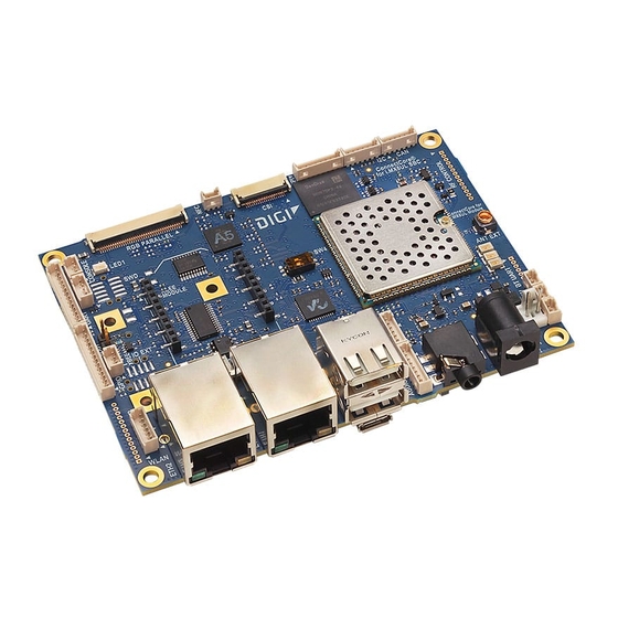
Digi ConnectCore 6UL Hardware Design Manuallines
Hide thumbs
Also See for ConnectCore 6UL:
- Hardware reference manual (135 pages) ,
- Hardware reference manual (43 pages)
Table of Contents
Advertisement
Quick Links
Advertisement
Table of Contents

Subscribe to Our Youtube Channel
Summary of Contents for Digi ConnectCore 6UL
- Page 1 ConnectCore 6UL Hardware Design Guidelines and Checklist...
- Page 2 Information in this document is subject to change without notice and does not represent a commitment on the part of Digi International. Digi provides this document “as is,” without warranty of any kind, expressed or implied, including, but not limited to, the implied warranties of fitness or merchantability for a particular purpose.
- Page 3 Feedback To provide feedback on this document, email your comments to techcomm@digi.com Include the document title and part number (ConnectCore 6UL Hardware Design Guidelines, 90002341 B) in the subject line of your email. ConnectCore 6UL Hardware Design Guidelines...
-
Page 4: Table Of Contents
Contents About this document Overview Naming and signal conventions Schematics design checklist RF guidelines RF matching network for the external antenna Regulations Bring-up guidelines Power-up Power rails Verify system boot ConnectCore 6UL Hardware Design Guidelines... -
Page 5: About This Document
This document, together with the ConnectCore 6UL System-on-Module Hardware Reference Manual, provide information key to ensuring a functional, quality design featuring the ConnectCore 6UL module. Naming and signal conventions This document is written assuming the reader has a good working knowledge of common electronics terminology. -
Page 6: Schematics Design Checklist
LDO Mosfet drain Mosfet gate 4.6V - 5.5V Without Input power line: Floating Grounded front-end 3.7V - 4.5V Note For detailed information about the input power circuitry, see the ConnectCore 6UL System-on-Module Hardware Reference Manual. ConnectCore 6UL Hardware Design Guidelines... - Page 7 MCA through Schottky diode. Note In the ConnectCore 6UL reference designs (SBC PRO and SBC Express) there's a 100 Ω series resistor between the coin-cell/supercap and VCC_LICELL signal in the circuit above. Please remove this resistor. It introduces a voltage drop in the transitory from normal operation to RTC mode operation which could cause undesirable RTC behavior.
- Page 8 LCD_DATA2 (BOOT_CFG1[2]): pull-down LCD_DATA3 (BOOT_CFG1[3]): pull-down LCD_DATA4 (BOOT_CFG1[4]): pull-up LCD_DATA5 (BOOT_CFG1[5]): pull-down LCD_DATA6 (BOOT_CFG1[6]): pull-down LCD_DATA7 (BOOT_CFG1[7]): pull-up Use 10K resistors to pull these line up or down. When pulled-high, refer these lines to 3V3_EXT. ConnectCore 6UL Hardware Design Guidelines...
- Page 9 4. Boot Boot configuration lines are latched during booting for configuring the configuration boot process of the SOM. Digi recommends you add a buffer to protect lines buffer these lines during booting. External circuitry and peripherals connected to these lines can modify the expected value when system is booting, so that the process can fail.
- Page 10 The following pads must be left unconnected to preserve this wireless functionality: K19 (WLAN_SD1_CLK) L19 (WLAN_SD1_CMD) M19 (WLAN_SD1_DATA0) L20 (WLAN_SD1_DATA1) K20 (WLAN_SD1_DATA2) M20 (WLAN_SD1_DATA3) This applies only to Wireless variants of the SOM. In non-wireless variants, the SDIO1 bus is available. ConnectCore 6UL Hardware Design Guidelines...
- Page 11 PMIC ON/OFF signal. It can be used externally for managing external circuitry but must never be driven as an input. Although this signal is not used externally, it may be helpful to leave it accessible for debugging (test points). ConnectCore 6UL Hardware Design Guidelines...
- Page 12 Schematics design checklist Naming and signal conventions Schematic: coin-cell/supercap connected to VCC_MCA through Schottky diode Schematic: boot configuration lines used on the ConnectCore 6UL SBC PRO reference design ConnectCore 6UL Hardware Design Guidelines...
-
Page 13: Rf Guidelines
Via stored tables on the firmware, a flat RF output power over frequency is provided at the U.FL connector. (That is, the same amount of power is delivered at each frequency over the band.) ConnectCore 6UL Hardware Design Guidelines... -
Page 14: Regulations
LGA pad to an external antenna. When the current calibration data based on the U.FL connector is applied to the external antenna as routed on the SBC Pro carrier board from Digi, the RF power levels are slightly lower, and also waved along frequency. If applied on another external antenna on another carrier board design, the resulting RF power levels will depend directly on the implemented matching network. -
Page 15: Bring-Up Guidelines
(or any other high- current incident) occurs. The ConnectCore 6UL SOM will not have a static power consumption higher than 120-130 mA from factory mode (except booting peaks). So, together with the expected power consumption of the carrier board, you can estimate an upper limit for the current consumption in the bring-up. - Page 16 Make sure LCD_DATA23 (BOOT_CFG4[7]) is not pulled-high. Verify that VIN_PRESENT is at high level (3.3V). Verify that POR_B signal is at high level. Note For more information, see the ConnectCore 6UL System-on-Module Hardware Reference Manual. ConnectCore 6UL Hardware Design Guidelines...


Need help?
Do you have a question about the ConnectCore 6UL and is the answer not in the manual?
Questions and answers