
Related Manuals for Digi ConnectCore 9M 2443


Summary of Contents for Digi ConnectCore 9M 2443
- Page 1 ™ ConnectCore 9M 2443 and Wi-9M 2443 Hardware Reference 90000952_B Release date: August 2009...
- Page 3 Information in this document is subject to change without notice and does not represent a commitment on the part of Digi International. Digi provides this document “as is,” without warranty of any kind, either expressed or implied, including, but not limited to, the implied warranties of fitness or merchantability for a particular purpose. Digi may make improvements and/or changes in this manual or in the product(s) and/or the program(s) described in this manual at any time.
- Page 4 ConnectCore 9M 2443 & Wi-9M 2443 Hardware Reference...
-
Page 5: Change Log
................. . Please always check the product specific section on the Digi support website for the Documentation most current revision of this document: www.digiembedded.com/support. - Page 6 C h a p t e r 1 For more information about your Digi products, or for customer service and Contact technical support, contact Digi International. information To contact Digi International by Mail Digi International 11001 Bren Road East Minnetonka, MN 55343 U.S.A...
-
Page 7: Table Of Contents
Contents ............... Change Log.................. - Page 8 3.3VDC power controller - VLIO............65 Power LEDs ................65 Coin cell for RTC ................65 Current measuring option..............65 Reset ..................65 JTAG interface ................65 I²C interface ................65 PoE connectors ................65 Peripheral application connector.............66 LCD Application Kit Connector ............66 ConnectCore 9M 2443 & Wi-9M 2443 Hardware Reference...
- Page 9 VGA interface ................66 UARTs ..................66 UART A - console ............... 66 UART B - UART / MEI ..............66 UART C - TTL interface ..............66 UART D - TTL interface ..............66 SPI interface(s) ................. 67 Camera interface................68 Switches and push-buttons ..............
- Page 10 Thermal specifications ..............131 Standard Operating Temperature Ranges ......... 131 recommendations ..............132 Power requirements ................. 133 Typical Power Requirements ............... 133 ConnectCore 9M 2443 ..............133 ConnectCore “Wi-9M 2443”............134 Mechanical specifications..............136 ConnectCore 9M 2443 & Wi-9M 2443 Hardware Reference...
- Page 11 ConnectCore 9M 2443..............136 ConnectCore Wi-9M 2443 ................138 Connector Reference Parts ..............139 Base Board Connector X1, X2 ............139 Base Board Connector X3, X4 ............139 Cable specification : U.FL/W.FL to RP-SMA FEMALE........140 Attributes ................140 Dimensions ................140 Antenna specification: 802.11a/b/g antenna..........
-
Page 12: Features And Functionality
Designed from the ground up with power budget conscious applications in mind, the ConnectCore 9M 2443 module family is an ideal system platform for mobile and battery-operated product designs with full off-the-shelf hard- and software support for all power management modes. - Page 13 Up to 33 MHz I2C-Bus Interface 1-ch Multi-Master IIC-Bus Serial, 8-bit oriented and bi-directional data transfers up to 100 Kbit/s in Standard mode or up to 400 Kbit/s in fast mode ConnectCore 9M 2443 & Wi-9M 2443 Hardware Reference...
- Page 14 SD/SDIO/MMC 1-/4-bit and block/stream, up to 25 MHzHigh-Speed (HS) MMC SD HC 1.0, SD MC 2.1, SDIO 1.0, MMC 4.2 1-/4-/8-bit modes, up to 50 MHz CE-ATA mode support CF/ATA Compact Flash 3.0 PC card mode ...
- Page 15 C h a p t e r 1 JTAG signals available on module connectors Standard module variants The ConnectCore 9M 2443 module is currently available in the standard variants below. Speed Flash SDRAM Operating temperature 533 MHz 128 MB 64 MB...
-
Page 16: Block Diagrams
B l o c k d i a g r a m s ................. . www.digiembedded.com... -
Page 17: Module
Serial EEPROM Wirel e ss SEC. Antenna Address Bus 2 b anks SDRAM l/F Data Bus SDRAM VRTC AVCC +3.3V AGND VL IO Flash Control NAND Address Bus Flash D t B ConnectCore 9M 2443 & Wi-9M 2443 Hardware Reference... -
Page 18: Detailed Module Description
................. . The ConnectCore 9M 2443 Module supports 8 configuration pins:... -
Page 19: Power Management
ADC, UART, GPIO, RTC and SPI etc. The following figure shows the clock distribution: The power management block in the S3C2443 can activate four modes: NORMAL, Power STOP, IDLE, and SLEEP. These are described below. management ConnectCore 9M 2443 & Wi-9M 2443 Hardware Reference... -
Page 20: Normal Mode
In General Clock Gating mode, the On/Off clock gating of the individual clock NORMAL mode source of each IP block is performed by controlling each corresponding clock source enable bit. The Clock Gating is applied instantly whenever the corresponding bit is changed. -
Page 21: Wake-Up Event
S3C2443X automatically recovers the previous working state after wake- up from the STOP Mode. The following table shows the states of PLLs and internal clocks after wake-ups from the power-saving modes. ConnectCore 9M 2443 & Wi-9M 2443 Hardware Reference... -
Page 22: Reset
Mode before wake-up PLL on/off after wake-up SYSCLK after wake-up SYSCLK after the lock and before the lock time time by internal logic IDLE Unchanged PLL output PLL output STOP PLL state ahead of entering STOP PLL reference clock SYSCLK ahead of entering mode (PLL ON or not) STOP mode (PLL output or not) -
Page 23: Memory
DDR-SDRAM. Features: NAND Flash memory I/F: Supports 512Bytes and 2KBytes Page. Interface: 8-bit NAND flash memory interface bus. Hardware ECC generation, detection and indication (Software correction). ConnectCore 9M 2443 & Wi-9M 2443 Hardware Reference... -
Page 24: Configuration Pins - Cpu Module
SFR I/F: Supports Little Endian Mode, Byte/half word/word access to Data and ECC Data register, and Word access to other registers. Steppingstone I/F: Supports Little/Big Endian, Byte/half word/word access. The Steppingstone 4-KB internal SRAM buffer can be used for another purpose ... -
Page 25: Chip Selects
0x0800_0000- external, RCS1# 0x083F_FFFF RCS2# RCS2# 0x1000_0000- external, RCS2# 0x103F_FFFF RCS3# RCS3# 0x1800_0000- external, RCS3# 0x183F_FFFF RCS4# RCS4# 0x2000_0000- external, RCS4# 0x203F_FFFF RCS5# RCS5# 0x2800_0000- internal, RCS5# Used for Ethernet Controller 0x283F_FFFF ConnectCore 9M 2443 & Wi-9M 2443 Hardware Reference... -
Page 26: Multiplexed Gpio Pins
M u l t i p l e x e d G P I O p i n s ................. . S3C2443X Port Configuration Port A... - Page 27 Input/Output Input GPC7 Input/Output LCD_VF[2] LCD_VF[2] GPC6 Input/Output LCD_VF[1] LCD_VF[1] GPC5 Input/Output LCD_VF[0] LCD_VF[0] GPC4 Input/Output GPC3 Input/Output VFRAME VFRAME GPC2 Input/Output VLINE VLINE GPC1 Input/Output VCLK Output GPC0 Input/Output LEND Input ConnectCore 9M 2443 & Wi-9M 2443 Hardware Reference...
- Page 28 Port D Selectable Pin Functions On module, default used as GPD15 Input/Output VD23 VD23 GPD14 Input/Output VD22 VD22 GPD13 Input/Output VD21 VD21 GPD12 Input/Output VD20 VD20 GPD11 Input/Output VD193 VD193 GPD10 Input/Output VD18 VD18 GDA9 Input/Output VD17 Input GPD8 Input/Output VD16 Input GPD7...
- Page 29 EINT0 Input Port G Selectable Pin Functions On module, default used as GPA15 Input/Output EINT23 CARD_PWREN Input GPA14 Input/Output EINT22 RESET_CF Input GPG13 Input/Output EINT21 nREG_CF Input GPG12 Input/Output EINT20 nlNPACK Input ConnectCore 9M 2443 & Wi-9M 2443 Hardware Reference...
- Page 30 Port G Selectable Pin Functions On module, default used as GPG11 Input/Output EINT19 nlREQ_CF Input GPG10 Input/Output EINT18 Input GPG9 Input/Output EINT17 Input GPG8 Input/Output EINT16 Input GPG7 Input/Output EINT15 Internal Input GPG6 Input/Output EINT14 Input GPG5 Input/Output EINT13 Input GPG4 Input/Output EINT12...
- Page 31 GPL7 Input/Output SD1_DAT7 SD1_DAT7 GPL6 Input/Output SD1_DAT6 SD1_DAT6 GPL5 Input/Output SD1_DAT5 SD1_DAT5 GPL4 Input/Output SD1_DAT4 SD1_DAT4 GPL3 Input/Output SD1_DAT3 SD1_DAT3 GPL2 Input/Output SD1_DAT2 SD1_DAT2 GPL1 Input/Output SD1_DAT1 SD1_DAT1 GPL0 Input/Output SD1_DAT0 SD1_DAT0 ConnectCore 9M 2443 & Wi-9M 2443 Hardware Reference...
-
Page 32: Interfaces
Port M Selectable Pin Functions On module, default used as GPM1 Input FRnB FRnB GPM0 Input RSMBWAIT Internal Input I n t e r f a c e s ................. . Instead of using the S3C2443-internal RTC, an external RTC (Dallas D1337) is implemented on the module to optimize the power consumption characteristics in sleep modes. - Page 33 Where DIV_VAL should be from 1 to (216-1) and SRCCLK is either PCLK or divided EPLL clock. DIV_VAL can be programmed in the S3C2443 registers the following way: DIV_VAL = UBRDIVn + (num of 1's in UDIVSLOTn)/16 ConnectCore 9M 2443 & Wi-9M 2443 Hardware Reference...
-
Page 34: Spi Interface
Where UBRDIVn is integer part of DIV_VAL - and UDIVSLOTn the floating point part of DIV_VAL. For example, if the baud rate is 115200 bps and SRCCLK is 66 MHz, UBRDIVn and UDIVSLOTn are: DIV_VAL = (66000000 / (115200 x 16)) -1 = 35.8 -1 = 34.8 * UBRDIVn = 34... -
Page 35: I2C Interface
Support Interrupt, Bulk, Isochronous Transfer One USB interface is provided at the general pins of the system connector, consisting of the data lines USBP and USBN as well as the additional signal USB_DT/PW. ConnectCore 9M 2443 & Wi-9M 2443 Hardware Reference... -
Page 36: Ethernet Interface
At the module specific pins of the system connector a second host interface (host0) is provided with the differential data lines DP0 and DN0. The ConnectCore 9M 2443 module has a 10/100Mbit Ethernet controller with Ethernet interface integrated MAC and PHY on board. -
Page 37: Wlan Interface
2.5MHz A/D converter clock. A/D converter operates with on-chip sample-and- hold function and power down mode is supported. The touch screen Interface can control/select pads (ConnectCore 9M 2443, XP, XM, YP, YM) of the Touch Screen for X, Y position conversion. The touch Screen Interface provides Touch Screen Pads control logic and ADC interface logic with interrupt generation. -
Page 38: Reset Controller
3. Auto (Sequential) X/Y Position Conversion Mode is activated as follows: Touch Screen Controller sequentially converts the X-Position or Y-Position that is touched. After touch controller writes X-measurement data to ADCDAT0 and writes Y-measurement data to ADCDAT1, the Touch Screen Interface generates Interrupt source to Interrupt Controller in Auto Position Conversion Mode. -
Page 39: Watchdog Timer
1-ch IIS-bus for audio interface with DMA-based operation Serial, 8-/16-bit per channel data transfers 128 Bytes (64-Byte + 64-Byte) FIFO for Tx/Rx Supports two IIS formats (MSB-justified or LSB-justified data format) ConnectCore 9M 2443 & Wi-9M 2443 Hardware Reference... -
Page 40: Iis Block Diagram
IIS block diagram: The IIS bus has four lines including serial data input I2SSDI, serial data output I2SSDO, IIS-Bus format left/right channel select clock I2SLRCLK, and serial bit clock I2SBCLK; the device generating I2SLRCLK and I2SBCLK is the master. Serial data is transmitted in 2's complement with the MSB first with a fixed position, whereas the position of the LSB depends on the word length. -
Page 41: Camera Interface
MSDMA supports memory data for preview path input Image effect CAMIF supports the following video standards: ITU-R BT 601 YCbCr 8-bit mode ITU-R BT 656 YCbCr 8-bit mode ConnectCore 9M 2443 & Wi-9M 2443 Hardware Reference... -
Page 42: Ac97 Controller
The figure below provides an overview of the CAMIF interface signals. All camera interface signals should have the same length. Buffers should be Schmitt-triggered. Below is the block diagram of the camera interface. The AC97 Controller Unit of the S3C2443 supports AC97 revision 2.0 features. AC97 AC97 Controller Controller communicates with AC97 Codec using an audio controller link (AC-link). - Page 43 The following shows the functional block diagram of the S3C2443 AC97 Controller. The AC97 signals form the AClink, which is a point-to-point synchronous serial interconnect that supports full-duplex data transfers. All digital audio streams and command/status information are communicated over the AC-link. ConnectCore 9M 2443 & Wi-9M 2443 Hardware Reference...
-
Page 44: Sd Host Interface
The S3C2443 Secure Digital Interface (SDI) can interface for SD memory card, SDIO SD host interface device and Multi-Media Card (MMC). Features: SD Memory Card Spec. (ver. 1.0) / MMC Spec. (2.11) compatible SDIO Card Spec (ver. 1.0) compatible ... -
Page 45: Clock Output
True-IDE mode operation. Default mode is PC card mode. The CF controller has a top level SFR with card power enable bit, output port enable bit & mode select (True-IDE or PC card) bit. ConnectCore 9M 2443 & Wi-9M 2443 Hardware Reference... -
Page 46: Pc Card Controller
The PC card controller has 2 half-word (16 bit) write buffers & 4 half-word (16bits) PC card read buffers. controller The PC card controller has 5 word-sized (32 bit) Special Function Registers. Features: 3 timing configuration registers Attribute memory ... -
Page 47: High Speed Spi
802.11a/b/g interface with data rates up to 54 Mbps. Two U.FL antenna connectors are provided on the module. For the Connect Core Wi-9M 2443, attach the antennas with the U.FL-RP-SMA FEMALE Cable to the ConnectCore 9M 2443 & Wi-9M 2443 Hardware Reference... - Page 48 primary connector [X5] and the secondary connector [X4] on the module. You must use only this cable and antennas to carry on the module. Note When disconnecting U.FL connectors, the use of U.FL plug extraction tool (Hirose P/N U.FL-LP-N-2 or U.FL-LP(V)-N-2) is strongly recommended to avoid damage to the U.FL connectors on the ConnectCore Wi-9M 2443 module.
-
Page 49: Lcd Controller Display Features
Maximum virtual screen size in 64K color mode: 2048 x 1024, and others 2 overlay windows for TFT The LCD controller has a dedicated DMA that supports fetching image data from Common features ConnectCore 9M 2443 & Wi-9M 2443 Hardware Reference... -
Page 50: Module Pinout
a video buffer located in system memory. Its features include: Dedicated interrupt functions (INT_FrSyn and INT_FiCnt) System memory used as display memory Multiple Virtual Display Screen (supports hardware horizontal/vertical scrolling) Programmable timing control for different display panels ... - Page 51 CAMDATA1 CAMDATA1 Pixel data driven by the camera processor GPJ1 X1-31 CAMDATA2 CAMDATA2 Pixel data driven by the camera processor GPJ2 X1-32 CAMDATA3 CAMDATA3 Pixel data driven by the camera processor GPJ3 ConnectCore 9M 2443 & Wi-9M 2443 Hardware Reference...
- Page 52 Signal Type Signal name Description X1-33 CAMDATA4 CAMDATA4 Pixel data driven by the camera processor GPJ4 X1-34 CAMDATA5 CAMDATA5 Pixel data driven by the camera processor GPJ5 X1-35 CAMDATA6 CAMDATA6 Pixel data driven by the camera processor GPJ6 X1-36 CAMDATA7 CAMDATA7 Pixel data driven by the camera processor GPJ7...
- Page 53 LCD/TFT Interface GPC1 X1-67 LEND LEND LCD/TFT Interface GPC0 X1-68 LCD_LPCOE LCDVF0 LCD/TFT Interface GPC5 X1-69 LCD_LPCREV LCDVF1 LCD/TFT Interface GPC6 X1-70 LCD_LPCREVB LCDVF2 LCD/TFT Interface GPC7 X1-71 TOUT0 TOUT0 Timer out GPB0 ConnectCore 9M 2443 & Wi-9M 2443 Hardware Reference...
- Page 54 Signal Type Signal name Description X1-72 TOUT1 TOUT1 Timer out GPB1 X1-73 WLAN_DISABLE# Not connected; reserved for CCW9M X1-74 WLAN_LED# Not connected; reserved for CCW9M X1-75 SDCLK SD0_CLK SD-interface GPE5 AC_BIT_CLK X1-76 SDCMD SD0_CMD SD-interface GPE6 AC_SDI X1-77 SDDATA0 SD0_DAT[0] SD-interface GPE7 AC_SDO...
- Page 55 USB data host1, device X1-115 USBN USBN USB data host1, device X1-116 VRTC VRTC Power for RTC X1-117 X1-118 +3.3V +3.3V +3.3V for peripherals X1-119 VLIO VLIO Power from Li-Ion battery for core ConnectCore 9M 2443 & Wi-9M 2443 Hardware Reference...
-
Page 56: System Connector X2
Signal Type Signal name Description X1-120 +3.3V +3.3V +3.3V for peripherals System connector Signal Type Signal name Description X2-1 USBP0 USBP0 USB data host0 X2-2 X2-3 USBN0 USBN0 USB data host 0 X2-4 RADDR0 RADDR0 GPA0 X2-5 RADDR1 RADDR1 Address line X2-6 RADDR2 RADDR2... - Page 57 A/D converter X2-44 AIN1 AIN1 A/D converter X2-45 AIN2 AIN2 A/D converter X2-46 AIN3 AIN3 A/D converter X2-47 AIN6/YM AIN6/YM A/D converter or touch interface X2-48 AIN7/YP AIN7/YP A/D converter or touch interface ConnectCore 9M 2443 & Wi-9M 2443 Hardware Reference...
- Page 58 Signal Type Signal name Description X2-49 AIN8/XM AIN8/XM A/D converter or touch interface X2-50 AIN9/XP AIN9/XP A/D converter or touch interface X2-51 AVCC AVCC Analog VCC X2-52 AGND AGND Analog GND X2-53 Reserved for CCW9M CPLD_TDI X2-54 Reserved for CCW9M CPLD_TCK X2-55 Reserved for CCW9M CPLD_TMS X2-56...
- Page 59 Data Bus X2-90 RDATA9 RDATA9 Data Bus X2-91 RDATA10 RDATA10 Data Bus X2-92 RDATA11 RDATA11 Data Bus X2-93 RDATA12 RDATA12 Data Bus X2-94 RDATA13 RDATA13 Data Bus X2-95 RDATA14 RDATA14 Data Bus ConnectCore 9M 2443 & Wi-9M 2443 Hardware Reference...
- Page 60 Signal Type Signal name Description X2-96 RDATA15 RDATA15 Data Bus X2-97 SD1_DAT0 SD1_DAT0 SD card interface 1 GPL0 X2-98 SD1_DAT1 SD1_DAT1 SD card interface 1 GPL1 X2-99 SD1_DAT2 SD1_DAT2 SD card interface 1 GPL2 X2-100 SD1_DAT3 SD1_DAT3 SD card interface 1 GPL3 X2-101 SD1_DAT4...
-
Page 61: Configuration Pins - Cpu
= don't care OM0 is fixed to GND for setting XTAL. OM4 is fixed to GND for setting NAND. OM1-3 are depending of the FLASH type. No pins are available on the module connectors. ConnectCore 9M 2443 & Wi-9M 2443 Hardware Reference... -
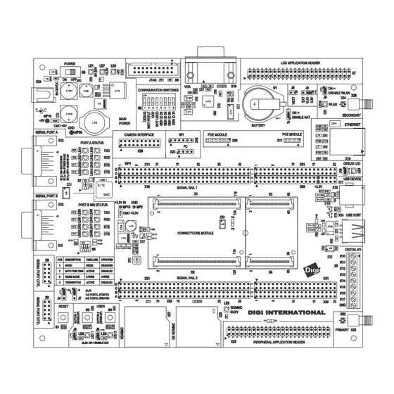
Page 62: What's On The Development Board
About the Development Board he ConnectCore 9M 2443 Development Board supports the ConnectCore 9M 2443 and ConnectCore Wi-9M 2443 module. This chapter describes the different components of the development board, which provides the following main features: RJ-45 Ethernet Connector What’s on the ... -
Page 63: The Development Board
C h a p t e r 2 The development board ConnectCore 9M 2443 & Wi-9M 2443 Hardware Reference... -
Page 64: User Interface
................. . The ConnectCore 9M 2443 development board implements two user buttons and two user LEDs in addition to those provided on the module. -
Page 65: Vdc Power Controller - Vlio
3.3VDC power supply. – All power LEDs are red. A 3.0V coin cell should be used on the ConnectCore 9M 2443 development Coin cell for RTC board for powering the RTC unit on the module. Measuring the current on the development board allows evaluation of power Current ... -
Page 66: Peripheral Application Connector
UART B line drivers can be disabled if required. The ConnectCore 9M 2443 UART C signals provide access to TXD, RXD and CTS#, UART C - TTL RTS# (if UART D is not used, else TXD, RXD only). -
Page 67: Spi Interface(S)
C h a p t e r 2 The ConnectCore 9M 2443 development board provides access to ConnectCore SPI interface(s) 9M 2443 module's SPI interfaces SPI0 and SPI1. HS SPI0 signals are available on the dedicated SPI 6-pin header. -
Page 68: Camera Interface
YCbCr 4:2:0 or 4:2:2. Camera interface, The Digi Multimedia Application Kit (Digi P/N CC-ACC-MMK-2443) provides a camera sensor reference design. Please contact your distributor or Digi sales office for details. www.ConnectCore 9M 2443 & Wi-9M 2443 Hardware Reference.com... -
Page 69: Switches And Push-Buttons
9V-30V input power supply and 12V coming out of the PoE module. However, if a power plug is connected to the DC power jack, the PoE module is disabled. User pushbuttons, S3 and S5. ConnectCore 9M 2443 & Wi-9M 2443 Hardware Reference... -
Page 70: Legend For Multi-Pin Switches
Auto Power Down feature (S6.2 = ON). Be sure that no cable is connected to connector X3. S6.3 On = 2 wire interface (RS422/RS485) Off = 4 wire interface (RS422) www.ConnectCore 9M 2443 & Wi-9M 2443 Hardware Reference.com... -
Page 71: Test Points
GND, MP13 / Numbers and description Test Label Source / comment point MP10 DC/DC regulator (U15) with 9-30VDC input MP30 Common ground MP13 +3.3V DC/DC regulator (U23) with 5VDC input Common ground ConnectCore 9M 2443 & Wi-9M 2443 Hardware Reference... -
Page 72: Factory Default Interface Configuration For Development Board
C user-driven I/Os Enabled EIA-232 Serial Port A Enabled EIA-485 Serial Port A Disabled EIA-232 Serial Port B Enabled TTL Serial Port C Disabled TTL Serial Port D Disabled SPI Serial Port B Disabled www.ConnectCore 9M 2443 & Wi-9M 2443 Hardware Reference.com... -
Page 73: Leds
Power LEDs, switched. LE1, LE4, and LE1 ON indicates +9VDC / +30VDC power is present LE4 ON indicates +5VDC power is present LE7 ON indicates +3.3VDC power is present ConnectCore 9M 2443 & Wi-9M 2443 Hardware Reference... -
Page 74: User Leds, Le5 And Le6
Serial port A (R232), X27 Serial port B, (MEI), X16 Serial port C, TTL, X19 Serial port D, TTL, X22 Green means corresponding signal is high Red means corresponding signal is low www.ConnectCore 9M 2443 & Wi-9M 2443 Hardware Reference.com... -
Page 75: Status Leds Serial Port A
LE41 LE40 TXD0/GPH0 Status LEDs Serial port B LED reference Function GREEN LE63 LE48 CTS1#/GPH10 LE62 LE47 RTS1#/GPH11 LE61 LE46 RXD1/GPH3 LE60 LE45 TXD01GPH2 Debug, LE3 Signal name GPIO used DEBUG_LED GPB2/TOUT2 ConnectCore 9M 2443 & Wi-9M 2443 Hardware Reference... -
Page 76: Battery And Battery Holder
The development board provides a battery to back up the module integrated RTC while the main power is disconnected. The Jumper J1 controls whatever battery power is available. For more information see the section, “Jumpers” on page 103 of this document. www.ConnectCore 9M 2443 & Wi-9M 2443 Hardware Reference.com... -
Page 77: Serial Uart Ports
The serial port A interface corresponds to S3C2443 UART 0. The line driver is enabled or disabled using S7.2. Refer to page 68 for information about switch settings. ConnectCore 9M 2443 & Wi-9M 2443 Hardware Reference... - Page 78 Function Defaults to GPH1 GPH0 RTS# GPH9 CTS# GPH8 By default, serial A signals are configured to their respective GPIO signals. It is the responsibility of the driver to configure them properly. www.ConnectCore 9M 2443 & Wi-9M 2443 Hardware Reference.com...
-
Page 79: Serial Port B, Mei Interface, X16
By default serial B signals are configured to their respective GPIO signals. It is the responsibility of the driver to configure them properly. Serial port C, TTL interface, Function Defaults to RXD2 GPH5 RTS2#/TXD3 GPH6 TXD2 GPH4 CTS2#/RXD3 GPH7 +3.3V ConnectCore 9M 2443 & Wi-9M 2443 Hardware Reference... -
Page 80: Serial Port D, Ttl Interface, X22
Serial port D, TTL interface, Function Defaults to CTS2#/RXD3 GPH7 RTS2#/TXD3 GPH6 +3.3V www.ConnectCore 9M 2443 & Wi-9M 2443 Hardware Reference.com... -
Page 81: I2C Interface
The table below provides the pinout of the I2C header. I2C connector, Function Comment I2C_SDA GPE15 +3.3V I2C_SCL GPE14 See page 91 for information about I/O expander I2C device on the development board. ConnectCore 9M 2443 & Wi-9M 2443 Hardware Reference... -
Page 82: Spi Interface
................. . SPI header, X8 www.ConnectCore 9M 2443 & Wi-9M 2443 Hardware Reference.com... -
Page 83: X8-Spi Connector
GPE12 or High speed SPI Master Out Slave In SPI_MISO0 GPE12 or High speed SPI Master In Slave Out SPI_CLK0 GPE12 or High speed SPI clock SS0# GPE13 or High speed SPI Chip Select ConnectCore 9M 2443 & Wi-9M 2443 Hardware Reference... -
Page 84: Current Measurement Option
R39 The Current Measurement Option uses 0.025R ohm series resistors to measure the Measurement current. The ConnectCore 9M 2443 Development board can measure: options the +5V current used by the development board and module (through R80), ... -
Page 85: How The Cmo Works
(CMO) resistor. The value of the resistor is 0.025R ± 1%. Calculate the current using this equation: I = U/R where I = current in Ampere U = measured voltage in Volt R = 0.025 Ohm ConnectCore 9M 2443 & Wi-9M 2443 Hardware Reference... -
Page 86: Poe Module Connectors - Ieee802.3Af
X26, output connector: Provides the output power supply from the PoE module. X17, input connector: Provides access to the signals coming from the Ethernet interface. PoE header, X26 PoE header, X17 www.ConnectCore 9M 2443 & Wi-9M 2443 Hardware Reference.com... -
Page 87: The Poe Module
(power out), X26 Function +12V +12V POE_GND POE_GND The development board provides access to POE_GND allowing it to be turned off POE_GND when power is provided through Power Jack X26.9 and X26.5. ConnectCore 9M 2443 & Wi-9M 2443 Hardware Reference... -
Page 88: Vga Connector
................. . VGA connector, X18 The VGA connector is a 15-pin female connector, labeled X18. VGA connector, www.ConnectCore 9M 2443 & Wi-9M 2443 Hardware Reference.com... - Page 89 NC (Monitor ID2) Monitor ID2 is not implemented on the development board VGA_GND (RED_RETURN) VGA_GND (GREEN_RETURN) VGA_GND (BLUE_RETURN) GND (SYNC_RETURN) NC (Monitor ID0) Monitor ID0 is not implemented on the development board HSYNC VSYNC ConnectCore 9M 2443 & Wi-9M 2443 Hardware Reference...
-
Page 90: Usb Connectors
X15 This standard type A receptacle provides access to the module USB host interface. USB host The module supports USB 2.0 device connectivity using low and full speed data connector, X14 rates. www.ConnectCore 9M 2443 & Wi-9M 2443 Hardware Reference.com... -
Page 91: Digital I/O
The I/O expander is a Philips PCA9554D at I2C address 0x20 (bits A7..A1), or 0x40/0x41 if expressed in 8-bit format including the R/W bit at the end (bits A7..A1 + R/W bit)." The pins are allocated as shown below: Function Function IO_0 IO_5 ConnectCore 9M 2443 & Wi-9M 2443 Hardware Reference... -
Page 92: Jtag Interface
................. . JTAG connector, X13 www.ConnectCore 9M 2443 & Wi-9M 2443 Hardware Reference.com... -
Page 93: Standard Jtag Arm Connector, X13
C h a p t e r 2 The standard JTAG ARM connector is a 20-pin header and can be used to connect Standard JTAG development tools such as Digi JTAG Link, ARM Multi-ICE, Abatron BDI2000 and ARM connector, others. -
Page 94: Peripheral (Extension) Headers
X5, LCD application header. Provides access to the LCD signals and SPI signals for touch controller purposes. Use with a Digi-provided application kit or attach your own application board. X33, Peripheral application header. Provides access to an 8/16 bit data bus, 8- ... -
Page 95: Lcd Application Header, X5
VD23 VD10 VD11 VD12 VD13 VD14 VD15 VD21 Reserved (LCD_D18) Reserved (LCD_D19) Reserved (LCD_D20) Reserved (LCD_D21) I2C_SDA I2C-SCL VCLK VLINE VFRAME EINT13 LCD_PWREN# +3.3V TSXP TSYP TSXM TSYM +3.3V +3.3V +3.3V +3.3V ConnectCore 9M 2443 & Wi-9M 2443 Hardware Reference... -
Page 96: Peripheral Application Header, X3
Peripheral application Signal Signal header, X3 G ND 8 bit / 16 bit +3.3V selects 8-bit data bus +3.3V +3.3V CS1# I2C_SDA I2C_SCL EINT13 +3.3V +3.3V USBPO USBNO No comment www.ConnectCore 9M 2443 & Wi-9M 2443 Hardware Reference.com... -
Page 97: Module Connectors And Signal Rails
The development board also provides two 4x20 pin test connectors for extended footprint modules: X30 and X31 correspond to extended module connector X3. X40 and X41 correspond to extended module connector X4. ConnectCore 9M 2443 & Wi-9M 2443 Hardware Reference... -
Page 98: X10 Pinout
VD12 VD15 EINT14 VD19 VD20 VD23 LCD_PWREN# VLINE VCLK LCDVF1 LCDVF2 WLAN_DISABLE# WACT_LED# SDDATA0 SDDATA1 SDDATA3 USERKEY1/EINT0 SS1# SPIMISO1 SD_WP# SD_CD# WAIT# CS3# CS4# DQM2 DQM3 SPIMOS10 SPICLK0 USB_DT/PW USBP +3.3V +3.3V www.ConnectCore 9M 2443 & Wi-9M 2443 Hardware Reference.com... -
Page 99: X11 Pinout
VD18 VD21 VD22 VFRAME# LEND LCDVF0 TOUT0 TOUT1 SDCLK SDCMD SDDATA2 X1.83 DEBUG_LED USERLED1/SPIMOSI1 USERLED2/SPICLK1 X1.91 CS1# CS2# PWREN BATT_FLT# DQM0 DQM1 SS0# SPIMISO0 I2C_SCL I2C_SDA USBN VRTC VLIO VLIO +3.3V +3.3V ConnectCore 9M 2443 & Wi-9M 2443 Hardware Reference... -
Page 100: X20 Pinout
AIN4 AIN5 AIN2 AIN3 AIN8/XM AIN9/XP XBREQ# XBACK# I2SSDO/ACDO I2SSDI/ACDI I2SLRCK/AC_RESET#GPEO LEDSPD OE_CF# WE_CF# REG_CF# SDDATA1 SD1_DAT0 SD1_DAT1 SD1_DAT4 SD1_DAT5 SD1_CMD SD1_CLK SD1_LED# USERKEY2/EINT6 X2.113 X2.114 X1.117 X2.118 VLIO VRTC +3.3V +3.3V www.ConnectCore 9M 2443 & Wi-9M 2443 Hardware Reference.com... -
Page 101: X21 Pinout
USBN0 TXD1 CTS1# XDREQ0# XDACK1# AIN0 AIN1 AIN6YM AIN7/YP AVCC AGND USBHOPEN I2SCDCLK/AC_BIT_CLK I2SSCLK/AC_SYNC/GPE1 LEDLNK FULLED# IREQ_CF# INPACK_CF# CF_PWEN SDI_DAT2 SD1_DAT3 SD1_DAT6 SD1_DAT7 SD1_WP# SD1_CD# EINT13 X2.112 X2.115 CLKOUT1 BCLKOUT0 +3.3V +3.3V ConnectCore 9M 2443 & Wi-9M 2443 Hardware Reference... -
Page 102: Power Connector
Power connector The power connector is a barrel connector with a 9-30VDC operating range. The power jack is labeled X24 on the development board. The figure below represents the power jack polarity. www.ConnectCore 9M 2443 & Wi-9M 2443 Hardware Reference.com... -
Page 103: Jumpers
External VLIO VLIO power supply J5 source J3 WLAN disable J9 Battery Jumper Debug LED Jumper J10 Port C select J4 Port D select User LED1 Jumper J6 User LED2 Jumper J8 ConnectCore 9M 2443 & Wi-9M 2443 Hardware Reference... -
Page 104: Jumpers
Disables the WLAN interface on the Closed = WLAN disabled module (if present) Open = WLAN enabled Debug LED Debug LED enable / disable Closed = Debug LED enabled Open = Debug LED disabled www.ConnectCore 9M 2443 & Wi-9M 2443 Hardware Reference.com... -
Page 105: Ethernet Interface
The Ethernet connector is an 8-wire RJ-45 jack, labeled X19, on the development board. The connector has eight interface pins, as well as two integrated LEDs that provide link status and network activity information. ConnectCore 9M 2443 & Wi-9M 2443 Hardware Reference... -
Page 106: Pin Allocation, X7
Description Yellow Network activity (speed): -Flash indicates network traffic detected -Off indicates no network traffic detected Green Network link: -On indicates an active network link -Off indicates no network link is present www.ConnectCore 9M 2443 & Wi-9M 2443 Hardware Reference.com... - Page 107 Horizontal sync driven by camera procesor CAMVSUNC Frame sync driven by camera processor I2C_SCL I2C bus for initialization I2C_SDA I2C bus for initialization XDACK0# GPIO (not used) CAMRESET Reset to the camera processor Power (not used) ConnectCore 9M 2443 & Wi-9M 2443 Hardware Reference...
-
Page 108: Wlan Interface
................. . For the ConnectCore Wi-9M 2443, attach the antenna to the primary connector [X23] and the secondary connector [X34] on the development board. See figure below. www.ConnectCore 9M 2443 & Wi-9M 2443 Hardware Reference.com... -
Page 109: Interfaces Without Special Connectors
X20 A13 AIN9/XP X210 B13 CF signals Signal name Signal rail CF_OE# X20 A19 CF_WE# X20 B19 CF_IREQ# X21 C19 CF_INPACK# X21 D19 CF_PWEN# X21 C20 CF_REG# X20 A20 CF_RESET# X20 B20 ConnectCore 9M 2443 & Wi-9M 2443 Hardware Reference... -
Page 110: I2S/Ac97 Signals
SPI1 signal Signal name Signal rail SPIMOSI1 X21 D28 SPIMISO1 X20 B28 SPICLK1 X21 C28 SS1# X21 C29 An expansion board is available for the ADC, CF, I2S/AC97, and SPI1 signals above. www.ConnectCore 9M 2443 & Wi-9M 2443 Hardware Reference.com... -
Page 111: Module And Test Connectors
................. . The ConnectCore 9M 2443 module plugs into the module connectors X1 and X2 on X1 pinout the development board.AI = Analog Input... - Page 112 Connected via RS232 driver to RxD0 COMA, X27 GPH1 RTS0# RTS0# Configured to Connected via RS232 driver to RTS0# COMA, X27 GPH9 CTS0# CTS0# Configured to Connected via RS232 driver to CTS0# COMA, X27 GPH8 www.ConnectCore 9M 2443 & Wi-9M 2443 Hardware Reference.com...
- Page 113 Pixel data driven Connected to X28 by the camera GPJ2 processor, input with pull-up enabled CAMDATA3 CAMDATA3 Pixel data driven Connected to X28 by the camera GPJ3 processor, input with pull-up enabled ConnectCore 9M 2443 & Wi-9M 2443 Hardware Reference...
- Page 114 Connected to LCD output, pull-up Application Header X5 GPC13 enabled Configured as Connected to LCD output, pull-up Application Header X5 GPC14 enabled Configured as Connected to LCD output, pull-up Application Header X5 GPC15 enabled www.ConnectCore 9M 2443 & Wi-9M 2443 Hardware Reference.com...
- Page 115 Application Header X5 GPD11 enabled VD20 VD20 Configured as Connected to LCD output, pull-up Application Header X5 GPD12 enabled VD21 VD21 Configured as Connected to LCD output, pull-up Application Header X5 GPD13 enabled ConnectCore 9M 2443 & Wi-9M 2443 Hardware Reference...
- Page 116 X11;C18 GPB0 disabled TOUT1 TOUT1 Configured as Not used, connected to output, pull-up X11;D18 GPB1 disabled WLAN_DISABL Reserved for Connected to Jumper J9 CCW9M2443 (set=disabled) WACT_LED# Reserved for Connected to LE10(low=on) CCW9M2443 www.ConnectCore 9M 2443 & Wi-9M 2443 Hardware Reference.com...
- Page 117 Connected toUSERLED1 output, pull-up SPIMOSI1 enabled GPL11 USERLED2 Configured as Connected to USERLED2 output, pull-up SPICLK1 enabled GPL10 SD_WP# EINT17 Configured as Connected to SD connector input, pull-up GPG9 disabled Write protect ConnectCore 9M 2443 & Wi-9M 2443 Hardware Reference...
- Page 118 Not used on CCW9M2443 module for wireless LAN. PWREN 1.3V power Connected to CPLD control signal 0 = Power for unneeded parts is switched off Must be left unconnected if not used www.ConnectCore 9M 2443 & Wi-9M 2443 Hardware Reference.com...
- Page 119 USB_DT/PW Default GPG0 Optional output to switch on input. 1k5 pull-up resistor for USB GPG0 device (CC9M2440 EINT8 compatibility) USBP DP_UDEV USB device USB device data line + connected to X12 ConnectCore 9M 2443 & Wi-9M 2443 Hardware Reference...
- Page 120 Can be left floating, if RTC backup is not needed. +3.3V +3.3V VLIO Mobile: Power Delivers either power from Li- from Li-Ion Ion battery or 3.3V Battery Non-Mobile: connected to 3.3V +3.3V +3.3V www.ConnectCore 9M 2443 & Wi-9M 2443 Hardware Reference.com...
-
Page 121: X2 Pinout
Used as address of Connected to X33 Peripheral WM500ABG. Application header RADDR8 Connected to X33 Peripheral Application header RADDR9 Connected to X33 Peripheral Application header RADDR10 Not used RADDR11 Not used RADDR12 Not used ConnectCore 9M 2443 & Wi-9M 2443 Hardware Reference... - Page 122 Connected to PortB MEI GPH10 RTS1# RTS1# Port RTS Connected to PortB MEI GPH11 Not connected XDREQ0# Configured as input, pull-up Not used enabled GPB10 XDREQ1# Configured as input, pull-up Not used enabled GPB8 www.ConnectCore 9M 2443 & Wi-9M 2443 Hardware Reference.com...
- Page 123 Used for touch screen Connected to LCD. TSYP/JSCC9M2443 Application connector X5. AIN8/XM Used for touch screen Connected to LCD. TSXM/JSCC9M2443 Application connector X5. AIN9/XP Used for touch screen Connected to LCD. TSXP/JSCC9M2443 Application connector X5. ConnectCore 9M 2443 & Wi-9M 2443 Hardware Reference...
- Page 124 I2SSC I2SSCLK I2S-interface, pull-up disabled Not used GPE1 AC_SYNC I2SLR GPE0 I2S-interface, pull-up disabled Not used AC_RESET# TPIN Ethernet 0 output- Connected to RJ45 with integrated magnetics 100R differential termination on module www.ConnectCore 9M 2443 & Wi-9M 2443 Hardware Reference.com...
- Page 125 GPG15 EINT23 Compact FLASH signal Not used. CF_PWREN GPG15 RDATA0 Data Bus Connected to X33 Peripheral Application Header RDATA1 Connected to X33 Peripheral Application Header RDATA2 Connected to X33 Peripheral Application Header ConnectCore 9M 2443 & Wi-9M 2443 Hardware Reference...
- Page 126 GPL3 SD1_D SD1_DAT4 HS-SD data Connected to X25 SD/MMC connector GPL4 SD1_D SD1_DAT5 HS-SD data Connected to X25 SD/MMC connector GPL5 SD1_D SD1_DAT6 HS-SD data Connected to X25 SD/MMC connector GPL6 www.ConnectCore 9M 2443 & Wi-9M 2443 Hardware Reference.com...
- Page 127 Not connected Not connected CLKO CLKOUT1 Clock output, unbuffered Not used CLKOUT1 signal, 22R series GPH10 resistor on module Not connected Not connected CLKO BCLKOUT0 Clock output, buffered Not used CLKOUT0 signal GPH9 ConnectCore 9M 2443 & Wi-9M 2443 Hardware Reference...
-
Page 128: Network Interface
Appendix A: Specifications his appendix provides specifications for the modules and the development board. N e t w o r k i n t e r f a c e ................. . Standard: IEEE 802.3 ... - Page 129 -86 dBm @ 2 Mbps – – -84 dBm @ 5.5 Mbps – -80 dBm @ 11 Mbps Available Transmit Power Settings (Maximum power setting will vary according to individual country regulations.) ConnectCore 9M 2443 & Wi-9M 2443 Hardware Reference...
-
Page 130: Environmental Specifications
802.11b/g: 15 dBm (~31 mW) @ 1, 2, 5.5, and 11 Mbps – – 12 dBm (~15 mW) @ 6,12, 18, 24, 36, 48, and 54 Mbps Available Transmit Power Settings (Maximum power setting will vary according to individual country regulations.) 802.11a: –... -
Page 131: Thermal Specifications
................. . The table below shows the specific standard operating temperature ranges for the entire ConnectCore 9M 2443 embedded core module family. Standard... -
Page 132: Recommendations
The maximum component case temperature must remain below the maximum, measured at the devices shown in the figure below. Measure Tcase of U22 Measure Tcase of U3 When attaching thermocouples, please follow the guidelines listed below: Carefully remove any labels or other foreign material from the component. ... -
Page 133: Power Requirements
Power Power U-Boot 142mA 168mA 1023mW 147mA 168mA 1040mW Windows CE 112mA 167mA 921mW 129mA 165mA 971mW Ethernet Reset 120mA 70mA 627mW 129mA 70mA 657mW Suspend 26mA 27mA 175mW 30mA 26mA 185mW ConnectCore 9M 2443 & Wi-9M 2443 Hardware Reference... - Page 134 Note: The higher VLIO current of 400 MHz variant due to speed grade specific S3C2443 PLL voltage requirements. U-Boot – U-Boot idle; waiting for serial input – 100 Mbit Ethernet connection idle – All peripherals provided with clock signals, but not initialized Windows Embedded CE ...
- Page 135 Wireless Receive – Wireless interface initialized, receive only – Windows Embedded CE idle – 100 Mbit Ethernet connection idle – All peripherals except camera and sound provided with clock signals and initialized ConnectCore 9M 2443 & Wi-9M 2443 Hardware Reference...
-
Page 136: Mechanical Specifications
................. . Below are the mechanical dimensions of the ConnectCore 9M 2443 Module. - Page 137 (minimum 5mm) and its value needs to be chosen in such a way that ensures: 2.5mm + 4.1mm + h ≤ 13.7mm. See “Connector Reference Parts” table below for further details. ConnectCore 9M 2443 & Wi-9M 2443 Hardware Reference...
-
Page 138: Connectcore Wi-9M 2443
The size of the extended module is defined as 92 x 44mm. Three holes for M2 ConnectCore screws are provided to enable secure mounting of the module on the base board. Wi-9M 2443 www.digiembedded.com... -
Page 139: Connector Reference Parts
Base Board Connector X3, X4 PCB Distance Positions Vendor Manufacturer Part Number 5 mm Tyco 5177984-5 61083-061009 6 mm Tyco 5179029-5 61083-062009 7 mm Tyco 5179030-5 61083-063009 8 mm Tyco 5179031-5 61083-064009 ConnectCore 9M 2443 & Wi-9M 2443 Hardware Reference... -
Page 140: Cable Specification : U.fl/W.fl To Rp-Sma Female
C a b l e s p e c i f i c a t i o n : U . F L / W . F L t o R P - S M A F E M A L E . -
Page 141: Antenna Specification: 802.11A/B/G Antenna
See measurements in the drawing after the table. Maximum Power level Operationg temperature Storage temperature Part number ANT-DB1-RAF-RPS Note: Dimensions are provided for reference purposes only. The actual antenna Dimensions might vary. ConnectCore 9M 2443 & Wi-9M 2443 Hardware Reference... -
Page 142: Antenna Specification: 802.11B/G Antenna
A n t e n n a S p e c i f i c a t i o n : 8 0 2 . 1 1 b / g a n t e n n a ................. . Attributes Attribute Property... -
Page 143: Polar Plots
The red solid line represents the horizontal plan and the green dotted line represents the vertical plane. You can see in the illustration that at 90 degrees, the signal strength is 0 (as expected). ConnectCore 9M 2443 & Wi-9M 2443 Hardware Reference... -
Page 144: Safety Statements
S a f e t y s t a t e m e n t s ................. . To avoid contact with electrical current: Never install electrical wiring during an electrical storm. -
Page 145: Fcc Part 15 Class B
................. . Radio Frequency Interface (RFI) (FCC 15.105) The ConnectCore 9M 2443 module has been tested and found to comply with the limits for Class B digital devices pursuant to Part 15 Subpart B, of the FCC rules. - Page 146 20cm separation, and end users be also be advised ot the requirement. Modifications (FCC 15.21) Changes or modifications to this equipment not expressly approved by Digi may void the user’s authority to operate this equipment. Industry Canada...
- Page 147 OEM installers and users are cautioned to take note that high-power radars are allocated as primary users (meaning they have priority) of the bands 5250-5330 MHz and 5650-5850 MHz and these radars could cause interference and /or damage to devices operating in these frequency bands. Indoor/Outdoor When the ConnectCore W9M2443 module is installed in devices that can be used outdoors, the channels in the band 5150-5250 MHz must be disabled to comply with...
- Page 148 The product listed above has been tested at an External Test Laboratory certified per FCC rules and has been found to meet the FCC, Part 15, Class B, Emission Limits. Documentation is on file and available from the Digi International Homologation Department.
- Page 149 International EMC Standards The ConnectCore 9M 2443 meets the following standards: Standards ConnectCore 9M 2443 Emissions FCC Part 15 Subpart B IS-003 Immunity EN 55022 EN 55024 Safety UL 60950-1 CSA C22.2, No. 60950-1 EN60950-1 www.digiembedded.com...
Need help?
Do you have a question about the ConnectCore 9M 2443 and is the answer not in the manual?
Questions and answers