Table of Contents
Advertisement
Quick Links
Advertisement
Table of Contents

Related Manuals for Digi XBee-PRO 900HP DigiMesh Kit


Summary of Contents for Digi XBee-PRO 900HP DigiMesh Kit
- Page 1 XBee-PRO 900HP DigiMesh Kit Radio Frequency (RF) Module User Guide...
- Page 2 Information in this document is subject to change without notice and does not represent a commitment on the part of Digi International. Digi provides this document “as is,” without warranty of any kind, expressed or implied, including, but not limited to, the implied warranties of fitness or merchantability for a particular purpose.
-
Page 3: Table Of Contents
Contents XBee-PRO 900HP DigiMesh Kit User Guide Kit contents Introduction to XBee modules DigiMesh networks Synchronous sleeping network Mesh networking Getting Started with your DigiMesh kit Plug in the XBee module How to unplug an XBee module Download and install XCTU... - Page 4 Step 3: Configure the XBee modules Step 4: Set up the components Step 5: Send messages via a bridge node Wireless data transmission Transmission methods Broadcast transmission Unicast transmission Lab: Transmit data wirelessly Step 1: Requirements XBee-PRO 900HP DigiMesh Kit User Guide...
- Page 5 Step 7: Set the port name and launch the application Step 8: Section summary of receiving digital data Step 9: Do more with receiving digital data Lab: Receive analog data Step 1: Requirements Step 2: Connect the components Step 3: Configure the XBee modules XBee-PRO 900HP DigiMesh Kit User Guide...
- Page 6 Is RSSI the best indication of link quality? Range test Example: perform a range test Step 1: Requirements Step 2: Connect the components Step 3: Configure the XBee modules Perform a range test Step 5: Section summary of signal strength XBee-PRO 900HP DigiMesh Kit User Guide...
- Page 7 Radio firmware Firmware identification Update radio firmware Update your device's firmware Download new firmware Troubleshooting for XBee-PRO 900HP DigiMesh Kit kit General Cannot find the serial port for the module Can't identify XBee modules Error: Port is already in use...
- Page 8 Industrial solutions Related products XBee-PRO 900HP DigiMesh Kit User Guide...
- Page 9 XBee-PRO 900HP DigiMesh Kit User Guide Digi’s XBee-PRO 900HP DigiMesh Kit is a great way to learn how to use XBee RF modules for device connectivity and mesh networking. This kit lets anyone get started in the world of DigiMesh. Whether you're a hardware or software engineer, corporate technologist, educator, or student, you can quickly create wireless mesh networks.
- Page 10 XBee-PRO 900HP DigiMesh Kit User Guide Each section of this guide explains a basic topic related to XBees and DigiMesh with step-by-step examples that put into practice the concepts you have learned. The topics are arranged according to their complexity, from the most basic to the more powerful features.
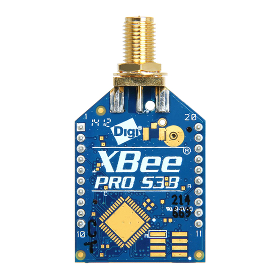
- Page 11 Kit contents Your XBee-PRO 900HP DigiMesh Kit contains the following components: Qty. Part XBee Grove Development Boards XBee-PRO 900HP RF modules Micro USB cables XBee-PRO 900HP DigiMesh Kit User Guide...
- Page 12 (PCB), although it is common for the carrier board to contain a female socket. Surface-mount technology (SMT) XBees include 37 pads. They are placed directly on the PCB, which means they do not require holes or sockets for mounting the component. XBee-PRO 900HP DigiMesh Kit User Guide...
-
Page 13: Introduction To Xbee Modules
Using XBee technology in industrial solutions. For example, XBee devices are used as sensors to monitor industrial tanks for liquid levels, temperature, and pressure, and to monitor and control complex machines such as wind turbines. XBee-PRO 900HP DigiMesh Kit User Guide... -
Page 14: Digimesh Networks
Selective acknowledgments: Only the destination node will reply to route requests. Reliable: Acknowledgments confirm successful delivery of data. Sleep modes: Supports low-power sleep modes with synchronized wake up as well as variable sleep and wake times. Synchronous sleeping network Mesh networking XBee-PRO 900HP DigiMesh Kit User Guide... -
Page 15: Synchronous Sleeping Network
Note Mesh networks use more bandwidth for administration and therefore have less available for payloads. They can also be more complex to configure and debug in some cases. XBee-PRO 900HP DigiMesh Kit User Guide... - Page 16 Getting Started with your DigiMesh kit This section provides everything you need to set up your XBee-PRO 900HP DigiMesh Kit and your first XBee DigiMesh application. Plug in the XBee module How to unplug an XBee module Download and install XCTU...
-
Page 17: Getting Started With Your Digimesh Kit
Follow these steps to connect the XBee devices to the boards included in the kit: 1. Plug one XBee-PRO 900HP DigiMesh Kit module into the XBee Grove Development Board. Make sure the board is NOT powered (either by the micro USB or a battery) when you plug in the XBee module. -
Page 18: How To Unplug An Xbee Module
3. Under Utilities, click the Linux installer link. 4. When the file has finished downloading, run the executable file and follow the steps in the XCTU Setup Wizard. A “What’s new” dialog appears when installation is complete. XBee-PRO 900HP DigiMesh Kit User Guide... -
Page 19: Install Xctu - Osx
You can also install device drivers manually: 1. Download and install the appropriate USB drivers from the Digi Support Site. 2. Choose your operating system. 3. Download and run the file. 4. Follow the steps in the installation wizard. XBee-PRO 900HP DigiMesh Kit User Guide... -
Page 20: Lab: Set Up A Simple Digimesh Network
XBee modules running DigiMesh topology, you can then connect a third module and see that it receives the messages as well. If you get stuck, see Troubleshooting for XBee-PRO 900HP DigiMesh Kit kit. Step 1: Requirements For this setup you need the following hardware and software. -
Page 21: Step 4: Configure The Xbee Modules
2015 2015 2015 Defines the network that a radio will attach to. This must be the same for all radios in your network. Defines the destination address (high part) to transmit the data to. XBee-PRO 900HP DigiMesh Kit User Guide... -
Page 22: Step 5: Check The Network
Once you have configured your XBee modules, use XCTU to verify that they are in the same network and can see each other. 1. Click the Discover radio nodes in the same network button of the first radio module. The device searches for radio modules in the same network. XBee-PRO 900HP DigiMesh Kit User Guide... -
Page 23: Step 6: Send Wireless Messages
This working mode of XCTU allows you to communicate with the radio modules in the devices list. XCTU loads a list of consoles in the working area—one for each module of the devices list, sorted in a tabbed format. XBee-PRO 900HP DigiMesh Kit User Guide... - Page 24 8. Plug in RECEIVER_2. You will see that its red RSSI LED also blinks every second because it has successfully joined the network. You can also open the console of RECEIVER_2 and see that the messages are being received. XBee-PRO 900HP DigiMesh Kit User Guide...
-
Page 25: How Xbee Devices Work
Both communication types are important in the function of XBee devices. For an example of wireless and serial communication, see Lab: Set up a simple DigiMesh network. How XBee devices communicate Wireless communication Serial communication XBee-PRO 900HP DigiMesh Kit User Guide... -
Page 26: How Xbee Devices Communicate
Each XBee device is known by several different addresses, each of which serves a purpose. Type Example Unique 64-bit 0013A20012345678 Always 16-bit 1234 Yes, but only within a network Node identifier Bob's module Uniqueness not guaranteed XBee-PRO 900HP DigiMesh Kit User Guide... -
Page 27: Network Identifier
32-bit values: the high part, SH, and the low part, SL. The high part is usually the same for all XBee devices (0013A200), as this is the prefix that identifies Digi devices. The low part is different for every device. -
Page 28: Radio Frequency Channels And Channel Masks
Minimum frequencies by region The Minimum Frequencies (MF) parameter determines the minimum number of channels that must be enabled with the Channel Mask (CM) parameter for proper operation. This value depends on the device's region of operation. XBee-PRO 900HP DigiMesh Kit User Guide... -
Page 29: Serial Communication
If you plug the modules into the boards and connect them to a battery, the XBee modules work autonomously. For example, they can gather data from a sensor and send it to a central node. XBee-PRO 900HP DigiMesh Kit User Guide... -
Page 30: Operating Modes
Comparison of transparent and API modes XBee devices can use transparent or API operating mode to transmit data over the serial interface. You can use a mixture of devices running API mode and transparent mode in a network. The following XBee-PRO 900HP DigiMesh Kit User Guide... - Page 31 Received data includes the sender's address. Works very well for two-way Received data includes transmission details and communication between XBee reasons for success or failure. devices. Several advanced features, such as advanced networking diagnostics, and firmware upgrades. XBee-PRO 900HP DigiMesh Kit User Guide...
- Page 32 Received data does not include transmission details or the reasons for success or failure. Does not offer the advanced features of API mode, including advanced networking diagnostics, and firmware upgrades. XBee-PRO 900HP DigiMesh Kit User Guide...
-
Page 33: Xbee Transparent Mode
XBee transparent mode This section provides additional detail about XBee transparent mode. For a comparison of transparent and API modes, see Serial communication. XBee transparent mode in detail Command mode XBee-PRO 900HP DigiMesh Kit User Guide... -
Page 34: Xbee Transparent Mode In Detail
+++ (without Enter or Return) and another full second of silence, it knows to stop sending data through and start accepting commands locally. XBee-PRO 900HP DigiMesh Kit User Guide... -
Page 35: At Commands
"Yes." When you send this command, the module simply replies OK. If you don't see an OK in response, you have probably timed out of command mode. Type the +++ to go back into it. XBee-PRO 900HP DigiMesh Kit User Guide... -
Page 36: Use At Commands
You should get an OK response after issuing each command to set parameters, write the changes, or exit from command mode. If not, you most likely took more than 10 seconds to issue the command and you have dropped out of command mode. XBee-PRO 900HP DigiMesh Kit User Guide... - Page 37 XBee transparent mode Command mode XBee-PRO 900HP DigiMesh Kit User Guide...
- Page 38 For a comparison of transparent and API modes, see Serial communication. API mode in detail API frame structure DigiMesh supported frames Operating mode configuration XBee frame exchange Do more with API mode: XBee libraries XBee-PRO 900HP DigiMesh Kit User Guide...
-
Page 39: Api Mode In Detail
3. The API frame includes the source of the message so it is easy to identify where data is coming from. Advantages of API mode Configure local and remote XBee devices in the network. Manage wireless data transmission to one or multiple destinations. Identify the source address of each received packet. XBee-PRO 900HP DigiMesh Kit User Guide... -
Page 40: Api Frame Structure
The length field specifies the total number of bytes included in the frame data field. Its two-byte value excludes the start delimiter, the length, and the checksum. Frame data This field contains the information received or to be transmitted. Frame data is structured based on the purpose of the API frame: XBee-PRO 900HP DigiMesh Kit User Guide... -
Page 41: Checksum
1. Add all bytes excluding the start delimiter and the length: 17 + 01 + 00 + 13 + A2 + 00 + 40 + AD + 14 + 2E + FF + FE+ 02 + 44 + 42 = 481 XBee-PRO 900HP DigiMesh Kit User Guide... -
Page 42: Digimesh Supported Frames
0x17 Remote AT Command Queries or sets parameters on the specified remote XBee Request module Receive data frames are received through the serial output, with data received wirelessly from remote XBee modules: XBee-PRO 900HP DigiMesh Kit User Guide... -
Page 43: Frame Examples
The destination XBee module has a 64-bit address of 00 13 A2 00 40 DA 9D 23. It does not specify any option. The data to transmit is 'Hello' (48 65 6C 6C 6F). Frame fields Offset Example Description Start 0x7E delimiter XBee-PRO 900HP DigiMesh Kit User Guide... - Page 44 XBee API mode DigiMesh supported frames Frame fields Offset Example Description Length MSB 1 0x00 Number of bytes between the length and the checksum LSB 2 0x13 XBee-PRO 900HP DigiMesh Kit User Guide...
- Page 45 10 - Repeater mode (directed broadcast) 11 - DigiMesh (not available on 10k product) All other bits must be set to '0'. If this bitfield is '0', then the TO parameter will be used XBee-PRO 900HP DigiMesh Kit User Guide...
- Page 46 The received data 'Hello' is (48 65 6C 6C 6F). Frame fields Offset Example Description Start 0x7E delimiter Length MSB 1 0x00 Number of bytes between the length and the checksum LSB 2 0x17 XBee-PRO 900HP DigiMesh Kit User Guide...
- Page 47 Destination Endpoint 0xE8 Endpoint of the destination the message is addressed to Cluster ID 0x00 Cluster ID the message was addressed 0x11 Profile ID 0xC1 Profile ID the message was addressed to 0x05 XBee-PRO 900HP DigiMesh Kit User Guide...
-
Page 48: Operating Mode Configuration
API frame is transmitted over the air, the receiving XBee modules will alter the packet information based on their AP setting, allowing an API non-escaped module to successfully communicate with others working in API escaped or Transparent mode. XBee-PRO 900HP DigiMesh Kit User Guide... -
Page 49: Api Escaped Operating Mode (Api 2)
1. Insert a 0x7D. 2. XOR the byte 0x13 with 0x20: 13 ⊕ 20 = 33. This is the resulting frame. Note that the length and checksum are the same as the non-escaped frame. XBee-PRO 900HP DigiMesh Kit User Guide... -
Page 50: Xbee Frame Exchange
This section demonstrates how to read the Node Identifier (NI) of your local XBee module configured in API mode. To do this, you create an AT command frame to read the NI parameter, send it to the XBee module, and analyze the response. XBee-PRO 900HP DigiMesh Kit User Guide... - Page 51 2. Open the Frames Generator tool. 3. In the Frame type section, select 0x08 - AT Command. 4. In the AT command section, select the ASCII tab and type NI. 5. Click OK. 6. Click Add frame. XBee-PRO 900HP DigiMesh Kit User Guide...
- Page 52 NI value. 1. Select the frame in the XCTU Send frames section. 2. Click Send selected packet. The Frames log indicates that one frame has been sent (blue) and another has been received (red). XBee-PRO 900HP DigiMesh Kit User Guide...
-
Page 53: Transmit Request/Receive Packet: Transmit And Receive Wireless Data
For more information about Explicit addressing, see the Zigbee communication in depth chapter. The following image shows the API exchanges that take place at the serial interface when transmitting wireless data to another XBee module. XBee-PRO 900HP DigiMesh Kit User Guide... -
Page 54: Lab: Transmit And Receive Data
If you get stuck, see Troubleshooting for XBee ZigBee Mesh Kit. Step 1: Configure the XBee modules Before creating and sending the frame, configure the XBee modules as follows: XBee-PRO 900HP DigiMesh Kit User Guide... - Page 55 6. In the 64-bit dest. address box, type the 64-bit address of the RECEIVER module. 7. In the RF data box, click the ASCII tab and type the message "Hello, this is SENDER!" 8. Click OK. XBee-PRO 900HP DigiMesh Kit User Guide...
- Page 56 After you have created a Transmit Request frame, you must send it. 1. Select the frame in the XCTU Send frames section. 2. Click Send selected packet. The Frames log indicates that one frame has been sent (blue) and another has been received (red). XBee-PRO 900HP DigiMesh Kit User Guide...
- Page 57 Frame type: The received frame is a Transmit Status. Frame ID: Since both frames have the same Frame ID, this is the response for the Transmit Request frame. Status: The Success status indicates that the message was sent successfully. XBee-PRO 900HP DigiMesh Kit User Guide...
- Page 58 XBee API mode XBee frame exchange XBee-PRO 900HP DigiMesh Kit User Guide...
-
Page 59: Remote At Command: Remotely Configure An Xbee Module
XBee module. The following image shows the API frame exchanges that take place at the serial interface when sending a Remote AT Command Request (0x17) to remotely read or set an XBee parameter. XBee-PRO 900HP DigiMesh Kit User Guide... -
Page 60: Do More With Api Mode: Xbee Libraries
Inc/code/XBeeLib/. Digi XBee Ansi C Library is a collection of portable ANSI C code for communicating with XBee modules in API mode. For details, go to https://github.com/digidotcom/xbee_ansic_library/. XBee-arduino is an Arduino library for communicating with XBees in API mode. To learn more, go to https://code.google.com/p/xbee-arduino/. - Page 61 DigiMesh network and sending data over the network. Set up a DigiMesh network Routing View the network Lab: Build and experiment with a DigiMesh network XBee-PRO 900HP DigiMesh Kit User Guide...
-
Page 62: Digimesh Network Setup
Routing is the process of receiving data destined for another node and passing it on. Each of the intermediary nodes between source and destination is called "hop." XBee-PRO 900HP DigiMesh Kit User Guide... -
Page 63: Route Discovery
When a source node A must discover a route to a destination node B, route discovery involves the following steps: 1. Source node A sends a route request broadcast. Any router that receives the broadcast and is not the destination is called an intermediate node. XBee-PRO 900HP DigiMesh Kit User Guide... -
Page 64: Trace Routing
When deploying a DigiMesh network, issue the AG command on the desired aggregator node to cause all nodes in the network to build routes to that node. You can also use the command to automatically XBee-PRO 900HP DigiMesh Kit User Guide... -
Page 65: Disable Routing
To better understand how a DigiMesh network is formed, use XCTU's Network view to discover and visualize the topology and interconnections of the network. To learn more about the network view, see How-to: Visualize your network. XBee-PRO 900HP DigiMesh Kit User Guide... -
Page 66: Lab: Build And Experiment With A Digimesh Network
DigiMesh topology, move one of them away until it does not receive a message. Then place a third module between the others to act as a bridge and relay the messages. If you get stuck, see Troubleshooting for XBee-PRO 900HP DigiMesh Kit kit. Step 1: Requirements For this setup you need the following hardware and software. - Page 67 Development Boards. These LEDs indicate that the XBee module is receiving (Rx) or transmitting (Tx) information through the serial port. When you read or write the settings of a module, its Rx and Tx LEDs blink, so you can identify which module is connected to each serial port. XBee-PRO 900HP DigiMesh Kit User Guide...
-
Page 68: Step 4: Set Up The Components
XCTU loads a list of consoles in the working area—one for each module of the devices list, sorted in a tabbed format. 4. If SENDER is not already there, add it to XCTU so it is listed in the Radio Modules list. XBee-PRO 900HP DigiMesh Kit User Guide... - Page 69 Although the Power Level (PL) of all the XBee modules is configured to the minimum value, modules still have a long range. You may have to move RECEIVER away several meters until the RSSI LED does not blink anymore. XBee-PRO 900HP DigiMesh Kit User Guide...
- Page 70 Lab: Build and experiment with a DigiMesh network 9. Place BRIDGE between SENDER and RECEIVER and plug it in. BRIDGE joins the network, creates a bridge between the other two nodes and relays messages from SENDER to RECEIVER. XBee-PRO 900HP DigiMesh Kit User Guide...
-
Page 71: Wireless Data Transmission
Wireless data transmission This section explains wireless transmission and guides you through a lab to illustrate how it works. Transmission methods Lab: Transmit data wirelessly XBee-PRO 900HP DigiMesh Kit User Guide... -
Page 72: Transmission Methods
64-bit address. The destination XBee module could be an immediate neighbor of the sender, or be several hops away. When transmitting while using DigiMesh unicast communications, reliable delivery of data is accomplished using retries and acknowledgments: XBee-PRO 900HP DigiMesh Kit User Guide... -
Page 73: Lab: Transmit Data Wirelessly
Once you have everything set up, send a message to a specific device (unicast) or to all devices of the network (broadcast). If you get stuck, see Troubleshooting for XBee-PRO 900HP DigiMesh Kit kit. Step 1: Requirements For this setup you need the following hardware and software. -
Page 74: Step 2: Connect The Components
Configure each of the three XBee modules to work in API mode and assign each a different role. 1. Restore the default settings of all XBee modules with the Load default firmware settings button at the top of the Radio Configuration section. XBee-PRO 900HP DigiMesh Kit User Guide... -
Page 75: Step 4: Create A Java Project
IDE. Step 5: Link libraries to the project This topic describes how to link the XBee Java Library, the RXTX library (including the native one), and the logger library to the project. XBee-PRO 900HP DigiMesh Kit User Guide... - Page 76 Click Add JAR/Folder again. e. Go to the extra-libs folder and select the following files: rxtx-2.2.jar slf4j-api- x.y.z .jar slf4j-nop- x.y.z .jar f. Select Run in the left tree of the Properties dialog. XBee-PRO 900HP DigiMesh Kit User Guide...
-
Page 77: Step 6: Add The Source Code To The Project
A line at the top of the pasted code is underlined in red. Click on the light bulb next to that line; a pop-up appears. Select the first option (Move class to correct folder) to resolve the error. XBee-PRO 900HP DigiMesh Kit User Guide... -
Page 78: Step 7: Set The Port Names And Launch Applications
API mode allows you to easily work with multiple destinations without needing to re-configure the sender module to establish a new destination module before sending the data. You can use the XBee Java Library to simplify and improve the use of the API operating mode. XBee-PRO 900HP DigiMesh Kit User Guide... -
Page 79: Step 10: Do More With Wireless Data Transmission
Broadcast sends the same message to all possible nodes on the network. Step 10: Do more with wireless data transmission If you're ready to work more extensively with data transmission, try the following: Extend the network by adding more XBee-PRO 900HP DigiMesh Kit modules so you can chat with other devices. Note... - Page 80 XBee devices. It also provides a lab that lets you put the concepts to work and see the results. Low power devices and battery life Sleep modes Asynchronous sleep Synchronous sleep Lab: Use synchronous sleep XBee-PRO 900HP DigiMesh Kit User Guide...
-
Page 81: Low Power And Battery Life
Continue learning about sleep mode so you can optimize its capabilities for your needs. Sleep modes Putting XBee modules into a temporary sleep state preserves battery life when using wireless networks. DigiMesh modules support five sleep modes that are classified as synchronous or XBee-PRO 900HP DigiMesh Kit User Guide... -
Page 82: Synchronous Sleep Modes
Do not use modules operating in an asynchronous sleep mode to route data. We strongly encourage you to configure asynchronous sleeping modules as non-routing nodes (CE = 2). This prevents the node from attempting to route data. DigiMesh supports three different asynchronous sleep modes: XBee-PRO 900HP DigiMesh Kit User Guide... -
Page 83: Synchronous Sleep
Defines the sleeping parameters for the entire network: sleep and wake times for every cycle. Broadcasts a synchronization message at the beginning of each wake period. Cannot sleep. A node in the network can become a coordinator through a nomination and election process. Sleeping router XBee-PRO 900HP DigiMesh Kit User Guide... -
Page 84: Synchronous Sleep Modes
At any time, a sleep support node will respond with a sync message to new modules which are attempting to join the sleeping network. It will only transmit normal data when the other nodes in the sleeping network are awake. XBee-PRO 900HP DigiMesh Kit User Guide... -
Page 85: Synchronous Sleep Parameters
(SM = 7) and cyclic sleep (SM = 8) nodes for the purpose of nomination bit 5: Disable coordinator rapid sync deployment mode All other bits are reserved. Number Configures the number of sleep periods multiplier. of Cyclic Sleep Periods XBee-PRO 900HP DigiMesh Kit User Guide... - Page 86 The current wake time that the module is using: Operating Wake Time In a synchronized network, all nodes should report the same value An unsynchronized node reports the value of its Wake Time (ST) parameter XBee-PRO 900HP DigiMesh Kit User Guide...
-
Page 87: Designate A Sleep Coordinator
After the node is set up, disable the preferred sleep coordinator bit. The preferred sleep coordinator bit should be used with caution. The advantages of using the option become weaknesses when used on a node that is not positioned or configured properly. XBee-PRO 900HP DigiMesh Kit User Guide... - Page 88 Changing network parameters can cause a node to become a sleep coordinator and change the sleep settings of the network. The following commands can cause this to occur: Network Hops (NH) Network Delay Slots (NN) Network Options (NQ) Mesh Unicast Retries (MR) XBee-PRO 900HP DigiMesh Kit User Guide...
-
Page 89: Start A Sleeping Network
Lab: Use synchronous sleep Use the topics in this section to get started using synchronous sleep mode in your DigiMesh network. If you get stuck, see Troubleshooting for XBee-PRO 900HP DigiMesh Kit kit. Step 1: Requirements For this setup you need the following hardware and software. -
Page 90: Step 2: Connect The Components
1. Restore the default settings of all XBee modules with the Load default firmware settings button at the top of the Radio Configuration section. XBee-PRO 900HP DigiMesh Kit User Guide... - Page 91 DIO4 (where the button is connected) changes. 00010000 (binary) = 10 (hexadecimal). For more information on how to configure this parameter to monitor the pins, see How to obtain data from a sensor. XBee-PRO 900HP DigiMesh Kit User Guide...
- Page 92 Development Boards. These LEDs indicate that the XBee module is receiving (Rx) or transmitting (Tx) information through the serial port. When you read or write the settings of a module, its Rx and Tx LEDs blink, so you can identify which module is connected to each serial port. XBee-PRO 900HP DigiMesh Kit User Guide...
-
Page 93: Step 4: Test The Sleep Configuration
6. When RECEIVER_1 wakes up, two IO samples (IO Data Sample RX Indicator) will be received from SENDER: one for the button press and other for the button release. XBee-PRO 900HP DigiMesh Kit User Guide... - Page 94 Low power and battery life Lab: Use synchronous sleep 7. Select one frame and check its details in the right panel. You will see the value of the user button (DIO4_AD4) and other details related to the frame. XBee-PRO 900HP DigiMesh Kit User Guide...
-
Page 95: Step 5: Section Summary Of Synchronous Sleep
While an XBee module is in sleep mode, there is no data transmission or reception. So, if you try to communicate with the module when it is asleep, XCTU displays a warning message saying that the module must be reset in order to wake up. XBee-PRO 900HP DigiMesh Kit User Guide... -
Page 96: Step 6: Do More With Sleep Mode
(SO) of SENDER and RECEIVER_1 to 0, and press the commissioning button twice or use any other technique described in the to select the sleep coordinator. Combine the synchronous sleep feature with a real sensor to create a low-power sensor network. XBee-PRO 900HP DigiMesh Kit User Guide... -
Page 97: Inputs And Outputs
Learn about I/O pins, sensors, actuators in this section, then put your knowledge to work by using sensors. XBee I/O pins How XBee devices get sensor data Lab: receive digital data Lab: Receive analog data How XBee modules control devices Lab: Send digital actuations Lab: Send analog actuations XBee-PRO 900HP DigiMesh Kit User Guide... -
Page 98: Xbee I/O Pins
DIO12 DIO13 DIO14 (D = digital; I = input; O = output; AD = analog input; PWM = pulse-width modulation) Note The number and type of IOs available can vary between different module variants. XBee-PRO 900HP DigiMesh Kit User Guide... -
Page 99: How Xbee Devices Get Sensor Data
Configure a pin for digital input You can configure a pin through XCTU. If your sensor reads digital values (like a doorbell) and is connected to the DIO1/AD1 pin, configure the D1 parameter as Digital Input [3]: XBee-PRO 900HP DigiMesh Kit User Guide... -
Page 100: How To Obtain Data From A Sensor
These two features can work in combination with each other, depending on your requirements. For example, you could choose to receive an IO sample every minute (IR) but also when a certain pin changes state (IC). XBee-PRO 900HP DigiMesh Kit User Guide... -
Page 101: Lab: Receive Digital Data
Two XBee modules, connected to the sensors, will be the senders. These XBee modules will transmit the status of the user button to the other module (the receiver) every time it is pressed or released. XBee-PRO 900HP DigiMesh Kit User Guide... -
Page 102: Step 1: Requirements
(DIO4/AD4) as a digital input, and set the DIO change detect (IC) to monitor the same pin. 1. Restore the default settings of all XBee modules with the Load default firmware settings button at the top of the Radio Configuration section. XBee-PRO 900HP DigiMesh Kit User Guide... - Page 103 For further information on how to configure this parameter to monitor the pins, see How to obtain data from a sensor. Note The dash (—) in the table means to keep the default value. Do not change the default value. XBee-PRO 900HP DigiMesh Kit User Guide...
-
Page 104: Step 4: Create A Java Project
Click Add External JARs... again. e. Go to the extra-libs folder and select the following files: rxtx-2.2.jar slf4j-api-x.y.z.jar slf4j-nop-x.y.z.jar f. Expand the rxtx-2.2.jar file of the Libraries tab list, select Native library location, and click Edit…. XBee-PRO 900HP DigiMesh Kit User Guide... -
Page 105: Step 6: Add The Source Code To The Project
-version h. Click OK. Step 6: Add the source code to the project Follow these steps to add the source to the project. XBee-PRO 900HP DigiMesh Kit User Guide... - Page 106 From the context menu, select New > Java Class... The New Java Class wizard opens. c. Modify the Class Name to be MainApp. d. Click Finish. e. The MainApp.java file automatically opens in the editor. Replace its contents with the source code you copied in the previous step. XBee-PRO 900HP DigiMesh Kit User Guide...
-
Page 107: Step 7: Set The Port Name And Launch The Application
Digital data from '0013A20012345678': High (button released) Digital data from '0013A20012345678': Low (button pressed) Digital data from '0013A20012345678': High (button released) Step 8: Section summary of receiving digital data In this section, you have learned that: XBee-PRO 900HP DigiMesh Kit User Guide... -
Page 108: Step 9: Do More With Receiving Digital Data
Both sleep for 7.5 seconds and then wake for 2.5 seconds to transmit the value of the potentiometer to the sleep coordinator (the receiver). If you get stuck, see Troubleshooting for XBee-PRO 900HP DigiMesh Kit kit. XBee-PRO 900HP DigiMesh Kit User Guide... -
Page 109: Step 1: Requirements
(DIO3/AD3) as an analog input, and set the sample rate parameter (IR) to 7.5 seconds. 1. Restore the default settings of all XBee modules with the Load default firmware settings button at the top of the Radio Configuration section. XBee-PRO 900HP DigiMesh Kit User Guide... - Page 110 Synchronized Synchronized Enables synchronous sleep support for Support Cyclic Sleep Cyclic Sleep the sleep coordinator. Enables the synchronous cyclic sleep mode for sleeping routers to sleep for the programmed time and wake in unison. XBee-PRO 900HP DigiMesh Kit User Guide...
-
Page 111: Step 4: Create A Java Project
Enter the Project name and the Project Location. Clear the Create Main Class option; you will create this later. d. Click Finish to create the project. The window closes and the project appears in the Projects view list on the left side of the IDE. XBee-PRO 900HP DigiMesh Kit User Guide... -
Page 112: Step 5: Link Libraries To The Project
In the categories list on the left, go to Libraries and click Add JAR/Folder. c. In the Add JAR/Folder window, search the folder where you unzipped the XBee Java Library and open the xbjlib-X.Y.X.jar file. d. Click Add JAR/Folder again. XBee-PRO 900HP DigiMesh Kit User Guide... -
Page 113: Step 6: Add The Source Code To The Project
In the Projects view, select the project and right-click. b. From the context menu, select New > Java Class... The New Java Class wizard opens. c. Modify the Class Name to be MainApp. d. Click Finish. XBee-PRO 900HP DigiMesh Kit User Guide... -
Page 114: Step 7: Set The Port Name And Launch The Application
Analog data from '0013A20011111111': 227 Analog data from '0013A20022222222': 0 Analog data from '0013A20011111111': 113 Analog data from '0013A20022222222': 1023 Step 8: Section summary of receiving analog data In this section, you have learned that: XBee-PRO 900HP DigiMesh Kit User Guide... -
Page 115: Step 9: Do More With Receiving Analog Data
There are many reasons to create a sensor network—that is, to collect data from multiple nodes and bring it to a central location. There are also many reasons you may want to take remote commands from a central location and create real events in multiple physical locations. XBee-PRO 900HP DigiMesh Kit User Guide... -
Page 116: Actuators
XBee DigiMesh modules have 13 digital outputs (from D0 to D9 and P0 to P2). In addition, configure that pin as Digital Output Low (Digital Out, Low [4]) or Digital Output High (Digital Out, High [5]), depending on the desired default state. XBee-PRO 900HP DigiMesh Kit User Guide... -
Page 117: How To Send Actuations
This section helps you put your knowledge of sensors and actuators to work by controlling devices with XBee modules and sending various kinds of outputs. If you get stuck, see Troubleshooting for XBee-PRO 900HP DigiMesh Kit kit. Step 1: Requirements For this setup you need the following hardware and software. -
Page 118: Step 2: Connect The Components
Follow these steps to configure XBee A to send digital actuations to XBee B every second. The LED of the receiver dims with each signal received. 1. Restore the default settings of all XBee modules with the Load default firmware settings button at the top of the Radio Configuration section. XBee-PRO 900HP DigiMesh Kit User Guide... -
Page 119: Step 4: Create A Java Project
The New Project window appears. In the Categories frame, select Java > Java Application from the panel on the right, and click Next. c. Enter the Project name and the Project Location. Clear the Create Main Class option; you will create this later. XBee-PRO 900HP DigiMesh Kit User Guide... -
Page 120: Step 5: Link Libraries To The Project
In the categories list on the left, go to Libraries and click Add JAR/Folder. c. In the Add JAR/Folder window, search the folder where you unzipped the XBee Java Library and open the xbjlib-X.Y.X.jar file. d. Click Add JAR/Folder again. XBee-PRO 900HP DigiMesh Kit User Guide... -
Page 121: Step 6: Add The Source Code To The Project
In the Projects view, select the project and right-click. b. From the context menu, select New > Java Class... The New Java Class wizard opens. c. Modify the Class Name to be MainApp. d. Click Finish. XBee-PRO 900HP DigiMesh Kit User Guide... -
Page 122: Step 7: Set The Port Name And Launch The Application
You can: Switch lights on/off. Switch the irrigation system of your garden on/off. Raise/lower the blinds. Control your garage door. Extend the network by adding more XBee modules connected to different devices. XBee-PRO 900HP DigiMesh Kit User Guide... -
Page 123: Lab: Send Analog Actuations
This section describes how to create a Java application that will dim the LED of a remote XBee module. XBee A, the sender, transmits the analog actuation to XBee B, which is connected to the LED. If you get stuck, see Troubleshooting for XBee-PRO 900HP DigiMesh Kit kit. Step 1: Requirements For this setup you need the following hardware and software. -
Page 124: Step 4: Create A Java Project
Click Next. Option 2: NetBeans a. Select File > New project..b. The New Project window appears. In the Categories frame, select Java > Java Application from the panel on the right, and click Next. XBee-PRO 900HP DigiMesh Kit User Guide... -
Page 125: Step 5: Link Libraries To The Project
Click OK to add the path to the native libraries. b. Click Finish. Option 2: NetBeans a. From Projects view, right-click your project and go to Properties. b. In the categories list on the left, go to Libraries and click Add JAR/Folder. XBee-PRO 900HP DigiMesh Kit User Guide... -
Page 126: Step 6: Add The Source Code To The Project
Select the first option (Move 'MainApp.java' to package '...') to resolve the error. Option 2: NetBeans a. In the Projects view, select the project and right-click. b. From the context menu, select New > Java Class... The New Java Class wizard opens. XBee-PRO 900HP DigiMesh Kit User Guide... -
Page 127: Step 7: Set The Port Name And Launch The Application
PWM stands for pulse-width modulation, a way for digital devices to simulate outputting analog signals using a digital-to-analog converter (DAC). Step 9: Do more with sending analog actuations If you're ready to work more extensively with analog actuations, try the following: XBee-PRO 900HP DigiMesh Kit User Guide... - Page 128 Regulate the pressure of the irrigation system in your garden. Extend the network by adding more XBee modules connected to different devices. Control all your devices remotely with a smartphone application connected to an XBee Gateway. See Related products. XBee-PRO 900HP DigiMesh Kit User Guide...
-
Page 129: Security And Encryption
XBee network, because this encryption/decryption process can result in a slight increase in both latency and packet size. How to enable network security Lab: Encrypt a simple DigiMesh network XBee-PRO 900HP DigiMesh Kit User Guide... -
Page 130: How To Enable Network Security
Follow these steps to add a security level to your network by encrypting communication between the three XBee modules. Note that this feature is applicable for both AT and API operating modes. If you get stuck, see Troubleshooting for XBee-PRO 900HP DigiMesh Kit kit. 1. Follow the steps in Lab: Set up a simple DigiMesh network. - Page 131 If you are developing an application that performs radio configuration, do not set the value of the encryption key (KY parameter) programmatically. Instead, use XCTU to set the value directly on the module. Otherwise, the key could be obtained by anyone reading the data stream on the serial port. XBee-PRO 900HP DigiMesh Kit User Guide...
-
Page 132: Signal Strength And Radio Frequency Range
Once you learn about the factors that can impact your signal and wireless communications, you can try performing a range test. Distance and obstacles Factors affecting wireless communication Signal strength and the RSSI pin Range test Example: perform a range test XBee-PRO 900HP DigiMesh Kit User Guide... -
Page 133: Distance And Obstacles
The Fresnel zone can be thought of as a tunnel between two sites that provides a path for RF signals. XBee-PRO 900HP DigiMesh Kit User Guide... -
Page 134: Factors Affecting Wireless Communication
Fresnel zone ends up being obstructed by the curvature of the earth, resulting in significant reduction in range. To avoid this problem, mount the antennas high enough off the ground that the earth does not interfere with the central diameter of the Fresnel zone. XBee-PRO 900HP DigiMesh Kit User Guide... -
Page 135: Signal Strength And The Rssi Pin
50 dBm is better than -60 dBm. XBee module's pin 6 can be configured as an RSSI pin that outputs a PWM (pulse-width modulation) signal representing this value. To do so, configure P0 as RSSI [1]: XBee-PRO 900HP DigiMesh Kit User Guide... - Page 136 RSSI value of the last-received data packet. Although the luminosity variations of the RSSI LED may be difficult to distinguish, the LED can be used to verify successful receipt of data packets. Each time the XBee module XBee-PRO 900HP DigiMesh Kit User Guide...
-
Page 137: Is Rssi The Best Indication Of Link Quality
(RSSI): RSSI is the Received Signal Strength Indicator value. Every sent packet from the local XBee module should be received again as an echo by the same local XBee module. XBee-PRO 900HP DigiMesh Kit User Guide... - Page 138 The chart also contains the percentage of success for the total packets sent. Local and Remote instant RSSI value display the instant RSSI value of the local and remote devices. This value is retrieved for the last packet sent/received. XBee-PRO 900HP DigiMesh Kit User Guide...
-
Page 139: Example: Perform A Range Test
Step 1: Requirements Hardware Two XBee 802.15.4 radios Two XBee Grove Development Boards Two micro USB cables One computer, although you may also use two XBee-PRO 900HP DigiMesh Kit User Guide... -
Page 140: Step 2: Connect The Components
The default NI value is a blank space. Make sure to delete the space when you change the value. API Mode API Mode Enables API mode. Without Without Escapes [1] Escapes [1] XBee-PRO 900HP DigiMesh Kit User Guide... -
Page 141: Perform A Range Test
There are two types of range tests: loopback cluster and hardware loopback. The loopback cluster test is preferable, as it doesn't require you to change the loopback jumper of the remote module's board; however, this type of test is not supported by all XBee variants. XBee-PRO 900HP DigiMesh Kit User Guide... -
Page 142: Radio Firmware
Update the firmware of an XBee module locally by connecting the module to your computer or over the air if the module is remotely located. Both methods are supported by XCTU. Firmware identification Update radio firmware Download new firmware XBee-PRO 900HP DigiMesh Kit User Guide... -
Page 143: Firmware Identification
You can also change the firmware when you need to use a different function set. XBee-PRO 900HP DigiMesh Kit User Guide... -
Page 144: Update Your Device's Firmware
Digi periodically releases new versions of radio firmware that fix issues, improve functionality, or add new features. Digi also launches new XBee modules in the market that require new radio firmware to be configured with XCTU. These firmware files might not be included with XCTU and need to be downloaded. - Page 145 Troubleshooting for XBee-PRO 900HP DigiMesh Kit If you encounter problems while working on your XBee-PRO 900HP DigiMesh Kit, try the following troubleshooting tips. General XCTU DigiMesh network setup Wireless data transmission XBee Java library Synchronous sleep Range test XBee-PRO 900HP DigiMesh Kit User Guide...
-
Page 146: General
Troubleshooting for XBee-PRO 900HP DigiMesh Kit kit General General Cannot find the serial port for the module You can remove the XBee Grove Development Board from the USB port and view which port name no longer appears in your port list. The name that no longer appears is your XBee board. -
Page 147: Xctu
Troubleshooting for XBee-PRO 900HP DigiMesh Kit kit XCTU XCTU Error upon installation of XCTU XCTU requires Administrator permissions. Check that you have Administrator access on the machine where you are installing XCTU. You may need to request permission to install or run applications as administrator from your network manager. -
Page 148: Xctu Reports Errors For Ky And Dd Settings After Resetting To Factory Defaults
Troubleshooting for XBee-PRO 900HP DigiMesh Kit kit DigiMesh network setup XCTU reports errors for KY and DD settings after resetting to factory defaults This is a known issue with XCTU version 6.1.2 and earlier. When the Invalid settings dialog appears, it is safe to continue to write settings. -
Page 149: Warning Message: Rxtx Version Mismatch
JAR file and the native library are not the same. You can safely ignore this message. Invalid operating mode exception message If you launch an application and you see the "com.digi.xbee.api.exceptions.InvalidOperatingMode" exception, review the following solutions. Could not determine operating mode: com.digi.xbee.api.exceptions.InvalidOperatingModeException: Could not determine... -
Page 150: Interface In Use Exception Message
Troubleshooting for XBee-PRO 900HP DigiMesh Kit kit XBee Java library C:\Users\user\workspace\SendReceiveDataSample\libs\native\Windows\win64\rxtxSeria l.dll: Can't load AMD 64-bit .dll on a IA 32-bit platform at java.lang.ClassLoader$NativeLibrary.load(Native Method) at java.lang.ClassLoader.loadLibrary1(ClassLoader.java:1957) at java.lang.ClassLoader.loadLibrary0(ClassLoader.java:1882) at java.lang.ClassLoader.loadLibrary(ClassLoader.java:1872) at java.lang.Runtime.loadLibrary0(Runtime.java:849) at java.lang.System.loadLibrary(System.java:1087) at gnu.io.CommPortIdentifier.<clinit>(CommPortIdentifier.java:123) at com.digi.xbee.api.connection.serial.SerialPortRxTx.open (SerialPortRxTx.java:161) at com.digi.xbee.api.XBeeDevice.open(XBeeDevice.java:189) -
Page 151: Slf4J Class Path Contains Multiple Bindings Message
Troubleshooting for XBee-PRO 900HP DigiMesh Kit kit Synchronous sleep SLF4J class path contains multiple bindings message If you receive the "SLF4J: Class path contains multiple SLF4J bindings" message, it indicates that you linked several logger libraries. Ensure that only the following four libraries are added to your project: xbee-java-library-X.Y.Z.jar... -
Page 152: The Local Rssi And The Number Of Packets Received Are Always 0
Troubleshooting for XBee-PRO 900HP DigiMesh Kit kit Range test ten pins on each side of the XBee module are in a matching hole in the socket. Check the XBee module orientation The angled "nose" of the XBee module should match the lines on the silk screening of the board and point away from the USB socket on the XBee Grove Development board. - Page 153 Now that you have completed the activities in this kit, here are some additional resources to help you explore XBee modules. XBee buying guide Where to buy XBee devices XCTU walkthrough Real projects with XBee modules Related products XBee-PRO 900HP DigiMesh Kit User Guide...
-
Page 154: Additional Resources
XBee buying guide XBee buying guide You have become familiar with the XBee modules included in the kit, but Digi makes a large variety of modules with different features and for different functions. So, which module is best suited for your applications? Why are there different types of antennas? Should you use a "PRO"... -
Page 155: Find Digi Products Through Resellers
Additional resources XCTU walkthrough Find Digi products through resellers You can purchase XBees and other Digi networking products from online retailers: Adafruit Fry's Maker Shed Microcenter Parallax RobotShop Seeed Studio Solarbotics Sparkfun TrossenRobotics XCTU walkthrough This walkthrough describes the layout and basic concepts of the XCTU tool. - Page 156 The second section contains the static XCTU functionality that does not require a radio module. This section includes the XCTU tools, the XCTU configuration, the feedback form, and the help and updates functions. See XCTU tools Configure XCTU. XBee-PRO 900HP DigiMesh Kit User Guide...
- Page 157 To interact with the controls displayed in the working area, you must have added one or more radio modules to the list and one of the modules must be selected. XBee-PRO 900HP DigiMesh Kit User Guide...
-
Page 158: Application Working Modes
Digi Device Cloud and Digi Remote Manager®, under the Remote Manager name. This phased process does not affect device functionality or the functionality of the web services and other features. However, you will find instances of both Device Cloud and Digi Remote Manager in some documentation, firmware, and user interfaces. -
Page 159: Read Settings
XCTU reads the firmware settings and refreshes the values. The previous button reads all the settings, but if you want to read only a specific setting you can click the Refresh button that appears on the right side of the setting control. XBee-PRO 900HP DigiMesh Kit User Guide... -
Page 160: Change Settings
Write button that appears on the right side of the setting control. Real projects with XBee modules Explore the links below for real-world projects made with XBee technology. XBee-PRO 900HP DigiMesh Kit User Guide... -
Page 161: Community
Tracking Hand Washing Decreases the Spread of Infection at Hospitals Hand washing is one of the most important daily routines to avoid the spreading of bacteria and disease, especially in hospitals and healthcare centers. XBee-PRO 900HP DigiMesh Kit User Guide... -
Page 162: Related Products
See the following products from Digi International. XBee Gateway The low-cost XBee-to-IP solution enables remote connectivity, configuration, and management of XBee networks with Digi Remote Manager®. All XBee data sent to the gateway is automatically available to online applications via Remote Manager.
Need help?
Do you have a question about the XBee-PRO 900HP DigiMesh Kit and is the answer not in the manual?
Questions and answers