
Related Manuals for Michell Instruments XTP501


Summary of Contents for Michell Instruments XTP501
- Page 1 XTP501 Oxygen Analyzer & XTC501 Binary Gas Analyzer User’s Manual 99976 Issue 1.1 May 2020...
- Page 2 Please fill out the form(s) below for each instrument that has been purchased. Use this information when contacting Michell Instruments for service purposes. Analyzer Code Serial Number Invoice Date Location of Instrument Tag Number Analyzer Code Serial Number Invoice Date...
- Page 3 © 2020 Michell Instruments This document is the property of Michell Instruments Ltd and may not be copied or otherwise reproduced, communicated in any way to third parties, nor stored in any Data Processing System without the express written authorization of Michell Instruments Ltd.
-
Page 4: Table Of Contents
XTP501 & XTC501 User’s Manual Contents Safety ..........................vii Electrical Safety ......................vii Pressure Safety ......................vii Temperature Safety .....................vii Toxic Materials ......................vii Repair and Maintenance ....................vii Calibration ........................vii Safety Conformity .......................vii Equipment Ratings ......................vii Abbreviations ........................viii Warnings .......................... viii INTRODUCTION ....................1 Sensor Technologies ................... - Page 5 XTP501 & XTC501 User’s Manual Set-Up ......................33 Mechanical Installation ..................33 4.4.1 Gas Connection ................... 34 4.4.2 Sample Gas Requirements ................34 4.4.3 Calibration Gases ..................34 Electrical Installation ..................35 4.5.1 Power Supply and Input/Output Signal ............35 4.5.2...
- Page 6 1-Point Calibration Page ................28 Figure 28 2-Point Calibration Page ................29 Figure 29 Field Calibration Reset Page ..............30 Figure 30 XTP501 and XTC501 Showing Major Components ........32 Figure 31 501 Connections ..................33 Figure 32 Connections .....................35 Figure 33 501 Dimensional Drawings – GP1 ..............41 Figure 34 501 Dimensional Drawings –...
-
Page 7: Safety
Repair and Maintenance The instrument must be maintained either by the manufacturer or an accredited service agent. For Michell Instruments’ worldwide offices contact information go to www.michell.com. Calibration The recommended calibration interval for the analyzer is 3 months. Depending on the application in which the instrument is used, the calibration interval may be reduced. -
Page 8: Abbreviations
XTP501 & XTC501 User’s Manual Abbreviations The following abbreviations are used in this manual: Ampere alternating current bara pressure in bar (absolute) barg pressure in bar (gauge) °C degrees Celsius °F degrees Fahrenheit direct current kilogram Kilopascal pound maximum milliampere... -
Page 9: Introduction
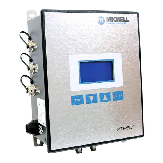
Figure 1 501 Analyzer and Transmitter The XTP501 Analyzer is based on Michell Instruments’ advanced proprietary Thermo- Paramagnetic technology. It measures the percentage of oxygen in a wide range of gases, including nitrogen, hydrogen, carbon dioxide, methane and biogas. The XTC501 Analyzer uses our thermal conductivity sensor to measure a target gas such as hydrogen in a background gas such as nitrogen. -
Page 10: Sensor Technologies
INTRODUCTION XTP501 & XTC501 User’s Manual Sensor Technologies 1.1.1 Thermo-paramagnetic Michell’s thermo-paramagnetic sensor uses a combination of paramagnetic and thermal conductivity techniques to accurately measure the oxygen content within a process gas. Oxygen is a paramagnetic gas, which means that it is attracted to a magnetic field. It is this property that can be exploited to help determine the level of oxygen in many background gases. -
Page 11: Thermal Conductivity
XTP501 & XTC501 User’s Manual INTRODUCTION 1.1.2 Thermal Conductivity Thermal conductivity (TC) is a property of all gases. This can be exploited as each gas has a different TC value and is used to determine the level of one gas in a binary or pseudo-binary mix. -
Page 12: Features
INTRODUCTION XTP501 & XTC501 User’s Manual Features • There are 2 versions of the 501 available: Analyzer with display and keypad Transmitter (base model) • The 501 is calibrated in a specific background gas to match customer's requirements. This is displayed on the front screen of the analyzer or via the Application Software. -
Page 13: Operation
XTP501 & XTC501 User’s Manual OPERATION OPERATION The 501 is not suitable for use with ambient oxygen levels that are enriched (i.e. over 21% O This analyzer has been manufactured within our quality procedures and is configured according to the purchase order. When it is installed and used as per the manufacturer’s guidelines, it will operate within the stated specification. -
Page 14: Powering Up The Analyzer
The analyzer takes up to 5 seconds to initialize, and during this period will display the product type and firmware version number. The transmitter version (XTP501- GP2) has a power interrupt button for use when connecting the optional remote display, approximately 10 minutes will be required for stabilization after powering back on. -
Page 15: User Interface
XTP501 & XTC501 User’s Manual OPERATION User Interface 2.3.1 Interface Controls Backlit LCD Up/Down ENTER Up/Down ENTER Button Arrow Button Button Arrow Button Buttons Buttons Figure 4 User Interface The images above illustrate the user-interface options, which consist of a backlit Liquid Crystal Display and 4 touch-sensitive pads that facilitate user interaction. -
Page 16: Esc' Button
XTP501 & XTC501 User’s Manual OPERATION 2.3.2 ‘ESC’ Button Figure 6 ESC Button The ESC button is used to exit the current menu and to return to the previous menu. From the Main Page, pressing ESC will access the Info Page. -
Page 17: Menu Structure
XTP501 & XTC501 User’s Manual OPERATION Menu Structure The analyzer has a front page that does not require a passcode but allows the user to scroll through and view oxygen/target gas concentration, recent trend, internal parameters, minimum & maximum concentration and alarm history. -
Page 18: Menu Map
XTP501 & XTC501 User’s Manual OPERATION 2.4.1 Menu Map Figure 9 Menu map 99976 Issue 1.1, May 2020... -
Page 19: Front Pages (No Passcode Required)
XTP501 & XTC501 User’s Manual OPERATION Front Pages (No Passcode Required) 2.5.1 Front Page Figure 10 Front Page XTP501 Parameter Description Displays the background gas that the unit was calibrated in Background Gas Real oxygen reading in % Display resolution = 0.01 (if HSR=OFF) (Display resolution 0.1% for suppressed zero ranges) - Page 20 XTP501 & XTC501 User’s Manual OPERATION Status Message Table Message Light Guide (Trigger Condition) (or target gas) out of range ORANGE1 ON (app s/w only) AL1 ON ORANGE2 ON (app s/w only) AL2 ON RED FLASH Comp i/p signal error (input <...
-
Page 21: Chart Page
XTP501 & XTC501 User’s Manual OPERATION 2.5.2 Chart Page Figure 11 Chart Page NOTE : This data is not available via the Modbus • This indicative chart is continuously running at the set chart interval (2 to 60 seconds). •... -
Page 22: Secondary Parameters Page
XTP501 & XTC501 User’s Manual OPERATION 2.5.3 Secondary Parameters Page CELL T, °C 50.0 PCB TEMP, °C COMP I/P EXT I/P Figure 12 Secondary Parameters Page Parameter Description Sensor cell temperature display in set unit (°C, °F or Kelvin) CELL T Display Resolution = 0.1... -
Page 23: Min/Max Page
XTP501 & XTC501 User’s Manual OPERATION 2.5.4 Min/Max Page MINIMUM 0.00 %CO2 D12/01 19:29:44 MAXIMUM 0.00 %CO2 D12/01 19:29:44 Figure 13 Min/Max Page This indicates the minimum and maximum values measured, along with date/time of occurrence. The value is reset manually via the Reset Page in the User Menu. -
Page 24: Info Page
XTP501 & XTC501 User’s Manual OPERATION Info Page Figure 15 Info Page From the Main Page it is possible to get to the Info Page by pressing the ESC button. The information available is displayed below Parameter Description Indicates the firmware version installed in the instrument... -
Page 25: Main Menu (Passcode Required)
XTP501 & XTC501 User’s Manual OPERATION Main Menu (Passcode Required) In order to change any settings on the User Menu pages, the user must enter a passcode. There is also a separate passcode for service engineers to allow factory setting changes. -
Page 26: Settings Page
XTP501 & XTC501 User’s Manual OPERATION 2.7.1 Settings Page Figure 17 Settings Pages for XTP (left) and XTC (right) The analyzer is microprocessor-based and, as such, has settings and features accessible to the user. Select the parameter required. The options will be highlighted and can be toggled between by pressing the ENTER button. -
Page 27: Human Machine Interface (Hmi) Page
XTP501 & XTC501 User’s Manual OPERATION 2.7.2 Human Machine Interface (HMI) Page 0-100% CONTRAST BRIGHTNESS 0-100% TEMPR UNIT C/F/K psia, bara, kpa EXT PRESS UNIT 2-60s CHART INTVAL DATE DD/MM/YY Figure 18 HMI Page It is possible to change parameters within the HMI, as shown below:... -
Page 28: Reset Page
XTP501 & XTC501 User’s Manual OPERATION 2.7.2.1 Date and Time Page HOURS 00-23 00-59 MINS 1-31 1-12 MONTH 00-99 YEAR **:**:** LIVE CLOCK Figure 19 Date and Time Page The real time clock and calendar is used to store date/time information for log data, min/max data and date of calibration. -
Page 29: Alarms Page
XTP501 & XTC501 User’s Manual OPERATION 2.7.4 Alarms Page Figure 21 Page Alarmes The analyser has 2 user-configurable alarms which are freely assignable within the calibrated range. The alarm relays are Single Pole Change-Over (SPCO) and are rated to 250 V, 5 A maximum. -
Page 30: External Compensation Page
XTP501 & XTC501 User’s Manual OPERATION 2.7.5 External Compensation Page Figure 22 External Compensation Page A 4–20 mA sensor may be used to compensate the % reading for the effects of process variables such as line pressure, flow, etc. The table of compensation factors may be edited for 5 points along the compensation sensor range. -
Page 31: External Sensor Page
XTP501 & XTC501 User’s Manual OPERATION 2.7.6 External Sensor Page Figure 23 External Sensor Page This page sets up the type and range of the 4–20 mA external sensor signal that may be connected to the XTP601 for viewing in the Main Page. The range is adjustable between the MIN and MAX values but is not adjustable for Other setting (fixed at 0% and 100%). -
Page 32: Outputs Page
XTP501 & XTC501 User’s Manual OPERATION 2.7.7 Outputs Page Figure 24 Outputs Page The analyzer has two 4-20 mA outputs and two concentration alarm relays. The primary 4-20 mA is fixed to the calibrated range of the unit, the second is freely selectable from 0 to 100%. -
Page 33: Field Cal Page
XTP501 & XTC501 User’s Manual OPERATION 2.7.7.1 NAMUR Output Set-Up NAMUR ERR LOW/HIGH Figure 25 NAMUR ERR Page During initial warm up, or in the event of a sudden change of cell temperature beyond 0.5°C from the set point, the mA output will be driven to an alarm state of either 3.5 mA or 21.5 mA. -
Page 34: Light Guide
XTP501 & XTC501 User’s Manual OPERATION 2.7.9 Light Guide The light guide is fitted to the right-hand side of the lower surface and has a red and green LED to display the current status. • Green On – indicates instrument power is on. -
Page 35: Calibration
NOTE: Analyzers are calibrated in background gas suitable for the specific application. Customer's calibration gases must match the process gas. Please refer to Test Result Sheet or a Michell Instruments' representative. For range 0 to 25% the analyzer will have calibration points between 0 and 21% and will retain specification up to 23% O . -
Page 36: 1-Point Calibration
XTP501 & XTC501 User’s Manual CALIBRATION 1-point Calibration This is a single point offset overlaid on top of the factory calibration. It is designed to correct minor drift and minor changes during transit. This calibration makes the unit very accurate at the calibration point and improves accuracy throughout the range. -
Page 37: 2-Point Calibration
XTP501 & XTC501 User’s Manual CALIBRATION 2-Point Calibration This is a 2-point adjustment that is overlaid on top of the factory calibration. It is designed to correct minor drift and minor changes during transit. This calibration makes the unit more accurate throughout the range than the single point calibration. -
Page 38: Field Calibration Reset
XTP501 & XTC501 User’s Manual CALIBRATION Field Calibration Reset The Field Calibration can simply be turned ON or OFF in the settings page. But if the user would like to start again, the Field Cal (including saved data) can be deleted in this menu. -
Page 39: Installation
XTP501 & XTC501 User’s Manual INSTALLATION INSTALLATION Before installing the analyzer, read through this manual carefully and take note of all warnings. Unpacking If sold separately (not part of a sampling system), the 501 will be supplied in a custom box which should be retained for future use (such as service return). -
Page 40: System Components
The 501 Analyzer benefits from a modular construction, with the major parts of the analyzer shown below: Figure 30 XTP501 and XTC501 Showing Major Components Inputs (2 x 4–20 mA) Outputs (2 x 4–20 mA + RS485) Alarms (2 x concentration alarms) -
Page 41: Set-Up
XTP501 & XTC501 User’s Manual INSTALLATION Set-Up • The 501 is designed to be wall mounted via 4 bolt holes. Dimensional drawings can be found in Appendix A. WARNING: This unit is 24 V DC powered only! Do not attempt to loop-power this instrument via the 4–20mA output as this will irreversibly damage... -
Page 42: Gas Connection
INSTALLATION XTP501 & XTC501 User’s Manual 4.4.1 Gas Connection The gas connections are on the bottom surface in the centre of the unit. The gas inlet is the right-hand connection when viewing the unit from the front. 501 models have 1/8’’... -
Page 43: Electrical Installation
XTP501 & XTC501 User’s Manual INSTALLATION Electrical Installation 4.5.1 Power Supply and Input/Output Signal The 501 requires 24 V DC power input at a maximum start-up current of 1.5 A. NOTE : Loose connectors are supplied with the analyser for Power, Inputs, Outputs and Alarms. -
Page 44: Signal Output
INSTALLATION XTP501 & XTC501 User’s Manual 4.5.3 Signal Output There are two 4-20mA linear signal output channels for target gas concentration. One is fixed on the calibrated range of the unit and the second can be configured in the menu. -
Page 45: Alarm Relay Contacts
XTP501 & XTC501 User’s Manual INSTALLATION NOTE 1: Channel 1 is fixed range output over instrument range and Channel 2 is adjustable between 0–100%. NOTE 2: The maximum loop load resistance for mA outputs is 550Ω. NOTE 3: The mA outputs are powered with a 24V excitation voltage. -
Page 46: Analog (4-20 Ma) Inputs And Sensor Excitation Voltage
XTP501 & XTC501 User’s Manual APPENDIX A 4.5.7 Analog (4–20 mA) Inputs and Sensor Excitation Voltage Pin Number Description Colour Channel 2 -VE White Channel 2 +VE Yellow Channel 1 Feed Green Channel 1 +VE Blue Channel 1 -VE Channel 2 Feed... - Page 47 XTP501 & XTC501 User’s Manual APPENDIX A Appendix A Technical Specifications Michell Instruments...
-
Page 48: Appendix A Technical Specifications
Standard +50°C (+113°F) Background Gas Analyzer is calibrated in the background gas of the process. The XTP501 process oxygen analyzer meets or exceeds all relevant clauses in BS EN 50104: 2010 “Electrical apparatus for the detection and measurement of oxygen”. Performance (XTC501) -
Page 49: Figure 33 501 Dimensional Drawings - Gp1
XTP501 & XTC501 User’s Manual APPENDIX A Common Features and Specifications Electrical Specifications Display Type Backlit LCD (GP1 model only) 0.01% Display Resolution 0.1% for XTP with suppressed zero ranges or XTC ranges > 10% 2 off 4–20 mA inputs... -
Page 50: Dimensions
XTP501 & XTC501 User’s Manual APPENDIX A Dimensions 180mm 7.09" 165mm 6.50" 155mm 6.10" 24mm 0.93" 10mm 0.39" 1/8" Tube fitting 6mm 0.24" Max screw diameter 25mm 1.00" 69mm 2.71" 99mm 3.89" THIS DOCUMENT IS THE PROPERTY OF MICHELL MATERIAL: Figure 33 501 Dimensional Drawings –... -
Page 51: Figure 34 501 Dimensional Drawings - Gp2
XTP501 & XTC501 User’s Manual APPENDIX A 180mm 7.09" 165mm 6.50" 155mm 6.10" 24mm 0.93" 10mm 0.39" 6mm 0.24" Max screw diameter 1/8" Tube fitting 25mm 1.00" 69mm 2.71" 99mm 3.89" Figure 34 501 Dimensional Drawings – GP2 THIS DOCUMENT IS THE PROPERTY OF MICHELL MATERIAL: INSTRUMENTS LTD. - Page 52 APPENDIX B XTP501 & XTC501 User’s Manual Appendix B Quality, Recycling, Compliance & Warranty Information 99976 Issue 1.1, May 2020...
-
Page 53: Appendix B Quality, Recycling, Compliance & Warranty Information
APPENDIX B Appendix B Quality, Recycling, Compliance & Warranty Information Michell Instruments is dedicated to complying to all relevant legislation and directives. Full information can be found on our website at: www.michell.com/compliance This page contains information on the following directives: •... - Page 54 APPENDIX C XTP501 & XTC501 User’s Manual Appendix C Analyzer Return Document & Decontamination Declaration 99976 Issue 1.1, May 2020...
-
Page 55: Appendix C Analyzer Return Document & Decontamination Declaration
Has the equipment been cleaned and decontaminated? NOT NECESSARY Michell Instruments will not accept instruments that have been exposed to toxins, radio-activity or bio-hazardous materials. For most applications involving solvents, acidic, basic, flammable or toxic gases a simple purge with dry gas (dew point <-30°C) over 24 hours should be sufficient to decontaminate the unit prior to return. - Page 56 http://www.michell.com...
Need help?
Do you have a question about the XTP501 and is the answer not in the manual?
Questions and answers