
Related Manuals for Michell Instruments XZR250


Summary of Contents for Michell Instruments XZR250
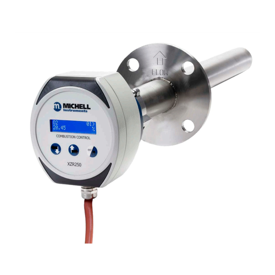
- Page 1 XZR250 User’s Manual PRODUCT OVERVIEW XZR250 Oxygen Analyzer User’s Manual 97528 Issue 5 May 2019 Michell Instruments...
- Page 2 XZR250 User’s Manual Please fill out the form(s) below for each instrument that has been purchased. Use this information when contacting Michell Instruments for service purposes. Instrument Code Serial Number Invoice Date Location of Instrument Tag No Instrument Code Serial Number...
- Page 3 XZR250 User’s Manual XZR250 For Michell Instruments' contact information please go to www.michell.com Michell Instruments...
-
Page 4: Table Of Contents
XZR250 User’s Manual Contents Safety ..........................vi Electrical Safety ......................vi Pressure Safety ......................vi Toxic Materials ......................vi Repair and Maintenance ....................vi Calibration ........................vi Safety Conformity ......................vi Abbreviations ........................vii Warnings .......................... viii PRODUCT OVERVIEW ..................1 Components ....................... 1 INSTALLATION ....................2 General Guidelines ....................2 Electrical Connections .................. - Page 5 XZR250 User’s Manual RELAY AND CURRENT TESTING ................26 Relay test ......................26 Current Test ..................... 27 ERROR CONDITIONS ..................29 Error and Warning Codes ................29 Pressure Error and Warning Codes ..............29 Temperature Error and Warning Codes ............... 29 REPLACING PARTS ...................30 Removing the Sensor head from the Probe ............
-
Page 6: Safety
Michell Instruments’ worldwide offices contact information. Calibration The recommended calibration interval for the XZR250 is between one and three months. This duration may be shorter or longer dependent on installation, application and customer preferences. Safety Conformity This product meets the essential protection requirements of the relevant EU directives. -
Page 7: Abbreviations
XZR250 User’s Manual Abbreviations The following abbreviations are used in this manual: °C degrees Celsius °F degrees Fahrenheit direct current European Union kilogram(s) l/min liters per minute pound milliampere maximum minute(s) scfh standard cubic feet per hour cycle time to evacuate and re-pressurize the sealed cell... -
Page 8: Warnings
INFORMATION Do not exceed maximum ratings and As customer applications are outside of ensure sensor(s) are operated in Michell Instruments Ltd.’s control, the accordance with their requirements. information provided is given without legal Carefully follow all wiring instructions. responsibility. Customers should test under... -
Page 9: Product Overview
The XZR250 is designed to allow direct installation of the probe in the wall of a flue or furnace to measure the concentration of oxygen in the stack gas with temperatures up to 700°C. -
Page 10: Installation
XZR250 User’s Manual INSTALLATION INSTALLATION To ensure the best performance from your equipment, it must be installed correctly. General Guidelines Mount the probe so that the tip is in the main stream of gas (within the flue), as close to the burner as possible, but not within the flame. Ensure the maximum temperature is within the temperature limits of the probe. -
Page 11: Electrical Connections
XZR250 User’s Manual INSTALLATION Electrical Connections Remove the front panel: If fitted, carefully remove the two screw covers (2) from the front panel (1). Remove the four screws securing the front panel (1) to the housing. Carefully ease the front panel (1) from the housing. -
Page 12: Figure 3 Cable Shielding
XZR250 User’s Manual INSTALLATION CAUTION: Make sure the shielding is intact and correctly positioned to ensure the device is grounded properly as shown below. Figure 3 Cable Shielding Using a 20mm spanner, tighten the cable gland to secure the cable in place. -
Page 13: Figure 4 Connector Pins
XZR250 User’s Manual INSTALLATION Connect the wires as follows (refer to Figure 4 below): Figure 4 Connector Pins Power Supply PIN 1: 24V DC PIN 2: OV RS485 Output PIN 3: A PIN 4: B Analog Output The mA outputs are powered with 24V excitation voltage and the maximum loop load resistance for mA output 550 Ω... -
Page 14: Mounting Instructions
XZR250 User’s Manual INSTALLATION Mounting Instructions The probe should be mounted such that the alignment arrow on the flange is in the same direction as the sample gas flow. Refer to Figure 5 showing alignment arrow. Avoid positions where: •... -
Page 15: Figure 6 Mounting Adaptor Details
XZR250 User’s Manual INSTALLATION Mounting Adaptor Details Figure 6 NOTE: The probe should be mounted horizontally, or ideally at an angle of approximately 5° to the flue wall as shown in figure 6. Mounting Examples Figure 7 CAUTION: The gas temperature must not exceed 700°C for prolonged periods. -
Page 16: Probe Installation
XZR250 User’s Manual INSTALLATION Probe Installation CAUTION: Do not mount the probe at an angle that would allow liquid to run down towards the sensor head, as this may cause blockage or damage. NOTE: A suitable 2” ANSI flange mounting adaptor is required. If the application temperatures will exceed 200°C, use an anti-seize compound on any mounting threads to ease future... -
Page 17: Figure 9 Insert Sensing Module
XZR250 User’s Manual INSTALLATION Figure 9 Insert Sensing Module Ensure housing is wired correctly; refer to section 2.2 Electrical Connections. Hold the sensor head with the display facing downwards. Fit sensing module to the sensor head and gently push to secure the module in place;... -
Page 18: Initial Startup
XZR250 User’s Manual INITIAL STARTUP INITIAL STARTUP Commissioning Checks Before commissioning the equipment please read safety instructions. Complete the following essential tasks BEFORE switching the system ON for the first time: • Ensure the analyzer is installed in the correct orientation. -
Page 19: System Elements
XZR250 User’s Manual SYSTEM CONFIGURATION SYSTEM ELEMENTS The XZR250 combustion control analyzer consists of three main elements: • A probe to extract the sample. • A sensor block to measure the gas (contains O , pressure & temperature sensors) •... -
Page 20: Table 2 Operator Panel Multifunctional Buttons
XZR250 User’s Manual SYSTEM CONFIGURATION The buttons are multifunctional: Primary Secondary Tertiary Scroll left Scroll down Scroll right Scroll up Back one level. Return to the home screen. Enter Press and hold until screen Press and hold until screen flashes twice... -
Page 21: On-Screen Settings
XZR250 User’s Manual SYSTEM CONFIGURATION On-Screen Settings The following parameters are displayed on-screen: LCD Layout Figure 12 Top left: Measured parameter Lower left: Measurement value Top right: Position within the menu structure Lower right: Unit of measure NOTE: From the main screen it is possible to scroll up to view pressure and temperature. -
Page 22: Menu Structure
XZR250 User’s Manual SYSTEM CONFIGURATION Menu Structure HOME SCREEN DESCRIPTION 01> Displays the O concentration level (%) Pressure <02> Displays the pressure (mbar) at the sensing element Temperature <03 Displays the gas temperature (°C) at the sensing element Enter password to access below (default password is 0000) -
Page 23: Configurable Options
XZR250 User’s Manual SYSTEM CONFIGURATION Configurable Options The menu screens are primarily for information although there are user configurable options that may be changed. These are as follows: • Password • Calibration gas concentration • Analog output ranges • Alarm relay 1 •... - Page 24 XZR250 User’s Manual SYSTEM CONFIGURATION Now use the up arrow to ge to menu item <05 SYSTEM press <ENTER> this brings you to the next level down and will display SERIAL NUM 01>. Scroll up to PASSWORD <05> and press <ENTER>.
-
Page 25: Analog Output Ranges
XZR250 User’s Manual SYSTEM CONFIGURATION Analog Output Ranges The device is factory set to output a range of 0 – 25% O via its analog output. The output ranges can be fully customised; this is extremely useful in applications where the O variation is within a narrow band as it allows the analog outputs to be tailored to this limited range. -
Page 26: Display Output
XZR250 User’s Manual SYSTEM CONFIGURATION Press <ENTER> to access edit mode. Input the Lower range value: the number must be less than the intended upper range value. Press <ENTER> to save. Input the Upper range value: the number must be greater than the saved lower value. - Page 27 XZR250 User’s Manual SYSTEM CONFIGURATION Press the <RIGHT> button five times until the SYSTEM screen is displayed. Press <ENTER> to access the SYSTEM menu. Press <RIGHT> 6 times until the HOME SETUP screen is displayed. Press <ENTER> to access edit mode.
-
Page 28: Operational Considerations
XZR250 User’s Manual OPERATION OPERATIONAL CONSIDERATIONS Environments The application in which the zirconium oxide oxygen sensor is operating influences the life of the sensor. To ensure the sensor does not fail prematurely, the following should be noted: 5.1.1 Operating in Aggressive and Humid Environments... -
Page 29: Combustible Gases
XZR250 User’s Manual OPERATION 5.2.1 Combustible Gases Small amounts of combustible gases will be burned at the hot Pt-electrode surfaces or Al2O filters of the sensor. In general, combustion will be stoichiometric as long as enough oxygen is available, the sensor will measure the residual oxygen pressure which leads to a measurement error. -
Page 30: Maintenance
XZR250 User’s Manual MAINTENANCE MAINTENANCE WARNING: BEFORE performing any type of maintenance on the equipment read the safety instructions. Ensure the device has cooled down completely before attempting to touch or service the equipment. Cleaning 6.1.1 Outer Surfaces Inspect the outer surfaces of the sensor head regularly, and clean with non-abrasive materials to prevent a buildup of contaminants. -
Page 31: Calibrating
NOTE: The sensor has a finite life span ranging from 1-7 years depended on the fuel type used in the boiler. Michell Instruments operates a service exchange program, for more details please contact your local Michell office or representative. NOTE:... -
Page 32: Calibration Gas Requirements
XZR250 User’s Manual MAINTENANCE 6.2.1 Calibration gas requirements Clean dry gas (dew point <-20°C) with an oxygen content between 2% and 21% at a nominal flow rate of 150ml/min. Remove the plug from the gas inlet port on the sensor head and connect the calibration gas supply with 4mm tubing via a push fit connection. - Page 33 XZR250 User’s Manual MAINTENANCE Press <ENTER> again to apply. The device will run through the calibration routine and return the following status message when complete. The output will now track to the correct value for the calibration gas. The new calibration value is now stored in memory and is retained on power loss.
-
Page 34: Relay And Current Testing
XZR250 User’s Manual RELAY AND CURRENT TESTING RELAY AND CURRENT TESTING During commissioning and annual maintenance it is advisable to check the relays and 4-20mA are working and correctly set. The following test procedures allow the user to perform these function tests. -
Page 35: Current Test
RELAY AND CURRENT TESTING XZR250 User’s Manual With the STOP screen displayed, press <RIGHT> to tab along to the asterisk (*): Press <ENTER> to stop the test process and switch the relay OFF. Current Test Its possible to test the current outputs following the procedure below: Press <ENTER>: the ENTER PASSWORD screen is displayed. - Page 36 XZR250 User’s Manual RELAY AND CURRENT TESTING Input the START value (between 4 and 20mA), then press <RIGHT> to tab along to the asterisk (*). Press <ENTER> to start testing. With the STOP screen displayed, press <RIGHT> to tab along to the asterisk (*).
-
Page 37: Error Conditions
XZR250 User’s Manual ERROR CONDITIONS ERROR CONDITIONS If an error is detected, an error code appears on the digital display. If the zirconia sensor is incorrectly connected or is damaged, in addition to the error message, the analog output will default to 4mA. -
Page 38: Replacing Parts
XZR250 User’s Manual REPLACING PARTS REPLACING PARTS WARNING: BEFORE performing any type of maintenance on the equipment read the safety instructions. WARNING: Ensure the probe has cooled down completely before attempting to dismantle. Figure 13 Components Parts List Tools (If necessary) Sensor Head •... -
Page 39: Removing The Sensor Head From The Probe
XZR250 User’s Manual REPLACING PARTS Removing the Sensor head from the Probe Refer to Figure 13; component numbers given in parenthesis. Shut-down and isolate the power supply and allow the probe to cool down. WARNING: Ensure the probe has cooled down completely before trying to remove the sensor head. -
Page 40: Replacing The Zirconia Sensor Block
XZR250 User’s Manual REPLACING PARTS CAUTION: The sensor head (1) is a tight fit to the probe body (4): do NOT use tooling of any kind to drive it home. NEVER strike the housing, this may cause irreparable damage. With the cable gland at the base of the sensor head (1) facing downwards, tighten clamp (2) to secure the sensor head (1) in place. -
Page 41: Removing / Replacing The Front Panel
XZR250 User’s Manual REPLACING PARTS Thoroughly clean the surfaces of the housing body to prevent contamination entering the inner assemblies. Align and install the new zirconia sensing module (6) to the sensor head (1). Gently push to secure the module in place: refer to Figure 14. -
Page 42: Disposal
XZR250 User’s Manual REPLACING PARTS CAUTION: Do NOT pull forcefully. Disconnect the ribbon cable from the old panel and connect to the new front panel. Re-fit the front panel (1) to the housing and secure in place using the four screws. - Page 43 XZR250 User’s Manual APPENDIX A Appendix A Technical Specifications Michell Instruments...
-
Page 44: Appendix A Technical Specifications
XZR250 User’s Manual APPENDIX A Appendix A Technical Specifications Performance Measurement technology Zirconium Oxide Oxygen Measurement range 0.1-25% Output resolution 0.01 V, 0.01 mA or 0.01% O Accuracy (0.25-25%) < 0.25% O Response time (T90) < 15 seconds Repeatability < 0.25% Sample flow effect ±0.5% of full scale... -
Page 45: Figure 15 External Dimensions
XZR250 User’s Manual APPENDIX A *Measurement chamber temperature and pressure can be displayed on the main screen but can also be output via the MODBUS. The second mA output can be factory configured for pressure or as a second O output. - Page 46 XZR250 User’s Manual APPENDIX B Appendix B Theory of Operation 97528 Issue 5, May 2019...
-
Page 47: Appendix B Theory Of Operation
XZR250 User’s Manual APPENDIX B Appendix B Theory of Operation The sensor employs a well-proven, small Zirconium oxide-based element at its heart that does not require a reference gas. This removes limitations in the environments in which the sensor can be operated, making high temperatures, humidity and oxygen pressures all possible. - Page 48 Chamber Platinum Ring At the core of the XZR250 oxygen analyzer is a cell consisting of two Zirconium oxide (ZrO ) squares coated with a thin porous layer of platinum which serve as electrodes. The platinum electrodes provide the catalyst necessary for the measured oxygen to...
- Page 49 XZR250 User’s Manual APPENDIX B COMMON PARTIAL PRESSURE TO BE MEASURED) (CHAMBER PRESSURE) SENSE SENSE PUMP Sensing Plate: A difference in oxygen pressure across the second ZrO square generates a Nernst voltage which is logarithmically proportional to the ratio of the oxygen ion concentrations (see Nernst Voltage).
- Page 50 XZR250 User’s Manual APPENDIX C Appendix C Quality, Recycling & Warranty Information 97528 Issue 5, May 2019...
-
Page 51: Appendix C Quality, Recycling & Warranty Information
XZR250 User’s Manual APPENDIX C Appendix C Quality, Recycling & Warranty Information Michell Instruments is dedicated to complying to all relevant legislation and directives. Full information can be found on our website at: www.michell.com/compliance This page contains information on the following directives: •... - Page 52 XZR250 User’s Manual APPENDIX D Appendix D Analyzer Return Document & Decontamination Declaration 97528 Issue 5, May 2019...
-
Page 53: Appendix D Analyzer Return Document & Decontamination Declaration
Has the equipment been cleaned and decontaminated? NOT NECESSARY Michell Instruments will not accept instruments that have been exposed to toxins, radio-activity or bio-hazardous materials. For most applications involving solvents, acidic, basic, flammable or toxic gases a simple purge with dry gas (dew point <-30°C) over 24 hours should be sufficient to decontaminate the unit prior to return. - Page 54 http://www.michell.com...
Need help?
Do you have a question about the XZR250 and is the answer not in the manual?
Questions and answers