
Related Manuals for Otto Bock 17AD100 Nexgear Tango


Summary of Contents for Otto Bock 17AD100 Nexgear Tango
- Page 1 17AD100 Nexgear Tango ankle joint Fabricating an ankle-foot orthosis and installing the modules Technical information 5.2.4...
- Page 2 Introduction English 1 Introduction This technical information supports you in the fabrication of an ankle-foot orthosis using lamination resin techno logy. This document is directed to trained prosthetists. It is a prerequisite that the qualified personnel are trained in the handling of the various materials, machines and tools.
- Page 3 Procedure Materials Designation Reference number Wax pen 633W8 Carbon-fibreglass webbing 616H10=* Carbon fibre stockinette 616G15=* Dacron felt 616G6 Quick-drying adhesive 636K11 Polyethylene adhesive tape 627B4 Plastaband 636K8 Double-sided PVC adhesive tape 616F10* Spray adhesive 636K40 Isopropyl alcohol 634A58 C-Orthocryl lamination resin 617H55 Hardening powder 617P37=0.150...
- Page 4 Procedure Insert the foot stirrup into the lamination dummy cover, leaving the bearing bushing in the foot stirrup. Slide the lamination dummy cover with the shoulder screw onto the lower part of the lamination dummy and mark the insertion zone on the bar and foot stirrup. Remove the bar and foot stirrup from the lamination dummy for machining.
- Page 5 Procedure Check the distance between the lamination bar/foot stirrup and the plaster model. The minimum distance must be approx. 2 to 3 mm. Deburr the bar and foot stirrup. Reinforce the supporting surface with PVC profile material. Heat the PVC profile material with a hot air gun and mould it into shape.
- Page 6 Procedure Glue the profile material to the lamination bar. Firmly press the gluing surfaces together. 3.3 Reinforcing Bar and clamp INFORMATION: Before reinforcing, roughen the bar and foot stirrup and clean them using a degreasing cleaner. Reinforce the foot stirrup with carbon fibre stockinette, letting the woven stockinette project approx.
- Page 7 Procedure Isolate the following components with wax in the area of the joints: • Lamination dummy – lower part • Bar/foot stirrup insertion zone • Screws Connect the isolated components to each other. Orthosis Use Plastaband to even out the sharp edges of the alignment insert.
- Page 8 Procedure Pull a soaked PVA bag over the plaster model. Apply polyethylene adhesive tape over the alignment insert so the PVA bag does not tear later while screw ing on the dummy. Pull 1 layer of Perlon stockinette over the plaster model. Apply contact adhesive to the stockinette above the alignment insert.
- Page 9 Procedure NOTE: Use as little adhesive tape or spray adhes ive as possible, so that the fibres are thoroughly soaked during laminating. Secure the carbon-fibreglass webbing to the Perlon stockinette with some double-sided adhesive tape or spray adhesive. • Apply 1 layer of carbon-fibreglass webbing as full- surface reinforcement from the heel to the rollover edge in a – p direction.
- Page 10 Procedure Secure the reinforced components to the alignment insert using the shoulder screw. Fan out the end of the carbon fibre stockinette. Secure the fanned-out fibres to the reinforcement with carbon-fibreglass webbing. Fan out the end of the carbon fibre stockinette and secure it with carbon-fibreglass webbing.
- Page 11 Procedure Fill the cavities between the plaster model and lamina tion bar/foot stirrup with Dacron felt. Seal and level off all screws and protrusions on the plaster model with Pastasil. Pull 1 layer of Perlon stockinette over the plaster model. Apply 1 layer of carbon fibre cloth in the area of the tibia support surface.
- Page 12 Procedure Optional: Fabricate a long foot component. • Cut 2 layers of carbon fibre cloth to size (fibre ori entation: 45°). • Position the carbon fibre cloth on the foot compon ent. INFORMATION: A flexible forefoot component is fabricated in this example. Position carbon-fibreglass webbing from the heel to the rollover edge in a - pandm - l direction.
- Page 13 Procedure Secure the blanks on the model. Then pull a thin stockinette over the model. INFORMATION: The stockinette prevents the car bon fibre cloth layers from slipping while pulling the PVA bag over the model. In addition, the stock inette ensures that the lamination resin is distrib uted more quickly over the reinforcement.
- Page 14 Procedure 3.4 Laminating and finishing Turn on the vacuum and check the PVA bag to make sure there are no leaks. Mix the lamination resin with the hardener. NOTICE: To avoid overheating during curing, no more than 1.5% hardener should be added. Carry out the lamination process.
- Page 15 Procedure Remove the lamination dummy cover. If the bearing bushing was removed with the lamination dummy cover, reinsert the bearing bushing into the foot stirrup. Cut the orthosis open along the marked course of the edge using an oscillating saw and remove it from the plaster model.
- Page 16 Procedure The shape of the lamination dummy produces the desired contour to enable the full range of motion of the orthosis joint without damaging the laminate. 3.5 Mounting the orthosis joint Check the fit of the bearing bushing in the foot stirrup, or install the bearing bushing if it is missing.
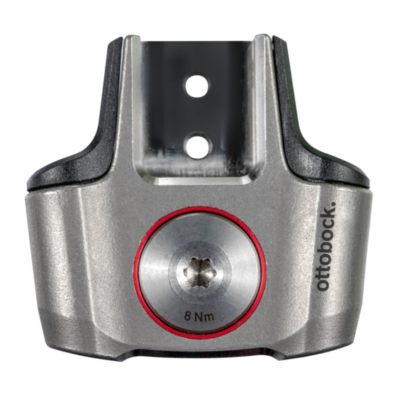
- Page 17 Procedure Insert the joint screw and joint nut, and tighten with a Torx wrench. 3 Nm 3 Nm 5 Nm 8 Nm 8 Nm 3.6 Installing the spring-module Insert the threaded hole through the cover from above and screw it into the basic piece. NOTE: Use vice jaws to prevent damage to the product while clamping it in the vice.
- Page 18 Procedure Insert the ball into the threaded hole. Slide the spring into the spring guide housing and posi tion it in the threaded hole. Screw the setscrew into the threaded hole and tighten with a Torx wrench. 17AD100...
- Page 19 Procedure 3.7 Installing the stop-module Insert the threaded hole through the cover from above and screw it into the basic piece so that the flattened side of the cover faces the basic piece. NOTE: Use vice jaws to prevent damage to the product while clamping it in the vice.
- Page 20 Procedure Screw the setscrew into the threaded hole and set it to the desired position. 3.8 Installing the reaction-module INFORMATION: The Nexgear Tango Reaction-mod ule is delivered installed in the cover. Before the module can be installed in the orthosis joint, it has to be disassembled into the individual compon...
- Page 21 Procedure Loosen the spring bolt and remove the spring dummy from the spring holder. Remove the washer. Unscrew the spring holder from the support element. INFORMATION: The stop pin is provided with a thread lock and is therefore difficult to turn during adjustment.
- Page 22 Procedure Place the mounting adapter onto the support element and slide it through the cover. Set the flattened side of the cover onto the base body. Tighten the support element to the corresponding torque value. Then remove the mounting adapter. Insert the spring plunger with the bearing sleeve and stop pin into the cover in the support element.
- Page 23 Procedure NOTE: To avoid damaging the fine thread, ensure proper alignment and smooth movement while screwing it in. Use a Torx wrench to screw the spring holder into the internal thread of the support element. Set the torque wrench with bit extension onto the spring holder and tighten it.
- Page 24 Procedure Place the spring bolt on the module and tighten it with a Torx wrench until the spring dummy fits in the module with no play. 3.9 Reaction-module – static alignment Put the orthosis on the patient. Use the knee pivot point gauge to determine and mark the compromise pivot point according to Nietert on the knee joint.
- Page 25 Procedure Pass the Torx wrench through the spring bolt to adjust the stop. Relieve the lower leg by hand so that the stop pin can move easily in the thread. INFORMATION: When using 2 reaction-modules, adjust the orthosis joint until it no longer has any play in the a - p direction.
- Page 26 Procedure 3.10 Reaction-module – dynamic alignment For the dynamic trial fitting, unscrew the spring bolt with a Torx wrench and replace the spring dummy with the reaction-spring. Install the spring bolt. Screw in the spring bolt flush with the cover using a Torx wrench.
- Page 27 Procedure Carrying out the dynamic trial fitting: • Put the orthosis on the patient. • Check the sagittal alignment of the orthosis on the patient using the L.A.S.A.R. Posture. • Set the desired pretension of the reaction-spring using the spring bolt. •...
- Page 28 Procedure • Adjust the stop of Reaction-module 3. If Reaction- module 1 is present, adjust the stop to be identical to Reaction-module 1. • Now retighten the previously loosened spring bolt of Reaction-module 1. • If Reaction-module 4 is to be adjusted: Loosen the spring bolt of Reaction-module 2.
- Page 29 17AD100...
- Page 30 17AD100...
- Page 31 T +49 5527 848-3455 · F +49 5527 848-1510 Otto Bock France SNC healthcare@ottobock.de · www.ottobock.de 4 rue de la Réunion - CS 90011 Industria Ortopédica Otto Bock Unip. Lda. 91978 Courtaboeuf Cedex · France Av. Miguel Bombarda, 21 - 2º Esq. Otto Bock HealthCare Deutschland GmbH T +33 1 69188830 · F +33 1 69071802 1050-161 Lisboa ·...
- Page 32 Printed by: Ottobock SE & Co. KGaA Max-Näder-Straße 15 · 37115 Duderstadt · Germany T +49 5527 848-0 · F +49 5527 848-3360 healthcare@ottobock.de · www.ottobock.com...
Need help?
Do you have a question about the 17AD100 Nexgear Tango and is the answer not in the manual?
Questions and answers