
Subscribe to Our Youtube Channel
Related Manuals for Newport CONEX-PP Series


Summary of Contents for Newport CONEX-PP Series
- Page 1 CONEX-PP Single-Axis Intelligent Stepper Motor Controller/Driver Controller GUI Manual V1.0.x...
-
Page 2: Warranty
Controller GUI Manual Warranty Newport Corporation warrants that this product will be free from defects in material and workmanship and will comply with Newport’s published specifications at the time of sale for a period of one year from date of shipment. If found to be defective during the warranty period, the product will either be repaired or replaced at Newport's option. -
Page 3: Table Of Contents
Components ....................... 3 2.1.2 Electrical Installation ....................4 First Connection ......................... 5 2.2.1 CONEX-PP Series USB Driver Installation on Windows 7 ........5 USB Driver Installation Verification ................. 6 Discover Instruments ......................7 3.0 User Interface ....................8 Configuration ........................8 Main .......................... - Page 4 CONEX-PP Controller GUI Manual EDH0350En1031 – 12/18...
-
Page 5: Ec Declaration Of Conformity
CONEX-PP Controller GUI Manual EC Declaration of Conformity EDH0350En1031 – 12/18... - Page 6 CONEX-PP Controller GUI Manual EDH0350En1031 – 12/18...
-
Page 7: Introduction
GUI. Overview The CONEX-PP series GUI is a graphical user interface (GUI) which allows the user to interact with the controller that is integrated with intelligent stepper motor stages. The user can initiate moves, change the state of the controller, adjust configuration parameters, etc. -
Page 8: Controller State Diagram
CONEX-PP Controller GUI Manual Controller State Diagram The CONEX-PP controller is defined by the following state diagram. Actions in each state when End of Runs is encountered NOT REFERENCED: No action. CONFIGURATION: No action. HOMING: Only check at end of HOMING and then change to NOT REFERENCED state. -
Page 9: Getting Started
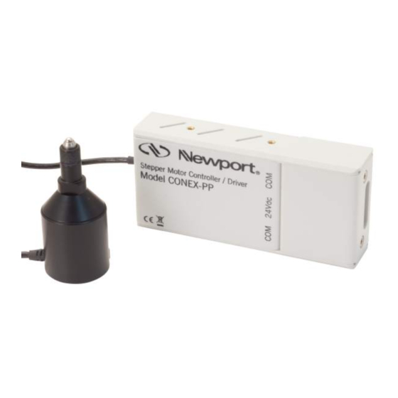
CONEX-PP Controller GUI Manual Getting Started Overview and Setup 2.1.1 Components USB-RS422-1.8 USB Adaptor FC-PS40 Power Supply CONEX-PP Series Intelligent Stepper Motor Stages EDH0350En1031 – 12/18... -
Page 10: Electrical Installation
Controller GUI Manual 2.1.2 Electrical Installation 1. Connect the USB-RS422-1.8 adaptor cable to the CONEX-PP series stage. 2. Connect the FC-PS40 power supply to the CONEX-PP series stage. 3. Connect the USB cable to an available USB port of the PC 4. -
Page 11: First Connection
VERIFY THAT YOU HAVE THE APPROPRIATE RIGHTS 2.2.1 CONEX-PP Series USB Driver Installation on Windows 7 1. Connect the CONEX-PP controller to a USB port with the USB cable. 2. Detection of this new connected device (the first time) is signaled by a message in the bottom-right of the screen. -
Page 12: Usb Driver Installation Verification
CONEX-PP Controller GUI Manual USB Driver Installation Verification Open the “Device Manager” and select the “Device” tab to check your configuration. In the display menu, select “View devices by type”. Expand “USB Bus controllers” line and check the new line USB Serial Converter: Expand “Ports (COM and LPT)”... -
Page 13: Discover Instruments
CONEX-PP Controller GUI Manual Discover Instruments Start the Controller GUI from Newport\MotionControl\CONEX-PP. Next, click on “Discover” and the number of stages discovered will appear. This window allows the user to select a COM port where the desired stage is connected. -
Page 14: User Interface
Controller GUI will only log errors that are defined to be critical. The polling interval defines the number of milliseconds between each time the Controller GUI polls the CONEX-PP series for the latest information. The user may change the polling interval by entering a value. Diagnostics Delay defines the time delay in milliseconds between each command sent from a text file. - Page 15 CONEX-PP Controller GUI Manual Configurable settings The following table describes all the settings that can be changed by the user. Parameter Description Values / Type Default LoggingConfiguration Level Logging level. Trace Trace Trace is the most detailed of the settings and Detail when this setting is selected the applet logs Equipment Message...
-
Page 16: Main
CONEX-PP Controller GUI Manual Main The Main tab displays the main controls in the Controller GUI like a virtual front panel. It is updated each time the polling interval timer expires. “Initialization and Configuration” In the “Initialization and Configuration” area, the first button changes the controller status to “Enabled”... - Page 17 CONEX-PP Controller GUI Manual “Cyclic Motion” and “Target position / PA” In the “Cyclic Motion” area, a motion cycle is configured with a number of cycles (Cycle) and a dwell time in milliseconds. The motion cycle gets the defined target positions from the “Target Motion / PA”...
-
Page 18: Parameters
CONEX-PP Controller GUI Manual Parameters The Parameters tab displays the stage parameters for the selected controller. Note modification of parameters is disabled in the Parameters tab. User configuration parameter such as velocity, acceleration and End of Runs can be changed in the main tab. -
Page 19: Address
CONEX-PP Controller GUI Manual Address The Address tab allows the followings: 1) To scan and select connected CONEX-PP series controllers. 2) To configure the controller address EDH0350En1031 – 12/18... -
Page 20: Controller Pool Setting
CONEX-PP Controller GUI Manual 3.4.1 Controller pool setting “Discover” button The Discover button scans to detect connected CONEX-PP controllers (address #1 to address #4). After a Discover action, the list of detected controllers is filled. Stage model number is shown next to the address #1 through #4. This address helps to identify each controller connected. - Page 21 CONEX-PP Controller GUI Manual “Add” button The Add button allows the user to add a connected CONEX-PP controller to the list of selected controllers. After adding a detected controller, the list of selected controllers is updated. “Delete” button The Delete button removes the selected FC controller from the list of selected controllers.
-
Page 22: Controller Address Setting
CONEX-PP Controller GUI Manual 3.4.2 Controller address setting This part allows the user to configure the address of the CONEX-PP controller. “Set” button Select a controller address from the list and press the “Set” button. A progress bar is displayed during the address configuration. Now disconnect this controller from your PC and connect the next one. -
Page 23: Daisy-Chaining
Daisy-chaining 3.4.3 Up to 4 CONEX-PP series controllers can be networked through the internal RS232 communications link. Before daisy-chaining, the controller address of each stage must be set separately. The CONEX-PP controller that will be connected to the PC must have its controller address set to 1 and all subsequent stages must have a different controller address set between 2 and 4. -
Page 24: Diagnostics
CONEX-PP Controller GUI Manual Diagnostics The Diagnostics tab allows the user to enter instrument commands and to view the history of commands that were sent and the responses that were received. This list of commands and the syntax of each command can be found in the user’s manual. A file of commands can be sent line by line to the controller with the “Send Command file”... -
Page 25: About
CONEX-PP Controller GUI Manual About The About tab displays the information about the GUI and the connected instrument. It displays the Controller GUI name, version, and copyright information. It also displays the instrument model, the instrument key (serial number or COM port), the firmware version and the list of the selected axes. - Page 26 CONEX-PP Controller GUI Manual EDH0350En1031 – 12/18...
-
Page 27: Service Form
CONEX-PP Controller GUI Manual Service Form Your Local Representative Tel.: __________________ Fax: ___________________ Name: _________________________________________________ Return authorization #: ____________________________________ (Please obtain prior to return of item) Company:_______________________________________________ Address: ________________________________________________ Date: __________________________________________________ Country: ________________________________________________ Phone Number: __________________________________________ P.O. Number: ____________________________________________ Fax Number: ____________________________________________ Item(s) Being Returned: ____________________________________ Model#: ________________________________________________ Serial #: ________________________________________________... - Page 28 Visit Newport Online at: www.newport.com North America & Asia Europe Newport Corporation MICRO-CONTROLE Spectra-Physics S.A.S 1791 Deere Ave. 9, rue du Bois Sauvage Irvine, CA 92606, USA 91055 Évry CEDEX France Sales Tel.: (800) 222-6440 Sales e-mail: sales@newport.com Tel.: +33 (0)1.60.91.68.68 Technical Support e-mail: france@newport.com...
Need help?
Do you have a question about the CONEX-PP Series and is the answer not in the manual?
Questions and answers