Table of Contents
Advertisement
Quick Links
Installation Manual
IMPORTANT:
TO THE INSTALLER.
It is the responsibility of the Installer to
ensure that the water supply to the
dispensing equipment is provided with
protection against backflow by an air gap
as defined in ANSI/ASME A112. 1.2-1979; or
an approved vacuum breaker or other such
method as proved effective by test.
Water pipe connections and fixtures
directly connected to a potable water
supply shall be sized, installed, and
maintained according to Federal, State,
and Local laws.
Part No. 318832000
September 22, 1981
Revised: February 17, 1997
Control Code B
THIS DOCUMENT CONTAINS IMPORTANT INFORMATION
This Manual must be read and understood before installing or operating this equipment
IMI CORNELIUS INC; 1981-97
Ó
VENTURE
CARBONATED & NONCARBONATED
POST-MIX DISPENSERS
PRINTED IN U.S.A
Advertisement
Table of Contents

Subscribe to Our Youtube Channel
Related Manuals for Cornelius VENTURE


Summary of Contents for Cornelius VENTURE
- Page 1 Local laws. Part No. 318832000 September 22, 1981 Revised: February 17, 1997 Control Code B THIS DOCUMENT CONTAINS IMPORTANT INFORMATION This Manual must be read and understood before installing or operating this equipment IMI CORNELIUS INC; 1981-97 Ó PRINTED IN U.S.A...
-
Page 2: Table Of Contents
TABLE OF CONTENTS Page SAFETY INFORMATION ........... . RECOGNIZE SAFETY INFORMATION . - Page 3 TABLE OF CONTENTS (cont’ d) Page CARBONATOR WATER PUMP MOTOR POWER SWITCH (UNIT WITH BUILT-IN COLD CARBONATOR) ........DAILY PRE-OPERATION CHECK .
- Page 4 TABLE OF CONTENTS (cont’ d) Page BAG-IN-BOX SYRUP SYSTEM ........SYRUP FLAVOR CHANGE .
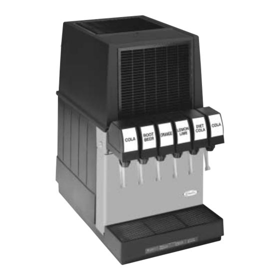
- Page 5 ............. . LIST OF FIGURES FIGURE 1. VENTURE SIX-FLAVOR POST-MIX DISPENSER ....
-
Page 6: Safety Information
SAFETY INFORMATION Recognize Safety Information This is the safety-alert symbol. When you see this symbol on our machine or in this manual, be alert to the potentially of personal injury. Follow recommended precautions and safe operating practices. Understand Signal Words DANGER A signal word - DANGER, WARNING, OR CAUTION is used with the safety-alert symbol. - Page 8 THIS PAGE LEFT BLANK INTENTIONALLY 318832000...
-
Page 9: General Information
This section gives the Unit description, theory of operation, and design data for the four-, five-, and six-flavor Venture Post-Mix Dispensers (hereafter referred to as Units). This Unit must be installed and serviced by a qualified Service Person. This Unit contains no User serviceable parts. -
Page 10: Warranty Reference Information
(to be filled out by customer) Unit Part Number: Serial Number: Install Date: Local Authorized Service Center: FIGURE 1. VENTURE SIX-FLAVOR POST-MIX DISPENSER Table 1. Design Data CARBONATED UNITS: 60 HZ Unit: 1/3 HP refrigeration 115 V, 60 HZ (Requires a Remote Carbonator) Four Flavor... - Page 11 Table 1. Design Data (cont’ d) 50 HZ Unit: 1/3 HP refrigeration 230V, 50 HZ (Requires a Remote Carbonator) Four Flavor 497354XXX Five Flavor 497355XXX 497400XXX 498355XXX 498400XXX Six Flavor 497356XXX 497401XXX 498356XXX 1/4 HP refrigeration 230V 50 Hz w/built-in Carbonator Four Flavor 497404XXX Five Flavor...
-
Page 12: Theory Of Operation
Table 1. Design Data (cont’ d) Unit Water Inlet Pressure 25-30 PSI Unit Electrical Requirements See Unit Nameplate No. of No. of 12 Oz Dispens- No. of Drinks 40°F Drinks/ Or Below Valves (see NOTE) 1/3 HP=650 1/4 HP=252 1/3HP =520 1/4HP = 248 NOTE: Number of 12-oz drinks dispensed 40°F or below @ 75°F syrup and water inlet temperature and 75°F ambient. -
Page 13: Noncarbonated Units
Units With Built-In Cold Carbonators. (see Figure 3) The Unit was set up at the factory to dispense a still (noncarbonated) drink from No. 3 dispensing valve and car- bonated drinks from the remaining dispensing valves. No. 3 dispensing valve may be converted to also dis- pense a carbonated drink. -
Page 14: Figure 2. Flow Diagram
COOLING COILS (9) CARBONATED- WATER MANIFOLD NON- - CARBONATED PLAIN DRINK WATER CO2 CHECK VALVE CAPPED FITTING REMOTE CARBONATOR REGULATED CO2 SUPPLY DISPENSER DISPENSING VALVE (6) SYRUP SUPPLY (SYRUP TANKS OR BAG-IN-BOX SYSTEM) LINE LEGEND PLAIN WATER SYRUP FIGURE 2. FLOW DIAGRAM (SIX FLAVOR UNIT REQUIRING CONNECTION TO A REMOTE CARBONATOR) 318832000... -
Page 15: Figure 3. Flow Diagram
REGULATED CO2 SUPPLY DOUBLE LIQUID CO2 CHECK CHECK VALVE BUILT- - IN VALVE CARBONATOR COOLING COILS (9) WATER PUMP PLAIN WATER NON- - CARBONATED DRINK CAPPED CROSS FITTING DISPENSER DISPENSING VALVE (6) CARBONATED- WATER SYRUP SUPPLY MANIFOLD (SYRUP TANKS OR BAG-IN-BOX SYSTEM) LINE LEGEND PLAIN WATER... -
Page 16: Figure 4. Flow Diagram (Six-Flavor Non-Carbonated Unit)
PLAIN PLAIN WATER WATER COOLING COILS SUPPLY WATER MANIFOLD SYRUP COOLING COIL (5) DISPENSER SYRUP SUPPLY (SYRUP TANKS OR BAG-IN-BOX SYSTEM) LINE LEGEND PLAIN WATER SYRUP FIGURE 4. FLOW DIAGRAM (SIX-FLAVOR NON-CARBONATED UNIT) 318832000... -
Page 17: Installation
Request a written inspec- tion report from Claims Inspector to substantiate any necessary claim. File claim with the delivering carrier, not with IMI Cornelius Inc. 1. After Unit has been unpacked, remove shipping tape and other packing material. -
Page 18: Selecting Location
UNITS WITH 1/4 H.P. REFRIGERATION AND BUILT-IN COLD CARBONATOR Item Part No. Name 317659039 Drip Tray 317660000 Cup Rest 317792000 Line Outlet Plug 77070402 Fitting, Stainless Steel, 5/8-18 (2) 176017000 Swivel Nut, 7/16-20 311304000 Tapered Gasket, Black 77010400 Nipple, 7/16 Nut (for .265 Tube) 300200000 Tubing Clamp SELECTING LOCATION... -
Page 19: Placing Unit In Operating Position
PLACING UNIT IN OPERATING POSITION NOTE: Some of the Units are manufactured with water and syrup inlet lines that are to be routed to out- side of the Unit and be connected to water and syrup source lines. Some Units are also assembled at the factory not equipped with water and syrup inlet lines and require water and syrup source lines to be routed to inside of the Unit and be connected to labeled stainless-steel inlet tubes on front of the Unit. -
Page 20: Installation
2. Install DRIP TRAY in position on the Unit, then place CUP REST in drip tray. CONNECTING PLAIN WATER SOURCE LINE(S) TO UNIT NOTE: IMI Cornelius Inc. recommends that a water shutoff valve and water filter be installed in plain water inlet supply line. A Cornelius Water Filter (P/N 313860000) and Quick Disconnect Set (P/N 313867000) are recommended. -
Page 21: Connecting Carbonated Water Source Line To Unit
CAUTION: Check the minimum flow rate and maximum pressure of plain water inlet supply line. MINIMUM FLOW RATE MUST BE AT LEAST 100-GALLONS PER HOUR. If flow rate is less than 100-gallons per hour, starving of carbonator water pump will occur. Starving will allow water pump to overheat and will damage the pump. -
Page 22: Standard Unit Requiring Connection To A Remote Carbonator
WARNING: CO displaces oxygen. Strict attention must be observed in the prevention of (carbon dioxide) gas leaks in the entire CO and soft drink system. If a CO gas leak is suspected, particularly in a small area, immediately ventilate the contaminated area before attempting to repair the leak. -
Page 23: Unit Operation
2. Adjust syrup tanks system or bag-in-box syrup system syrup pumps secondary CO regulator as instructed in SERVICE AND MAINTENANCE section of this manual. 3. Sanitize all syrup systems as instructed in SERVICE AND MAINTENANCE section of this manual. 4. Install syrup tanks or bag-in-boxes containing syrup into syrup systems UNIT OPERATION BLEEDING SYRUP AND APPLICABLE PLAIN OR CARBONATED WATER SYSTEMS 1. -
Page 24: Figure 5. Inlet Supply Line Connections (Standard Unit)
DISPENSING VALVE RELEASE LATCH DISPENSING VALVE BLOCK LABELED UNIT INLET LINES *CAPPED TEE (CARBONATED WATER) * This CAPPED TEE is used when converting No. 3 dispensing valve from a still ( noncarbonated ) to a carbonated drink. Refer to TABLE OF CON- TENTS for conversion instructions. -
Page 25: Figure 6. Inlet Supply Line Connections
DISPENSING VALVE RELEASE LATCH DISPENSING VALVE BLOCK *CAPPED CROSS FITTING (CARBONATED WATER) LABELED UNIT INLET LINES * This CAPPED CROSS FITTING is used when converting No. 3 dispensing valve from a still ( noncarbonated ) to a carbonated drink. Refer to TABLE OF CONTENTS for con- version instructions. -
Page 26: Figure 7. Inlet Supply Line Connections (Noncarbonated Unit)
DISPENSING VALVE RELEASE LATCH DISPENSING VALVE BLOCK LABELED UNIT INLET LINES FIGURE 7. INLET SUPPLY LINE CONNECTIONS (NONCARBONATED UNIT) 318832000... -
Page 27: Operator' S Instructions
OPERATOR’ S INSTRUCTIONS This section covers operating controls, daily pre-operation check, Unit operation, adjustments, replenishing and syrup supplies, cleaning and sanitizing, checking drop-in refrigeration assembly condenser coil for restrictions, checking ice water bath, water pump yearly maintenance on Unit with built-in carbonator and peri- odic cleaning of CO gas check valves. -
Page 28: Unit Operation
2. Make sure there is a sufficient syrup supply. If not, replenish syrup supply as instructed. 3. Make sure the drip tray and the cup rest are clean and are properly installed on the Unit. UNIT OPERATION 1. Make sure the Unit dispensing valves keyed lock-out switch is in the “ ON”(vertical) position. 2. -
Page 29: Checking Ice Water Bath
CHECKING ICE WATER BATH A “ gurgle”heard from the Unit indicates the water level in the water tank is low and more water should be added to the tank for maximum product cooling. Water should be added to the water tank as instructed in the SER- VICE AND MAINTENANCE section of this manual. - Page 30 THIS PAGE LEFT BLANK INTENTIONALLY 318832000...
-
Page 31: Service And Maintenance
SERVICE AND MAINTENANCE This section describes service and maintenance procedures to be performed on the Unit. IMPORTANT: Only qualified personnel should service internal components or electrical wiring. WARNING: Disconnect electrical power to the Unit to prevent personal injury before attempting any internal maintenance. Only qualified personnel should service the internal components or electrical wiring. -
Page 32: Figure 8. Dispenser Components
WATER FILL HOLE PLUG CARBONATOR WATER PUMP POWER SWITCH DISPENSING VALVE LEVER DISPENSING VALVES KEYEd LOCK-OUT SWITCH FIGURE 8. DISPENSER COMPONENTS (UNIT WITH BUILT-IN CARBONATOR SHOWN) 318832000... -
Page 33: Adjusting Dispensing Valve Water Flow Rate
NOTE: To readjust CO regulator to a lower setting, loosen adjusting screw lock nut, then turn screw to the left (counterclockwise) until pressure gage reads 5-psi lower than new setting will be. Turn adjust- ing screw to the right (clockwise) until gage registers new setting, then tighten lock nut. Adjusting Carbonator CO Regulator UNIT REQUIRING CONNECTION TO A REMOTE CARBONATOR (see Figure 2) -
Page 34: Sanitizing Post-Mix Syrup Systems
5. Remove nozzle and syrup diffusers from the dispensing valves. Place nozzles and syrup diffusers in sani- tizing solution. 6. Wash the nozzles and syrup diffusers in sanitizing solution, then rinse them with potable water. 7. Re-install nozzles and syrup diffusers back on the dispensing valves. SANITIZING POST-MIX SYRUP SYSTEMS IMPORTANT: Only qualified Service Personnel should perform sanitizing procedure on the post-mix syrup systems. - Page 35 9. Flush detergent solution out of the syrup system and dispensing valve as follows: Place waste container under applicable dispensing valve. Activate the dispensing valve for one minute to purge all detergent solution and flush out the syrup system. Continue to activate the dispensing valve in cycles (“ ON”for 15-seconds, “ OFF” , then “ ON”for 15-seconds).
-
Page 36: Cleaning Drop-In Refrigeration Assembly Condenser Coil
Activate the dispensing valve for one minute to purge all sanitizing solution out of the syrup system and the dispensing valve. Continue to activate the dispensing valve in cycles (“ ON”for 15-seconds, “ OFF” , then “ ON”for 15-seconds). Repeat “ ON”and “ OFF”cycles for 15-cycles. 21. -
Page 37: Cleaning Water Tank
2. Remove Unit hood by loosening screw on top of hood, then lift hood straight up off Unit. 3. Remove plug from drop-in refrigeration assembly platform water fill hole (see Figure 8). 4. Using a flashlight, inspect ice water bath and ice bank for cleanliness. Ice water bath should be clear and ice bank free of foreign particles. -
Page 38: Carbonator Water Pump Yearly Maintenance Or After Water System Disruptions
CARBONATOR SENSOR LEADS FIGURE 9. WATER TANK (UNIT WITH BUILT-IN COLD CARBONATOR SHOWN) 12. Remove plug from drop-in refrigeration assembly platform water fill hole. 13. Fill water tank with clean water to top of stainless steel coils located in coil basket. USE LOW-MINERAL- CONTENT WATER WHERE A LOCAL WATER PROBLEM EXISTS. -
Page 39: Unit Connected To Remote Carbonator (Standard Unit)
UNIT CONNECTED TO REMOTE CARBONATOR (STANDARD UNIT) The remote carbonator water pump water inlet strainer screen and double liquid check valve must be inspected and cleaned at least once a year under normal circumstances and after any water system disruption (plumbing work, earthquake, etc.). -
Page 40: Figure 10. Water Strainer Screen And Double Liquid Check
WATER LINE TO TANK DOUBLE LIQUID CHECK VALVE WHITE TAPERED GASKET SAFETY THERMOSTAT ELBOW (P/N 318040000) PUMP TO MOTOR COUPLING WATER PUMP WATER STRAINER SCREEN (P/N 315348000) O-RING (P/N 315349000) SCREEN RETAINER FIGURE 10. WATER STRAINER SCREEN AND DOUBLE LIQUID CHECK VALVE *INSTALL NEW BALL SEAT AT EACH SERVICING INDEX PART... -
Page 41: 3 Dispensing Valve Conversion From Still To Carbonated Drink
3. Disassemble each check valve as shown in Figure 11. 4. Wipe each part with clean lint-free cloth. Inspect each part, especially the ball for burrs, nicks, corrosion, deterioration, and other damage. Discard ball seat and any damaged or suspicious parts and replace with new parts during reassembly. -
Page 42: Unit With Built-In Cold Carbonator
7. Plug remote carbonator power cord into electrical outlet. 8. Open No. 3 dispensing valve and dispense until carbonated water is dispensed. UNIT WITH BUILT-IN COLD CARBONATOR One of the Unit plain water inlet lines is intended for connection to a plain water source to dispense a still (non- carbonated) drink from No. -
Page 43: Replenishing Syrup Supply
1. Fully close (clockwise) CO cylinder main shutoff valve. 2. Slowly loosen primary CO regulator assembly coupling nut allowing CO pressure to escape, then remove regulator assembly from empty CO cylinder. 3. Unfasten safety chain and remove empty CO cylinder. WARNING: To avoid personal injury and/or property damage, always secure CO cylinder in upright position with safety chain to prevent it from falling over. -
Page 44: Figure 12. Co2 Gas Check Valve Assembly
*QUAD RING 183294000 BALL 183296000 SPRING 183297000 RETAINER 183298000 BODY 183295000 *Quad ring seal must be replaced each time check valve is serviced. FIGURE 12. CO GAS CHECK VALVE ASSEMBLY THE GERMAN ICE BANK CONTROL IS FOR INTERNATIONAL USE ONLY. FIGURE 13. -
Page 45: Figure 14. Wiring Diagram (60 Hz Unit With 1/3 H.p. Refrigeration Assembly)
318832000... -
Page 46: Figure 15. Wiring Diagram (50 Hz Unit With 1/3 H.p. Refrigeration Assembly)
318832000... -
Page 47: Figure 16. Wiring Diagram (60 Hz Unit With 1/4 H.p. Refrigeration Assembly And Built-In Cold Carbonator)
318832000... -
Page 48: Figure 17. Wiring Diagram (50 Hz Unit With 1/4 H.p. Refrigeration Assembly And Built-In Cold Carbonator)
318832000... -
Page 49: Troubleshooting
TROUBLESHOOTING IMPORTANT: Only qualified personnel should service internal components or electrical wiring. WARNING: If repairs are to be made to a product system, remove quick disconnects from the applicable product tank, then relieve the system pressure before proceeding. If repairs are to be made to the CO system, stop dispensing, shut off the CO supply, then relieve the... -
Page 50: Adjustment Of Dispensing Valve Syrup Flow Control Does Not Decrease To Desired Water-To-Syrup " Ratio
STANDARD UNIT (REQUIRES CONNECTION TO A REMOTE CARBONATOR) CONT’ D Trouble Probable Cause Remedy ADJUSTMENT OF Dirty or inoperative dispensing Disassemble and clean DISPENSING VALVE SYRUP valve syrup flow control. dispensing valve syrup flow FLOW CONTROL DOES NOT control. DECREASE TO DESIRED WATER-TO-SYRUP “... -
Page 51: No Product Dispensed
STANDARD UNIT (REMOTE REQUIRES CONNECTION TO A REMOTE CARBONATOR) CONT’ D Trouble Probable Cause Remedy DISPENSED PRODUCT Tapered gasket inside Replace tapered gasket. Make PRODUCES FOAM AS IT carbonated water line swivel sure it is properly seated. LEAVES DISPENSING VALVE. nut connector distorted (cont’... -
Page 52: Unit With Built-In Cold Carbonator
UNIT WITH BUILT-IN COLD CARBONATOR Trouble Probable Cause Remedy WATER-TO-SYRUP “ RATIO” Dispensing valve syrup flow Adjust Water-to-Syrup “ Ratio”as TOO LOW OR TOO HIGH control not properly adjusted. instructed. Syrup Tanks System. Adjust CO regulator for syrup gas pressure to syrup tanks as instructed. -
Page 53: Dispensed Product Comes Out Of Dispensing Valve Clear
UNIT WITH BUILT-IN COLD CARBONATOR (CONT’ D) Trouble Probable Cause Remedy DISPENSED PRODUCT Oil film or soap scum in cups Use clean cups or glasses. COMES OUT OF or glasses. DISPENSING VALVE CLEAR BUT FOAMS IN CUP OR GLASS. Ice used for finished drink is Do not use ice directly from subcooled. -
Page 54: Only Carbonated Water Dispensed
UNIT WITH BUILT-IN COLD CARBONATOR (CONT’ D) Trouble Probable Cause Remedy NO PRODUCT DISPENSED No electrical power to Unit. Plug in Unit power cord or check FROM ALL DISPENSING for blown power fuse or tripped VALVES. (cont’ d) circuit breaker. Inoperative power switch (if Replace power switch. -
Page 55: Noncarbonated Unit
NONCARBONATED UNIT Trouble Probable Cause Remedy WATER-TO-SYRUP “ RATIO” Dispensing valve syrup flow Adjust Water-to-Syrup “ Ratio”as TOO LOW OR TOO HIGH control not properly adjusted. instructed. Syrup Tanks System. Adjust syrup tanks CO regulator gas pressure to syrup as instructed. tanks insufficient to push syrup out of tanks. -
Page 56: Dispensed Product Produces Foam As It Leaves
NON-CARBONATED UNIT (CONT’ D) Trouble Probable Cause Remedy DISPENSED PRODUCT Recovery rate of refrigeration Allow ice bank to recover. PRODUCES FOAM AS IT unit exceeded, ice bank LEAVES DISPENSING VALVE. depleted. CAUTION: The drop-in refrigeration assembly condenser coil must be periodically cleaned. -
Page 57: Compressor Operates Continuously But Does Not Form
REFRIGERATION SYSTEM (CONT’ D) Trouble Probable Cause Remedy COMPRESSOR DOES NOT No power source (blown fuse Replace fuse or reset circuit OPERATE. (cont’ d) or tripped circuit breaker). breaker. (NOTE: Fuse or circuit breaker are not part of unit). Inoperative Unit power switch Replace power switch or plug Unit (if applicable) or power cord power cord into electrical outlet. - Page 58 REFRIGERATION SYSTEM (CONT’ D) Trouble Probable Cause Remedy AGITATOR MOTOR NOT No power source (blown fuse Replace fuse or reset circuit OPERATING. (cont’ d) or tripped circuit breaker). breaker. (NOTE: Fuse or circuit breaker are not part of Unit). Agitator motor propeller Remove obstruction.
- Page 59 IMI Cornelius Inc. warrants that all equipment and parts are free from defects in material and workmanship un- der normal use and service. For a copy of the warranty applicable to your Cornelius, Remcor or Wilshire prod- uct, in your country, please write, fax or telephone the IMI Cornelius office nearest you. Please provide the equipment model number, serial number and the date of purchase.
- Page 61 IMI CORNELIUS INC. CORPORATE HEADQUARTERS: One Cornelius Place Anoka, Minnesota 55303-6234 (612) 421-6120 (800) 238-3600...
Need help?
Do you have a question about the VENTURE and is the answer not in the manual?
Questions and answers