Cornelius ABS 2.0 Service Manual
Hide thumbs
Also See for ABS 2.0:
- Service manual (68 pages) ,
- Installation manual (66 pages) ,
- Operator's manual (64 pages)

Related Manuals for Cornelius ABS 2.0


Summary of Contents for Cornelius ABS 2.0
- Page 1 ABS 2.0 Service Manual Release Date: Publication Number: 621058590SER Revision Date: 1 February , 2019 Revision: 3...
- Page 2 Commercial Warranty. Cornelius will not be responsible for any repair, replacement or other service required by or loss or damage resulting from any of the following occurrences, including but not limited to, (1) other than normal and proper use and normal...
-
Page 3: Table Of Contents
Introduction to Abs 2.0 Programming ........ - Page 4 Brand Mapping Explanation ........... . 34 Mapping –...
- Page 5 Mechanical Issues ............50 Beverage / Ice related Issues: .
-
Page 7: Safety Instructions
ABS 2.0 Service Manual SAFETY INSTRUCTIONS OLLOW AFETY NSTRUCTIONS Safety Overview • Read and follow ALL SAFETY INSTRUCTIONS in this manual and any warning/caution labels on the unit (decals, labels or laminated cards). • Read and understand ALL applicable OSHA (Occupational Safety and Health Administration) safety regulations before operating this unit. -
Page 8: Safety Precautions
ABS 2.0 Service Manual AFETY RECAUTIONS This unit has been specifically designed to provide protection against personal injury. To ensure continued protection observe the following: WARNING: Disconnect power to the unit before servicing following all lock out/tag out procedures established by the user. Verify all of the power is off to the unit before any work is performed. -
Page 9: General Information
When a bever- age is ordered from the P.O.S. register, the ABS 2.0 automatically drops a cup, fills it with ice and dispenses the cor- rect amount and type of any syrup-based beverage. The finished drink is then moved by the conveyor to the pick-up station and the drink description is displayed on the touchscreen. -
Page 10: Features
ABS 2.0 Service Manual EATURES Table 2. Product features Mounting type (leg/caster) 4 legs mounted UI interface type and size Two 7” touch screen display Number of flavors 8 brands Cup storage 6 cup dispenser Lid Storage 8 lid compartment... -
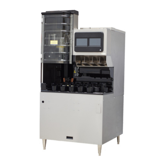
Page 11: Unit Drawing
ABS 2.0 Service Manual RAWING Figure 1. © 2019, Cornelius Inc. - 5 - Publication Number: 621058590SER... -
Page 12: E-Box Configuration
ABS 2.0 Service Manual E-BOX CONFIGURATION WARNING: Disconnect power to the unit before accessing the E-box. 30V DC Power Supply for Valve Bank. AC Power Inlet 3A-30V 4A-24V 4A-12V Figure 2. 12V DC 24V DC POWER SUPPLY POWER SUPPLY 1. Valve bank MFV board. -
Page 13: Conveyor Assembly / Splash Panel Removal
ABS 2.0 Service Manual CONVEYOR ASSEMBLY / SPLASH PANEL REMOVAL ONVEYOR SSEMBLY EMOVAL Table 3. Step Action Select manual button from start screen as shown Figure 3. Figure 3. Remove conveyor belt cover by removing the 3 thumb screw. Figure 4. -
Page 14: Splash Panel Removal
ABS 2.0 Service Manual PLASH ANEL EMOVAL Table 4. Step Action Open turret door (optional remove turret assembly) and remove the five screws holding the splash panel, as shown in Figure 7 and pull the panel forward and down to remove it. -
Page 15: Nozzle Diffuser Removal
ABS 2.0 Service Manual NOZZLE DIFFUSER REMOVAL NOTE: Diffuser cleaning or sanitizing is recommended twice weekly. Table 5. Step Action Turn nozzle clockwise (left), Than pull down, the diffuser will stay in position (it is keyed only, fits one way). - Page 16 ABS 2.0 Service Manual Step Action Line up the locating notches on inner circle of both the Seal and Diffuser. Push the Sili- cone Seal into the Diffuser until it sits flat. Figure 13. This side up – you should be able to feel the raised edges of the seal holes when you re- insert into nozzle.
- Page 17 ABS 2.0 Service Manual Step Action The Nozzle should sit on an angle. It should sit even with the unit Figure 18. If the Nozzle is installed on an angle, it is Incorrectly installed. An incorrectly installed nozzle will have decreased performance (dripping, excess carryover, etc).
-
Page 18: Multi-Flavor Valve Configuration
ABS 2.0 Service Manual MULTI-FLAVOR VALVE CONFIGURATION WARNING: Disconnect power to the unit before accessing the MFV valve. Table 6. Step Action Back-block layout behind each valve bank. Figure 20. MFV Valve Module placed on the back-block. Figure 21. Press the top snap (Dovetail) of back-block towards down as indicated in Figure 22. -
Page 19: Disassembly Of An Mfv Valve Module
ABS 2.0 Service Manual MFV V ISASSEMBLY ALVE ODULE Table 7. Step Action Once the valve module is removed, pull the locking clip upwards and remove. Figure 24. Pull up and rotate valve upwards of bracket to remove from the module. -
Page 20: Reassembly Of Mfv Valve
ABS 2.0 Service Manual MFV V EASSEMBLY OF ALVE Table 8. Step Action Place valve into the valve carrier. NOTE: Use only Dow III or equivalent on all o-rings Figure 27. Start the solenoid at a 45 deg. angle and... - Page 21 ABS 2.0 Service Manual Step Action The valve is back in position and ready to insert stainless steel locking clip. Figure 30. • Place valve on the backblock. (make sure wires are not pinched) • Push down on dovetail to lock valve.
-
Page 22: Ice Chute Removal
ABS 2.0 Service Manual ICE CHUTE REMOVAL Table 9. Step Action Select manual button from start screen Figure 33. Lift chute upward to release the locking tabs as shown in Figure 34 Figure 34. Then lift chute upwards to remove as shown in Figure 35. -
Page 23: Connecting Product To The Unit
ABS 2.0 Service Manual the U ONNECTING RODUCT TO The unit must have a product supply connected to each inlet on the valve. Refer to the “Plumbing Diagram” see on Refer on page54 for details of the hook-up. NOTE: All inlet connections are clearly marked with a label adjacent to the inlet connections.... -
Page 24: Syrup Line Cleaning & Sanitizing
ABS 2.0 Service Manual Syrup Line Cleaning & Sanitizing CAUTION: Only trained and qualified persons should perform these cleaning and sanitizing procedures.To sanitize the tubing and BIB connectors, perform the procedure in Table 10. Table 10 Step Action Quick Disconnect Remove all the quick disconnects from all the BIB containers. -
Page 25: Set Flow Rate And Valve Ratio
ABS 2.0 Service Manual ATE AND ALVE ATIO NOTE: Cold plate should have ice on it and should be cold. Remove the conveyor assembly to allow easy access to the area under the valve for the ratio cup. Table 11... -
Page 26: Adjusting Water Flow Rate
DJUSTING ATER Overview: The ABS 2.0 uses 2 MFV water valves for both carbonated water (CW1 & CW2) and plain water (PW1 & PW2). Each valve module has a high-flow orifice and a low-flow orifice. The high-flow orifice provides approximately 75% and the low-flow orifice provides approximately 25% of the total flowrate. During a beverage dispense, both valves are activated and together provide the total water flowrate required. -
Page 27: Set Overall Water Valve
ALVE Important: This is the step that adjusts the pour times of all beverages dispensed from the ABS 2.0. If this step is not completed, then drinks will either over- or under-pour depending on the flowrate adjustment of the valves... -
Page 28: Adjust The Syrup Ratio (Brand)
ABS 2.0 Service Manual Troubleshooting: • If drinks overfill, this means the dispense times are too high for the flowrate that the valves have been adjusted to. Repeat the above steps and increase volume entered. This will shorten the dispense time prevent overfilling. - Page 29 ABS 2.0 Service Manual U.S.A. FOLLOW THE PROCEDURE BELOW: 1. Hold the ratio cup water compartment below the valve and select the Plain Water button if adjusting a non- carbonated drink or the carbonated water button if adjusting a carbonated water drink.
-
Page 30: Cleaning Interior Surfaces
ABS 2.0 Service Manual LEANING NTERIOR URFACES As part of the monthly cleaning and sanitizing the hopper, perform the procedure in Table 14. CAUTION: When pouring sanitizing liquid into the hopper, do not exceed the rate of 1/2 gallon per minute. Pouring liquid into the hopper faster than the recommended rate could result in an overflow situation which may result in personal injury or damage to the equipment. - Page 31 ABS 2.0 Service Manual Table 14. Open the turret door and remove the ice chute cover from the unit. Figure 52. With a nylon bristle brush or sponge, clean the inside of the ice chute, gasket, and cover with sanitizing solution and rinse thoroughly to remove all traces of detergent.
-
Page 32: Initializing And Self Test
NITIALIZING Turn ON the ABS 2.0 unit at the ABS 2.0 ON/OFF switch located on the left top corner of the stand. During the power-up sequence the Self Test and Initializing messages will be displayed as each test is being made. When the tests are complete the final message will be displayed and will remain for 5 seconds before the unit is placed in the manual mode. -
Page 33: Auto Mode Operation
MANUAL button Figure 33. And the reverse is also true, when in MANUAL the ABS 2.0 can be switched to AUTO by pressing the AUTO button. When the ABS 2.0 is in the AUTO mode it is just that – Automatic. There are no settings to be made in this mode and no menus to access. -
Page 34: Clear The Pos Order Buffe
ABS 2.0 Service Manual LEAR RDER UFFE Table 15 Step Action Select the Order Queue from starting menu as shown in Figure 57. Figure 57. Press Delete for each order or Delete all button as shown in NOTE:Figure 58. Figure 58. -
Page 35: Manual Mode Operation
In the MANUAL mode, POS data is updated and ALARM messages are displayed. In MANUAL mode the highlight flashes to alert operator that the ABS 2.0 unit is in the MANUAL mode. While in the MANUAL mode, POS drink orders continue to be received and placed in the order buffer. -
Page 36: To Service
Default Settings/Restoring Settings The ABS 2.0 system is factory set to satisfy the majority of all installations. Do not make any adjustments until you are sure the factory settings will not satisfy the store requirements. Touch Panel Layout & Explanation... -
Page 37: Display Explanation
6. Alarm, cleaning due or past due. 7. Order - Current example. -L (Large), Regular (Ice type) -Order (ABS 2.0 = Semi Auto or Order Number) 8. Finished Drinks 1-6, left to right, Coke is Position one. 9. Flush - CW has flushed the Nozzle. -
Page 38: Entering The Technician Screen
ABS 2.0 Service Manual the T NTERING ECHNICIAN CREEN Table 16. Step Action 1. Select the Menu as shown in Figure 62. Figure 62. 3. Select the Technician Icon as shown Figure Figure 63. Close the Clear the 5. Enter 9876, then green arrow as shown... -
Page 39: Syrup Mapping (Brand)
ABS 2.0 Service Manual YRUP APPING BRAND Syrup Map The table below, shows all the brand names that are resident in the ABS 2.0 system. The shaded area is the default brands. U.S. Version as follows: Table 17. DEFAULT SETTINGS... -
Page 40: Brand Mapping Explanation
#2. Figure 66.Syrup Map Explanation 1 Drink List Create a drink list showing the exact position of each drink in the ABS 2.0 system give to GM or keep at the unit (Behind screen) Table 19. POS ID brand / Aust. -
Page 41: Mapping - Second Step
ABS 2.0 Service Manual Mapping – Second Step Table 20 Step Action From unit setup Menu select the Map Brands to Valves as shown in Figure 67. Figure 67. Brand mapping menu as shown in Figure Figure 68. Select the Valve’s as shown in Figure 69. -
Page 42: Drink List
ABS 2.0 Service Manual Table 20 Select the brand to assign the valve by scroll the brand’s using of up/down arrow as shown in Figure 70. Figure 70. Save the Mapping and back to home or previous menu Figure 71. -
Page 43: Adjusting Water Flow Rate
DJUSTING ATER Overview: The ABS 2.0 uses 2 MFV water valves for both carbonated water (CW1 & CW2) and plain water (PW1 & PW2). Each valve module has a high-flow orifice and a low-flow orifice. The high-flow orifice provides approximately 75% and the low-flow orifice provides approximately 25% of the total flowrate. During a beverage dispense, both valves are activated and together provide the total water flowrate required. -
Page 44: Adjustment Ice
ABS 2.0 Service Manual DJUSTMENT The conveyor assembly must be installed before beginning this procedure. Table 22 Place the measuring cup under the ice dispenser.Select the “Ice Dispense Calibration” Icon from the Unit setup menu as shown in Figure 73. -
Page 45: Alarm And Warning Messages
ABS 2.0 Service Manual and W LARM ARNING ESSAGES Follow the steps to alarm logging Table 23 Step Action From the staring page select the Menu page Icon as shown in Figure 77. Figure 77. From the menu page select “Alarm Logging”... -
Page 46: Cup Conveyor
ABS 2.0 Service Manual CUP CONVEYOR ESCRIPTION PERATION The conveyor is controlled by the Motion Control Board. When a drink order is placed at the POS the correct cup is pulled and placed into the conveyor. The conveyor is then rotated clockwise by the gear motor to move the cup to the ice drop position based on the following information: •... -
Page 47: Cup Serve Point "A" Sensor
If, for example, there were cups at Cup Serve Positions; “A” and “B”, and the cup at Point “A” was removed the conveyor would rotate one space until the cup that was at Point “B” moves to Point “A”, then the ABS 2.0 would be stopped again. -
Page 48: Conveyor Drive Alignment
ABS 2.0 Service Manual ONVEYOR RIVE LIGNMENT When installing the conveyor the conveyor belt may be rotated to align the Drive Pin and the Drive Socket. The Drive Pin on the conveyor must engage the Drive Socket on the gear motor or the conveyor is not properly installed and will not operate. -
Page 49: Cup Picker
ESCRIPTION PERATION The Cup Puller is activated by a command from the POS to the ABS 2.0. When a drink order is placed at the POS, the correct cup is pulled and placed into the conveyor. The cup puller consists of, two cup grabber arms actuated by a pneumatic cylinder, an elevating mechanism operated by a pneumatic cylinder, and two guide rods. -
Page 50: Empty Cup Tube Sensor
CAUTION: Do Not attempt any repair until the ABS 2.0 unit has been shut down and the air/CO2 has been shut OFF. Serious injury could occur if the cup grabber activates during repair. of C... -
Page 51: Cup Turret System
24” drive shaft, shrouded with a protective sleeve. The cup turret is activated by a command from the POS to the ABS 2.0. The cup turret rotates so that the correct cup size is at the cup drop position. The cup is then pulled and placed into the conveyor. -
Page 52: Turret Drive Assembly
& M URRET OTOR The gear box and motor are replaceable and are accessible from top side under the black cover of the ABS 2.0. Four bolts attach them to the Gear/Motor bracket. NCODER The alignment disk, attached with three screws to the shaft coupler, interfaces with the turret position sensor and notifies the Motion Control Board of which cup tube is at the extract position. -
Page 53: Ice Chute Assembly
ABS 2.0 Service Manual ICE CHUTE ASSEMBLY ESCRIPTION The ice gate is a pneumatically operated “gate” that is controlled by the Beverage Interface Board. The time the gate is open is very precise and determines the portion of ice dispensed. The gate opens and closes under pneumatic pressure(35psi). -
Page 54: Dispensing Valve
ABS 2.0 Service Manual DISPENSING VALVE ALVE ESCRIPTION The dispensing valve is located behind the touch panel and is made up of 5 blocks, each containing 2 solenoids, 2 flow controls and 2 shut-offs. The blocks are permanently manifolded together to supply a single outlet. -
Page 55: Troubleshooting
ABS 2.0 Service Manual TROUBLESHOOTING WARNING: Only trained and certified electrical, plumbing and refrigeration technicians should service this unit. ALL WIRING AND PLUMBING MUST CONFORM TO NATIONAL AND LOCAL CODES. FAILURE TO COMPLY COULD RESULT IN SERIOUS INJURY, DEATH OR EQUIPMENT DAMAGE. -
Page 56: Mechanical Issues
ABS 2.0 Service Manual ECHANICAL SSUES Table 26 Message Explanation Correction Remove all cups from the conveyor Cup(s) is jammed in the conveyor at cup holders at the Extract Position the cup extraction position and the before pressing the ENTER button. -
Page 57: Beverage / Ice Related Issues
ABS 2.0 Service Manual EVERAGE CE RELATED SSUES Table 27 Message Explanation Correction A. Ice Chute not installed correctly. Reinstall Ice Chute. B. Bad solenoid valve. Call for service. C. Plugged orifice. NO ICE DISPENSE Call for service. D. No / Low CO Call for service. -
Page 58: Pos Related Issues
Make sure that the order in which the brands and size are the same in brand ABS UNIT IS Setup and size Setup in the Drink dispenser as it is on the ABS 2.0 System. DISPENSING THE Coca-Cola will provide the brand Position Guide for POS programming. -
Page 59: Wiring Diagram
ABS 2.0 Service Manual WIRING DIAGRAM 12V PSU 620069957 24V PSU 620069958 RE D W Valve 1 W HT W Valve 2 W Valve 3 W Valve 4 RE D S Valve 1 S Valve 2 W HT S Valve 3... -
Page 60: Plumbing Diagram
ABS 2.0 Service Manual PLUMBING DIAGRAM AIR/CO2 FILTER & REGULATOR UNIT 560000391 52PSI PICKER POSITIONS 2A OFF 2B ON 3B ON MIDDLE: 2A ON 2B OFF 3B ON DOWN: 2A ON 2B OFF 3B OFF DRAIN GRPR A GRPR B... - Page 61 ABS 2.0 Service Manual © 2019, Cornelius Inc. - 55 - Publication Number: 621058590SER...
- Page 62 ABS 2.0 Service Manual Publication Number: 621058590SER - 56 - © 2019, Cornelius Inc.
- Page 64 Cornelius Inc. www.cornelius.com...
Need help?
Do you have a question about the ABS 2.0 and is the answer not in the manual?
Questions and answers
Managers code from the menu option
The manager's code for the Cornelius ABS 2.0 is 1234.
This answer is automatically generated