
Subscribe to Our Youtube Channel
Related Manuals for Cornelius VIPER


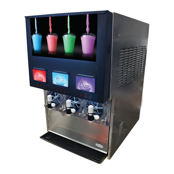
Summary of Contents for Cornelius VIPER
- Page 1 VIPER (E) 3 FLAVOR LOW OVERRUN Service Manual Release Date: May 10, 2016 Publication Number: 621360241LOEWSE Revision: A Visit the Cornelius web site at www.cornelius.com for all your Literature needs.
-
Page 2: Contact Information
Commercial Warranty. Cornelius will not be responsible for any repair, replacement or other service required by or loss or damage resulting from any of the following occurrences, including but not limited to, (1) other than normal and proper use and normal... - Page 3 TABLE OF CONTENTS Safety Instructions ............. . . 1 Read and Follow ALL Safety Instructions .
- Page 4 Clock Setup Menu ............17 Setting the Clock .
- Page 5 Monthly Maintenance ............37 Cleaning Air Filter .
-
Page 7: Safety Instructions
Viper Low overrun Service Manual SAFETY INSTRUCTIONS ALL S EAD AND OLLOW AFETY NSTRUCTIONS Safety Overview • Read and follow ALL SAFETY INSTRUCTIONS in this manual and any warning/caution labels on the unit (decals, labels or laminated cards). • Read and understand ALL applicable OSHA (Occupational Safety and Health Administration) safety reg- ulations before operating this unit. - Page 8 Viper Low overrun Service Manual UALIFIED ERVICE ERSONNEL WARNING: Only trained and certified electrical, plumbing and refrigeration technicians should service this unit. ALL WIRING AND PLUMBING MUST CONFORM TO NATIONAL AND LOCAL CODES. FAILURE TO COMPLY COULD RESULT IN SERIOUS INJURY, DEATH OR EQUIPMENT DAMAGE.
-
Page 9: Introduction
This manual is designed as a guide to the technician in maintaining and servicing the Viper system. The Viper system is simple in design and has built-in features and diagnostic controls to help the service technician quickly and accurately service the machine. -
Page 10: Dispensed Product Conditions
Viper Low overrun Service Manual DISPENSED PRODUCT CONDITIONS VERRUN PPLIED TO ARBONATED EVERAGES VERRUN EFINITION Overrun is defined as product expansion that takes place in the frozen carbonated drink. It is caused primarily by gas breakout and secondarily by freezing. -
Page 11: System Overview
The refrigeration system schematic is shown in Figure 2. It shows the basic configuration for the Viper refrigeration system. The wiring diagram of the 3-Barrel Viper unit is shown in Figure 3. This diagram shows the details of the electrical connections in the unit. - Page 12 Viper Low overrun Service Manual Figure 2. Low overrun Viper System 3-Barrel Refrigeration Schematic Publication Number: 621360241LOEWSE - 6 - © 2016, Cornelius Inc.
- Page 13 Viper Low overrun Service Manual Figure 3. Low overrun Viper 3-Barrel Wiring Diagram © 2016, Cornelius Inc - 7 - Publication Number: 621360241LOEWSE...
- Page 14 Viper Low overrun Service Manual An overall schematic of the three delivery systems contained in the unit are shown in Figure 5. The CO system is on top, the water system is in the middle and the syrup system is at the bottom of the diagram. The CO system interacts with both the water and syrup systems.
- Page 15 Viper Low overrun Service Manual Table 1 provides guidelines for machine settings based on general syrup type. Several factors, including syrup for- mulation, level of citric acids, etc, will impact settings. These settings are to provide initial adjustments to achieve product overruns in the 80-120% range.
-
Page 16: Water System
Viper Low overrun Service Manual Figure 5. 3-Barrel System Schematic Water System Incoming water flows to a water pressure regulator that is preset to 30 psig. It flows through the water booster pump, to the regulator and through a sold-out switch. -
Page 17: Syrup System
The control system is set up by the service provider to perform the tasks necessary to keep the Viper unit operating correctly. In addition to controlling the unit, the control system keeps track of the diagnostic information used when adjusting and/or repairing the machine. -
Page 18: Control Panel Buttons
Viper Low overrun Service Manual Control Panel Buttons The second area are the buttons and arrows located across the bottom and on the right side of the control panel. There are up to five buttons and four directional arrows that may be used on a screen to activate and control vari- ous the functions of the system. -
Page 19: System Menus
Viper Low overrun Service Manual ONTROL ANEL ESCRIPTIONS The following section describes the information displayed on each control panel menu and the interactions and set- tings that are controlled by that menu. System Menus The system menu structure allows the user to control the unit through the control panel. Operational settings, optional parameters, troubleshooting and error information are controlled through this menu system. -
Page 20: Unit Data Menu
Viper Low overrun Service Manual When the Select menu is displayed, the Unit Data is highlighted. To access the Unit Data menu, press the GO but- ton. Refer to Table 3, the Select menu, for button functions. Table 3. Button... - Page 21 Viper Low overrun Service Manual Table 5. Error Type Description A Limp error is an error that doesn’t prevent the unit from operating, but lim- Limp its functionality. The possible messages from the control system and a description of the errors are shown in Table 6. The button functions are described in Table 7.
-
Page 22: Error Log Menu
Viper Low overrun Service Manual Table 6. Displayed Action Type Description Message Motor stalled. A two minute defrost and two MOTOR STALL Barrel retries are allowed, then the message is dis- played, METER FAIL Barrel Metering chip is nonresponsive. Barrel viscosity is too high. Motor cannot rotate. -
Page 23: Setup Menu
Viper Low overrun Service Manual ERROR ERROR NUMBER #3 COMM FAIL OCCUR: 2:44 PM 3/04/08 12:51P CLEAR: 2:52 PM MAR 04 3/04/08 BACK Figure 12. Error Log Screen Table 8. Button Description BACK Returns the display to the Select menu... -
Page 24: Setting The Clock
Viper Low overrun Service Manual TIME: 11:00 AM CLOCK DATE: 01/01/00 SETUP 12:51P MAR 04 BACK CLOCK Figure 14. Clock Setup Screen Table 10. Button Description BACK Returns the display to the Select menu CLOCK Highlighted to indicate that the Clock menu is displayed... -
Page 25: Setting Daylight Savings Time
Viper Low overrun Service Manual Table 12. Step Action Procedure Use the + or - buttons at the bottom of the display to Set correct year set the correct year. Setting Daylight Savings Time Once the date and time are set properly, daylight savings time settings can be done. The Daylight Savings Time menu is shown in Figure 15. -
Page 26: Events Setup Menu
Viper Low overrun Service Manual Events Setup Menu The Events Setup menu, shown in Figure 16, allows the user to set sleep periods for the unit and to lock out the defrost cycle during peak busy times. Sleep periods and defrost lockouts may be programmed for any day of the week or for all days of the week, depending on business requirements. -
Page 27: Setting Defrost Lockout
Viper Low overrun Service Manual Table 16. Step Action Procedure Use the left and right arrows to select the hour field Set hour field and press the + or - buttons to change the hour. Use the left and right arrows to select the minute... -
Page 28: Viscosity Setup Menu
Viper Low overrun Service Manual Viscosity Setup Menu The viscosity maintained in the freeze barrels depends on the type of product being served. Some products are served best at a higher viscosity, while others require a lower viscosity for best quality. The Viscosity menu, shown in Figure 17, allows the user to adjust the viscosity in each barrel to the optimum setting for each type of syrup. -
Page 29: Option Setup Menu
Viper Low overrun Service Manual Table 19. Step Action Procedure Set CO Pulse valve From the Setup screen (Figure 13), select the CO2 duration Setup screen, shown in Figure 18. Use the Up and Down arrows to highlight the Select barrel desired barrel. -
Page 30: Setting The Date Format
Viper Low overrun Service Manual Setting the Date Format The date format can be displayed in either United States or European format. To display U.S. date format, press the USA button. This displays the date in mm/dd/yy format. Press the EURO button to display the date in dd/mm/yy for- mat. -
Page 31: Purging A Barrel
Viper Low overrun Service Manual BARREL #1 PURGE #2 OFF MAINT 12:51P MAR 04 BACK PURGE FILL SPIN Figure 21. Barrel Maintenance Screen Purging a Barrel Table 21. Step Action Procedure From the Select menu (Figure 20), open the Barrel Purge a barrel Maintenance menu, shown in Figure 21. -
Page 32: Run The Barrel Motor
Viper Low overrun Service Manual Run the Barrel Motor Table 23. Step Action Procedure From the Setup menu (Figure 20), open the Barrel Run a barrel Maintenance menu, shown in Figure 21. Use the Up and Down arrows to highlight the desired... -
Page 33: Totals Menu
Viper Low overrun Service Manual POS LIGHTING MANUAL COMPRESSOR #1 DIAG HOT GAS SOL #1 PRODUCT SOL #1 12:51P CO2 VALVE #1 MAR 04 LLS VALVE #1 BACK Figure 22. Manual Diagnostic Screen The items shown in Table 25 are for the first barrel in the unit only. The list includes additional components with their related barrel number, i.e. -
Page 34: Brix Setup Menu
Viper Low overrun Service Manual POWER ON 00079:34 TOTALS SLEEP 00034:21 SYSTEM ERROR 00003:45 COMP RUN #1 00006:53 12:51P COMP CYCLES #1 0000012 MAR 04 BARREL REFG #1 00006:54 BACK Figure 23. Totals Screen Table 26. Display Value Description Shows how long the machine has been pow-... - Page 35 Viper Low overrun Service Manual Table 27. Step Action Procedure Turn product supply valve to the 180 degree (BRIX) Set product supply valve position for the barrel you are testing. (See Figure Access BRIX menu Press MENU. Then press the SETUP button.
- Page 36 Viper Low overrun Service Manual Splash Panel Retaining Screws Figure 25. Splash Panel Mounting Screws Product Product Product Supply Supply Flow Flow Flow Supply Valve Valve Valve Controls Controls Controls Barrel 1 Barrel 2 Barrel 3 Barrel 1 Barrel 2 Barrel 3 Valves shown in BARREL position w/ Splash Panel &...
-
Page 37: Motor Setup Menu
Viper Low overrun Service Manual Motor Setup Menu Motor setup is initially done at the factory and does not need to be changed unless a barrel motor or barrel compo- nents are replaced, adjusted or removed and reinstalled. This menu allows you to select different motor types for each barrel in the unit and run the calibration procedure on that motor. -
Page 38: Calibrating A Motor
Viper Low overrun Service Manual Calibrating a Motor Calibration of motors is typically required when a motor or any associated barrel components (i.e., scraper blades, seal, faceplate, etc.) is removed or replaced. Calibration establishes a new baseline for the motor assembly. This allows the system to determine proper viscosity settings for the new motor. -
Page 39: Security
Viper Low overrun Service Manual SYSTEM # OF BARRELS # OF COMPRESSOR 1 SECURITY CMP #1 SENSORS BOTH 12:51P CMP #X SENSORS LOW MAR 04 BACK Figure 29. System Screen Table 32. Display Description This selection shows the number of barrels in the system and # OF BARRELS allows the user to change the quantity. - Page 40 Viper Low overrun Service Manual SYSTEM # OF BARRELS # OF COMPRESSOR 1 SECURITY CMP #1 SENSORS BOTH 12:51P MAR 04 BACK NONE HIGH BOTH Figure 30. System Screen When the pressure sensors selection is highlighted, pressing the NONE button removes the pressure readings from the Unit Data screen, shown in Figure 31.
-
Page 41: Dispensed Product Throughput
Programmed Defrost Scheduling The control system in the Viper system includes a function to automatically defrost product in the barrel at programmed intervals based on the viscosity of the product. Programmed defrosts are scheduled frequently to ensure that product quality within the barrel is maintained. -
Page 42: Viscosity Setting
Cornelius recommends that the viscosity settings be set at the lowest possible setting to achieve the desired drink qual- ity. In most typical installations using a sugar-based syrup, acceptable drink quality can be achieved by programmed vis- cosity settings in the range of 3-5 for Viper. -
Page 43: Summary
PREVENTATIVE MAINTENANCE UMMARY There are no daily maintenance procedures required on the Viper unit other than normal cleanup of spills or over- spray and emptying the drip tray. Normal equipment maintenance intervals are listed in Table 36. It is recom- mended that a preventative maintenance procedure be performed every six (6) months. -
Page 44: Semi-Annual Maintenance
Viper Low overrun Service Manual Table 37. Step Action Open the merchandiser Remove the filter, shown in Figure 32, by grasping the two tabs and sliding it straight out the front of the unit. Wash the filter with clean water. Shake out the excess water. -
Page 45: Cleaning The Syrup Connections
Viper Low overrun Service Manual Table 38. Step Action Re-install the faceplate and replace the four (4) mounting nuts. Hand tighten the nuts until the faceplate makes contact with the gasket, then use a wrench to tighten the nuts an additional 1/4 turn. Be careful not to over tighten the nuts or cracking of the faceplate may result. -
Page 46: Sanitizing The System
Viper Low overrun Service Manual Table 40. Step Action Defrost freeze cylinders, shut unit down, disconnect electrical power from Unit. Perform the procedure in Table 41 to empty the barrels. Remove the hex nuts and flat washers securing the faceplate to the freeze barrel, then remove the faceplate from the barrel. -
Page 47: Emptying A Barrel
Viper Low overrun Service Manual Emptying a Barrel To empty the barrel, perform the procedure in Table 41. Table 41. Step Action From the Barrel Status menu, press the DFRST button. When the barrel is defrosted, go to the Maintenance menu. If the security fea- ture is active, access the Maintenance menu by pressing and holding the far left and right buttons simultaneously for approximately five seconds. -
Page 48: Sanitizing The Barrel
Viper Low overrun Service Manual Table 42. Step Action Perform inspection and replacement of scraper blades. See “Inspecting and Replacing Scraper Blades” on page 38. Perform a leak test on the barrel. See “Motor Seal Leak Test” on page 46. - Page 49 Viper Low overrun Service Manual Table 44. Step Action Turn the Product/BRIX valve to the Product position. Manually open the manual water flow valve to start filling the barrel with wash water. At the same time, open the faceplate relief valve until water comes out.
-
Page 50: Installing A New Seal
Viper Low overrun Service Manual COMPONENT REPLACEMENT The following are procedures for servicing the major components of the Viper system. ARREL OTOR EPLACEMENT The barrel motor seal is typically replaced during the semi-annual preventative maintenance procedure. The seal location is shown in Figure 34. - Page 51 Viper Low overrun Service Manual Table 46. Step Action Remove the old seal and the spacer (see Table 45). Remove the new seal from its packaging. Clean the spacer. Slide the spacer (with slots toward the motor housing) over the motor shaft.
- Page 52 Viper Low overrun Service Manual Seal Spacer Figure 36. Side View of Seal and Spacer on Motor Shaft OTOR After replacing the motor seal, it is advisable to test the seal under pressure before refilling the barrel with product. Perform the procedure in Table 47 to verify that the seal is installed properly and not leaking. When the seal passes the leak test, perform the motor calibration routine on page 32.
- Page 53 Viper Low overrun Service Manual Barrel Motor Mounting Bolts Foam Pack Figure 37. Side View of Motor Showing Two of the Four Mounting Bolts Table 48. Step Action Perform the procedure in Steps 1 through 8 of Table 45. Disconnect the motor from the circuit by unplugging the connector.
- Page 54 Viper Low overrun Service Manual Table 49. Step Action Remove the mounting screw from the base of the capacitor. Replace the capacitor. Reverse the procedure to install the new capacitor. Reconnect power to the unit. Refill the barrel with product. See “Filling a Barrel” on page 25.
- Page 55 Viper Low overrun Service Manual Mounting Pulse Valve Tie-Wrap Figure 40. Side View of CO Pulse Valves Pulse Valves Figure 41. Front View of CO Pulse Valves Table 51. Step Action Disconnect power from the unit. Disconnect the CO supply from the unit.
- Page 56 Viper Low overrun Service Manual Syrup Shutoff Valves & Solenoids Figure 42. View of Shutoff Solenoids w/ Access Panel Removed Table 52. Step Procedure Disconnect power from the unit. Disconnect and bleed the water and syrup lines to remove pressure from the system.
- Page 57 Remove the compressor and unsweat the discharge line. Reverse the procedure to install the new compressor. Replace the dryer. Evacuate the system and recharge it according to the Cornelius nameplate on the unit. Replace the side panels and rear cover.
- Page 58 Viper Low overrun Service Manual OLENOID EPLACEMENT The hot gas valves and solenoids, shown in Figure 45, are located near the center of the unit on the right and left sides. Whenever a hot gas valve and solenoid is replaced, the dryer should be replaced at the same time. Perform the procedure in Table 55 to replace the solenoid.
- Page 59 Viper Low overrun Service Manual Table 56. Step Action Disconnect power from the unit. Remove the side panels. Reclaim refrigerant from the system. Carefully unwrap the foam insulation from around the valve and solenoid. Remove the liquid line valve and solenoid.
- Page 60 Viper Low overrun Service Manual Water Pressure Switch Figure 48. View of Water Pressure Switch Table 58. Step Action Disconnect power from the unit. Remove the side panel from the unit. Turn off the water supply to the unit. Drain the water from the system.
-
Page 61: Software Compatibility
Figure 50. View of Control Board in E-Box Software Compatibility Low overrun software is not compatible with standard Viper software versions. When ordering replacement/service parts for any unit check the software version of the UI and IO boards and be sure to order the correct board. - Page 62 Viper Low overrun Service Manual The motor board is located in the E-Box, to the right of the control board. It is mounted to the panel on three (3) plastic mounting studs and a threaded standoff, shown in Figure 51. To replace the motor board, perform the procedure in Table 61.
-
Page 63: Troubleshooting
Viper Low overrun Service Manual TROUBLESHOOTING ROUBLESHOOTING THE YSTEM Problem Probable Cause Remedy Unit will not run. A. Unit not plugged in. A. Plug in unit. B. Circuit breaker. B. Reset/replace circuit breaker C. No power at L1 or L2 on contactor. - Page 64 Viper Low overrun Service Manual ROUBLESHOOTING RODUCT Problem Probable Cause Remedy Compressor not Running A. Barrel not in ON mode. A. Turn barrel to ON. B. No voltage to compressor. B. Check power at contactor L1, L2 - T1, T2.
- Page 66 Cornelius Inc. www.cornelius.com...
Need help?
Do you have a question about the VIPER and is the answer not in the manual?
Questions and answers