Cornelius IDC PRO 255 Installation Manual
Hide thumbs
Also See for IDC PRO 255:
- Service manual (50 pages) ,
- Operator's manual (46 pages) ,
- Installation instructions (2 pages)

Related Manuals for Cornelius IDC PRO 255


Summary of Contents for Cornelius IDC PRO 255
- Page 1 IDC PRO 255 Installation Manual Release Date: August 05, 2016 Publication Number: 621058578INS Revision Date: June 20, 2018 Revision: B Visit the Cornelius web site at www.cornelius-usa.com for all your Literature needs.
- Page 2 Commercial Warranty. Cornelius will not be responsible for any repair, replacement or other service required by or loss or damage resulting from any of the following occurrences, including but not limited to, (1) other than normal and proper use and normal...
-
Page 3: Table Of Contents
TABLE OF CONTENTS Safety Instructions..............1 Read and Follow ALL Safety Instructions . -
Page 4: Safety Instructions
IDC Pro 255 Installation Manual SAFETY INSTRUCTIONS ALL S EAD AND OLLOW AFETY NSTRUCTIONS Safety Overview • Read and follow ALL SAFETY INSTRUCTIONS in this manual and any warning/caution labels on the unit (decals, labels or laminated cards). • Read and understand ALL applicable OSHA (Occupational Safety and Health Administration) safety regu- lations and/or national and local codes before operating this unit. -
Page 5: Qualified Service Personnel
IDC Pro 255 Installation Manual UALIFIED ERVICE ERSONNEL WARNING: Only trained and certified electrical, plumbing and refrigeration technicians should service this unit. ALL WIRING AND PLUMBING MUST CONFORM TO NATIONAL AND LOCAL CODES. FAILURE TO COMPLY COULD RESULT IN SERIOUS INJURY, DEATH OR EQUIPMENT DAMAGE. - Page 6 IDC Pro 255 Installation Manual OISE EVEL This unit emits acoustical noise with an A-weighted sound pressure level no greater than 75dB, as measured in accordance with ED 60335-2-75. © 2016-2018, Cornelius Inc. - 3 - Publication Number: 621058578INS...
-
Page 7: System Overview
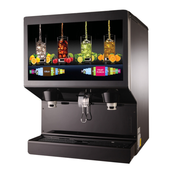
SYSTEM OVERVIEW The IDC PRO 255 unit solves your ice and beverage service needs in a sanitary, space saving, economical way. It is designed to be manually filled with ice from any remote ice making source. The unit distributes cubes (up to 1-1/4 inch in size), Cubelet and compressed (not flaked) ice. - Page 8 IDC Pro 255 Installation Manual Figure 1. © 2016-2018, Cornelius Inc. - 5 - Publication Number: 621058578INS...
-
Page 9: Installation
IDC Pro 255 Installation Manual INSTALLATION WARNING: Only trained and certified electrical, plumbing and refrigeration technicians should service this unit. ALL WIRING AND PLUMBING MUST CONFORM TO NATIONAL AND LOCAL CODES. FAILURE TO COMPLY COULD RESULT IN SERIOUS INJURY, DEATH OR EQUIPMENT DAMAGE. - Page 10 IDC Pro 255 Installation Manual NOTE: Cornelius Inc. recommends that a water shutoff valve and water filter be installed in the plain water inlet supply line. A Cornelius Water Filter (P/N 313860000) and Quick Disconnect Set (P/N 313867000) are recommended.
-
Page 11: Adjusting The Carbonator Co 2 Regulator And Turning On The Water Inlet Supply Line
IDC Pro 255 Installation Manual Figure 3. DJUSTING THE ARBONATOR EGULATOR AND URNING ON THE ATER NLET UPPLY CAUTION: Before connecting the CO regulator assembly to a CO cylinder, turn the regulator adjusting screw to the left (coun- terclockwise) until all tension is relieved from the adjusting screw spring. -
Page 12: Connecting Product To The Unit
IDC Pro 255 Installation Manual Figure 4. ONNECTING RODUCT TO THE Refer to the “Plumbing Diagram” section on page 33 for details of the hook-up. Any unused lines must remain capped. NOTE: All inlet connections are clearly marked with a label adjacent to the inlet connections.... -
Page 13: Unit Operation
IDC Pro 255 Installation Manual Table 3. Step Action Locate the water, syrup and flavor lines under the counter. The cold plate inlets are marked S1- S14 included lines labeled, A1-A6 for ambient (non chilled) syrup and F1 - F8 for flavor lines, CW for Carbonated Water, PW... -
Page 14: Preparing For Operation
IDC Pro 255 Installation Manual PREPARING FOR OPERATION ERVICE The Service mode is used to perform all of the maintenance and troubleshooting for the unit. There are three menu levels available depending on the classification of the operator. Figure 5. shows the service mode screen for opera- tors, Figure 6. - Page 15 IDC Pro 255 Installation Manual Figure 5. Figure 6. Figure 7. Publication Number: 621058578INS - 12 - © 2016-2018, Cornelius Inc.
-
Page 16: Initial Setup
IDC Pro 255 Installation Manual NITIAL ETUP Before operating the unit, perform the initial setup described in the following sections. Adding Syrup First, load the images on to the machine: Table 7. Step Action Remove one of the USB cables from the... - Page 17 IDC Pro 255 Installation Manual Table 7. Step Action Select “Unit Setup” UNIT SETUP Select “Syrup Edit” SYRUP EDIT Select “Add/Delete Image” at the lower left. Navigate the USB drive on the LH side to find the images needed. Publication Number: 621058578INS - 14 - ©...
- Page 18 IDC Pro 255 Installation Manual Table 7. Step Action Select the file names needed and press the right-facing arrow in the center of the screen Press the “Back” button to return to the main “Syrup Edit” screen Remove the USB drive and replace the USB cable from the back of the screen.
- Page 19 IDC Pro 255 Installation Manual Table 8. Step Action Select Name and enter the appropriate name of the syrup Select Syrup Type to select Brand or Flavor. Select Water Type to select Carbonated, Plain Water, or Mid-Carbonation (Fla- vors default to No Water) Select Ratio and enter the mix ratio for the specific syrup.
-
Page 20: Mapping Brands
IDC Pro 255 Installation Manual Table 8. Step Action Lastly, press below image on the “+” sign and all of the loaded images will appear, find the new image that was loaded for this brand and select it. Press “Save” on the Syrup edit data screen. - Page 21 IDC Pro 255 Installation Manual Table 9. Step Action Input the password 3333 for your access level (technician) and press Enter. < Enter The Service UI screen is displayed. Unit Setup Press the Unit Setup button as shown above to display the Unit Setup screen.
-
Page 22: Purging The Syrup Lines
IDC Pro 255 Installation Manual Table 9. Step Action The Brand Selection screen opens and you can select the brand to be mapped to the valve loca- tion. Repeat Steps 4 & 5 for each location desired. When all the flavors on the LH are mapped, press the right button and repeat steps 4 & 5 for the RH side. If the setup will be identical on the LH and RH side, press the copy to other side button and confirm when prompted. - Page 23 IDC Pro 255 Installation Manual Table 10. Step Action Input the proper password for your access level (technician) and press Enter. < Enter The Service UI screen is displayed. Unit Setup Press the Unit Setup button. Valve Purge The Unit Setup screen is displayed. Press the Valve Purge button.
-
Page 24: Syrup Line Cleaning & Sanitizing
IDC Pro 255 Installation Manual Table 10. Step Action When the syrup flows and lines are purged, press the same valve again to turn off, or simply select the next valve needed and the first valve selected will stop pouring. -
Page 25: Adjusting The Water To Syrup Ratio (Brix)
IDC Pro 255 Installation Manual Table 11. Step Action Place all the BIB disconnects with the sanitiz- ing fittings in place into the pail of sanitizing solution. Use the “Purging The Syrup Lines” section on page 19 to purge the lines. Allow the sanitizer to remain in the lines for 15 min- utes. - Page 26 IDC Pro 255 Installation Manual Table 12. Step Action Input the proper password for your access level (technician) and press Enter. < Enter Press the Unit Setup button. Unit Setup Select the Brix setup screen. All instructions and volumes below are based on the pour rate of 3oz/sec.
-
Page 27: Cleaning Interior Surfaces
IDC Pro 255 Installation Manual Table 12. Step Action Turn the flow adjustment valve a 1/4 of a turn at a time and recheck the flow. To increase the flow, turn the knob clockwise. To decrease, turn counter- clockwise. Test the valve and adjust until a consistent ratio is delivered two consecutive times. - Page 28 IDC Pro 255 Installation Manual Table 13. Step Action Remove the agitator assembly by unscrewing the thumbscrew and lifting the agitator assem- bly out of the hopper. Using a nylon bristle brush or sponge, clean the interior of the hopper, top cover and agita- tor assembly with soap solution.
- Page 29 IDC Pro 255 Installation Manual Table 13. Step Action Open the display panel and remove the ice chute cover from the unit. With a nylon bristle brush or sponge, clean the inside of the ice chute, gasket, and cover with soap solution and rinse thoroughly to remove all traces of detergent.
-
Page 30: Unit Shutdown/Restart
IDC Pro 255 Installation Manual HUTDOWN ESTART The unit can be shutdown by entering the service UI at any level and selecting the “shutdown” icon. To shut down or restart the unit, perform the procedure in Table 14. Table 14. -
Page 31: Editing The Media Playlist
IDC Pro 255 Installation Manual DITING THE EDIA LAYLIST The unit is capable of changing the display video on a preprogrammed schedule. This allows the user to set a specific time and duration for playing a specific media for breakfast, lunch, dinner or any special media required. - Page 32 IDC Pro 255 Installation Manual Table 15. Step Action First, to manipulate the playlist and their schedule. A new playlist can be added by selecting the second button on the bottom left (with the + symbol). This will add a new playlist in addition to the default playlist.
- Page 33 IDC Pro 255 Installation Manual Table 15. Step Action All the videos or images currently on the machine are shown on the right. A USB stick that is connected to any of the (3) available ports will be displayed on the left.
-
Page 34: Updating Software Revisions
IDC Pro 255 Installation Manual PDATING OFTWARE EVISIONS The unit can be updated as new versions of software become available, they may be installed on the unit by perform- ing the procedure in Table 16. Table 16. Step Action Enter Service mode, as described in “Service Mode” section on page 11. - Page 35 IDC Pro 255 Installation Manual Table 16. Step Action The Software Updater screen is displayed. Press the Update Software button. The second Update Software screen is displayed. Select the software version to be installed by selecting from the list on the left side of the screen. If the list on the left side of the screen is empty, press the Scan button.
-
Page 36: Plumbing Diagram
IDC Pro 255 Installation Manual LUMBING IAGRAM Figure 9. S - Syrup Line. F - Flavor Line. A - Ambient Line. © 2016-2018, Cornelius Inc. - 33 - Publication Number: 621058578INS... -
Page 37: Wiring Diagram
IDC Pro 255 Installation Manual IRING IAGRAM USB-B USB-B Figure 10. 115V premium unit wiring Publication Number: 621058578INS - 34 - © 2016-2018, Cornelius Inc. - Page 38 IDC Pro 255 Installation Manual USB-B USB-B Figure 11. 230V premium unit wiring © 2016-2018, Cornelius Inc. - 35 - Publication Number: 621058578INS...
-
Page 39: Troubleshooting
IDC Pro 255 Installation Manual TROUBLESHOOTING WARNING: Only trained and certified electrical, plumbing and refrigeration technicians should service this unit. ALL WIRING AND PLUMBING MUST CONFORM TO NATIONAL AND LOCAL CODES. FAILURE TO COMPLY COULD RESULT IN SERIOUS INJURY, DEATH OR EQUIPMENT DAMAGE. -
Page 40: Carbonator Troubleshooting
IDC Pro 255 Installation Manual Table 17 Symptom Cause Remedy pressure in carbonator tank is too Check CO pressure regulator setting. 75 high. psig recommended. Relieve pressure from carbonator tank. Water valve will not open Unit will not dispense car- bonated drinks. - Page 41 IDC Pro 255 Installation Manual Table 18 Symptom Cause Remedy Poor electrical connections between car- Check connections at carbonator tank and Carbonator tank overfills, bonator tank and main control board. at connector J4 on the main control board overflows through relief Broken wires between carbonator tank and Replace wire harness.
- Page 43 Cornelius Inc. www.cornelius-usa.com...
Need help?
Do you have a question about the IDC PRO 255 and is the answer not in the manual?
Questions and answers